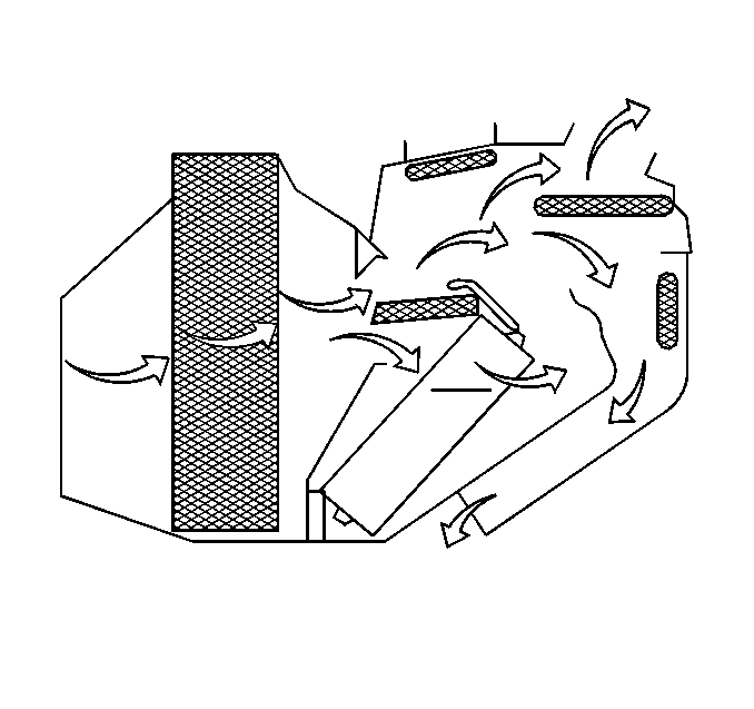
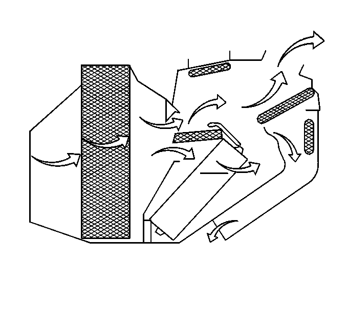
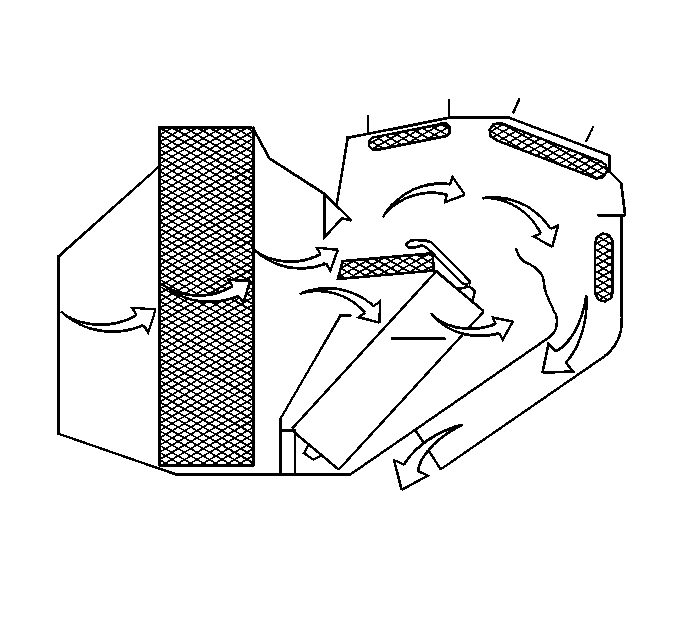
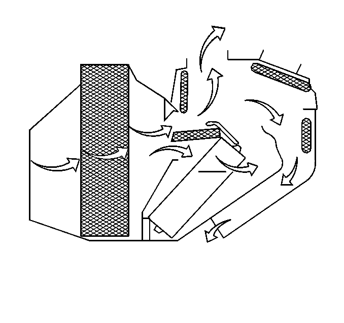
Vacuum regulates air flow through the system. Depending on the mode selected, the mode valves mix and direct either cooled, heated, or outside air through the air ducts. The various modes of operation are as follows:
- RECIRC AIR -- limits the amount of fresh air entering the vehicle by recirculating most of the air inside the vehicle. This setting helps cool the air quickly and helps to limit odors from entering the vehicle. The air is delivered through the I/P outlets.
- OUTSIDE AIR -- fresh air is drawn in from the outside and is delivered through the I/P outlets. This setting is used while defrosting or defogging the windows to help clear moisture.
- BI/LEVEL -- air is drawn from the outside and is directed into the vehicle in two ways. Cooler air is directed toward the upper body through the I/P outlets, while warmer air is directed through the lower outlets.
- UPPER -- most of the air is directed through the I/P outlets with a very small amount of the air directed to the lower outlets.
- LOWER-- most of the air is directed through the lower ducts to the floor area of the vehicle, with some of the air also being directed toward the windshield and the side window vents.
- DEFOG -- air is divided between the windshield and the lower outlets with a small amount directed toward to the side window vents. This is useful when fog appears to the windshield or side glass due to rain or snowy conditions.
- DEFROST -- most of the air is directed to the windshield for quick removal of fog or frost from the windshield. A small amount of air is also directed toward the lower and side window outlets.
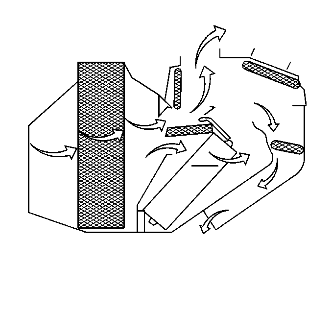
Air Intake
A vacuum actuator controls an air inlet valve. The air inlet valve position controls the air intake. The air inlet valve has two positions: up and down. When the valve is down, there is no vacuum applied to the actuator, blocking off the recirculation air opening and allowing only outside air to enter the blower. When the valve is up, there is vacuum is applied to the actuator, blocking most of the outside air and allowing about 90% of the total air supply drawn in through the blower to be recirculated through the passenger compartment.
Blower Motor
The blower motor is located in the evaporator and heater core module on the passanger side of the vehicle. A small portion of the blower output is recirculated through the blower motor housing via a rubber tube for blower motor cooling.
Temperature Door Motor
The temperature door motor is located on the left of the HVAC module on vehicles equipped with C60 systems. The temperature knob controls the motor. With the knob turned to COLD, the motor closes the temperature door, preventing air from blowing through the heater core. With the knob in any other position but COLD, the motor opens the temperature door, allowing air to pass through the heater core. The hotter the control knob setting, the more air passes through the heater core, increasing the air temperature entering the passenger compartment.
A/C Ducts
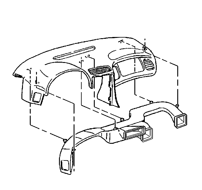
The A/C distributor is fastened to the bottom of the upper instrument pad. The distributor receives air through the HVAC module and A/C valve and channels the air to the driver, center, and passanger A/C outlets. Air is also allowed to flow to the side window defroster outlets and to the floor heater outlets.
A/C Outlets
The A/C outlets are located in the I/P and driver's door. Adjusting the air deflector control knob on the front of each outlet independently controls the air flow coming from each outlet.
Heater Outlets
There are five different heater ducts that direct air flow to the floor of the vehicle.
Driver's Front Heater Duct
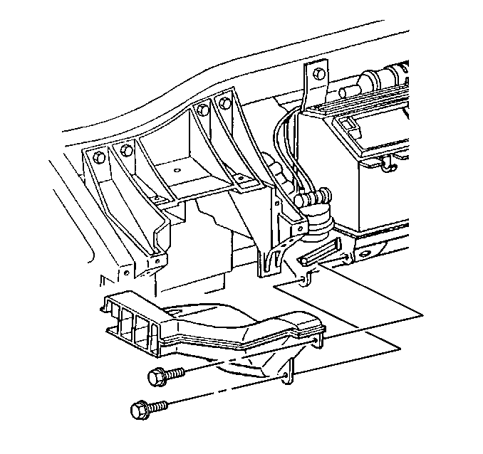
The driver's front heater duct is attached on the LH side of the hvac module and directs air flow to the front part of the driver's side floor near the driver's feet.
Driver's Rear Heater Duct
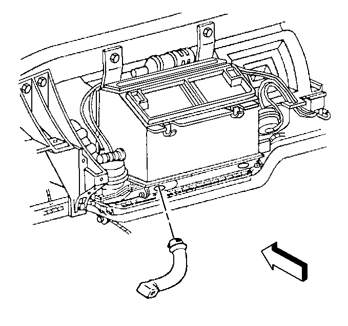
The driver's rear heater duct is attached on the LH side of the HVAC module and directs air flow to the rear part of the driver's side floor.
Passenger Front Heater Ducts
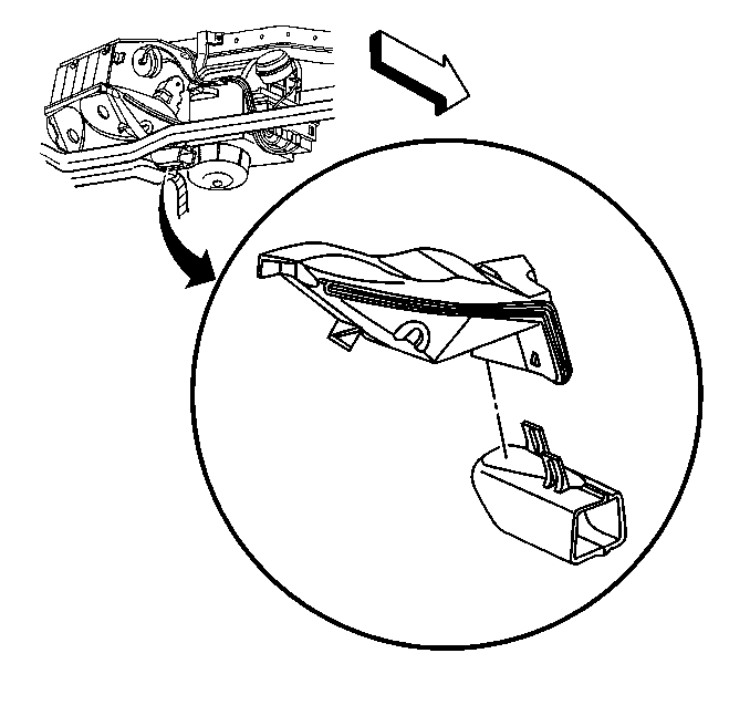
The upper passenger front heater duct is attached on the RH side of the HVAC module and the lower passenger front heater duct clips onto the upper duct. The passenger front heater ducts direct air flow to the front part of the passenger floor near the passenger's feet.
Passenger Rear Upper Heater Duct
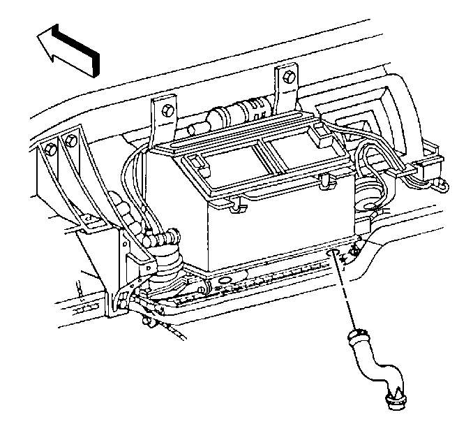
The passenger rear upper heater duct is attached to the bottom of the HVAC module and runs down the along the side of the center stack support to the passenger rear lower heater duct.
Passenger Rear Lower Heater Duct
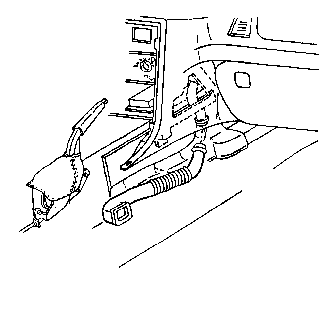
The passenger rear lower heater duct runs behind the carpet from the passenger rear upper heater duct along the drive-line tunnel toward the passenger seat. The passenger rear lower heater duct directs air flow along the drive-line tunnel to the side and behind the passenger seat.
Windshield Defroster Air Duct
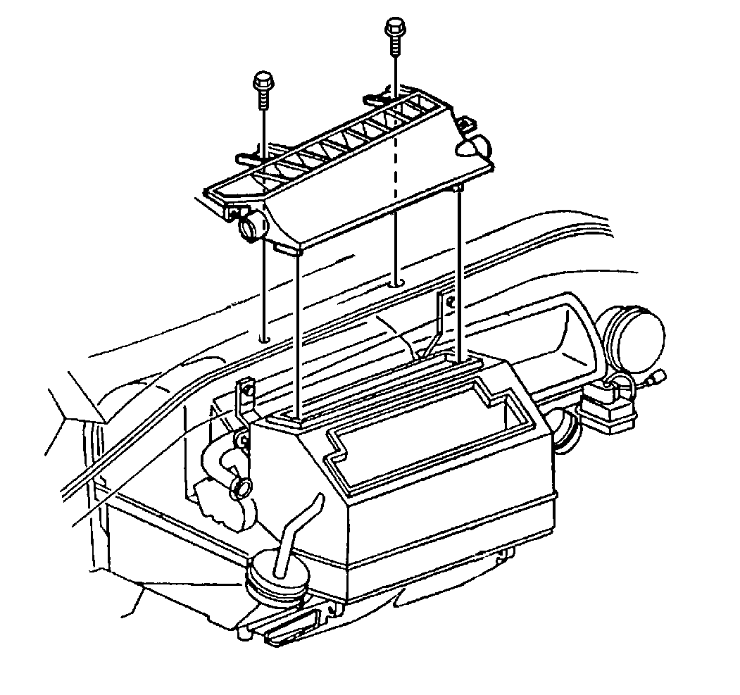
The windshield defroster air duct is located on the top of the evaporator and heater core module and directs air flow to the base of the windshield and to the side windows.
Side Window Defogger Ducts
There is a side window defogger outlet located on each side of the windshield A pillar. Air flows from the evaporator and heater core module to the RH/LH ducts and out of the ducts to the window.
