Caution: Avoid breathing the A/C Refrigerant 134a (R-134a) and the lubricant vapor or the mist. Exposure may irritate the eyes, nose, and throat. Work in a well ventilated area. In order to remove R-134a from the A/C system, use service equipment that is certified to meet the requirements of SAE J 2210 (R-134a recycling equipment). If an accidental system discharge occurs, ventilate the work area before continuing service. Additional health and safety information may be obtained from the refrigerant and lubricant manufacturers.
Notice: R-134a is the only approved refrigerant for use in this vehicle. The use of any other refrigerant may result in poor system performance or component failure.
Notice: Do not mix R-12 with R134a, even in the smallest amounts. These refrigerants are incompatible. If mixed, compressor failure is likely to occur. Use only polyalkylene glycol (PAG) synthetic refrigerant oil for internal circulation through the R-134a A/C system and only mineral base 525 viscosity refrigerant oil on the fitting threads and the O-rings. Use of a non recommended lubricant results in compressor failure and fitting seizure. Do not use compressed air in any refrigerant container or component; contamination will occur.
During A/C operation, the refrigerant circulates through the refrigerant system in order to absorb heat from the air being cooled and to send the heat to the outside. The refrigerant also carries a lubricant to parts of the compressor. Like the coolant in the engine coolant system, the refrigerant absorbs, carries, and releases the HVAC system heat. This A/C system uses R-134a, a non-toxic, non-flammable, clear gas. The following are the major components of the refrigeration system:
| • | The refrigerant |
| • | The compressor |
| • | The condenser |
| • | The expansion (orifice) tube |
| • | The evaporator core |
| • | The accumulator |
| • | The A/C lines |
| • | A refrigerant pressure sensor |
Compressor
The compressor is belt driven from the engine crankshaft through the compressor clutch pulley. The pulley rotates without driving the compressor shaft until an electromagnetic clutch coil is energized. When voltage is applied to energize the coil, the clutch plate and hub assembly are drawn rearward toward the pulley. The magnetic force locks the clutch plate and the pulley together in order to drive the compressor shaft.
Condenser
The condenser is located in front of the radiator. The condenser carries the refrigerant through the coils with cooling fins in order to provide rapid heat transfer. The air passing through the condenser cools the high pressure refrigerant vapor, causing the vapor to condense into a high pressure liquid.
Expansion (Orifice) Tube

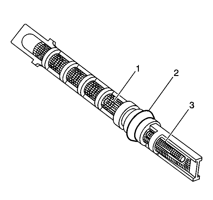
The plastic expansion (orifice) tube (2) is made of a mesh-screen (1) and orifice (3). The expansion (orifice) tube is located in the evaporator inlet pipe at the orifice connection. The tube restricts the high pressure liquid refrigerant in the liquid line, metering the refrigerant flow to the evaporator as a low pressure liquid. The expansion tube and orifice have filter screens which protect from contamination on both the inlet and outlet sides of the tube. When the engine is OFF the refrigerant in the system flows from the high pressure side of the system to the low pressure side until the pressure is equalized. This may be detected as a hissing sound for 30-60 seconds and is a normal condition.
Evaporator Core
The aluminum evaporator core cools and dehumidifies the air before the air enters the passenger compartment. High pressure liquid flows through the expansion (orifice) tube and becomes low pressure refrigerant before entering the evaporator. As the air passes through the core, the cooler surfaces absorb the heat, cooling the air. As the air is being cooled, any humidity in the air condenses on the outside of the core. The water is then drained through an opening at the bottom of the module.
Accumulator

