Removal Procedure
- Disconnect the negative battery cable from the battery. Refer to
Caution: Unless directed otherwise, the ignition and start switch must be in the OFF or LOCK position, and all electrical loads must be OFF before servicing any electrical component. Disconnect the negative battery cable to prevent an electrical spark should a tool or equipment come in contact with an exposed electrical terminal. Failure to follow these precautions may result in personal injury and/or damage to the vehicle or its components.
in General Information. - Raise and support the vehicle. Refer to Lifting and Jacking the Vehicle in General Information.
- Remove the right front wheel assembly. Refer to Wheel Removal in Tires and Wheels.
- Remove the right front wheel house filler panel. Refer to Wheelhouse Filler Replacement in Body Front End.
- Remove the PCM. Refer to Powertrain Control Module/Throttle Actuator Control Module Replacement in Engine Controls.
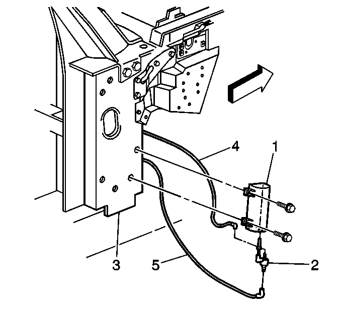
- Remove the vacuum tank (1) from the hinge pillar (3).
- Remove the vacuum tank (1) from behind the fender.
- Disconnect the vacuum line from the check valve (2).
- Disconnect the check valve (2) from the vacuum tank (1).
Installation Procedure
- Connect the check valve (2) to the vacuum tank (1).
- Connect the vacuum line to the check valve (2).
- Install the vacuum tank (1) onto the hinge pillar (3).
- Install the PCM. Refer to Powertrain Control Module/Throttle Actuator Control Module Replacement in Engine Controls.
- Install the right front wheel house filler panel. Refer to Wheelhouse Filler Replacement in Body Front End.
- Install the right front wheel assembly. Refer to Wheel Removal in Tires and Wheels.
- Lower the vehicle.
- Connect the negative battery cable. Refer to
Caution: Unless directed otherwise, the ignition and start switch must be in the OFF or LOCK position, and all electrical loads must be OFF before servicing any electrical component. Disconnect the negative battery cable to prevent an electrical spark should a tool or equipment come in contact with an exposed electrical terminal. Failure to follow these precautions may result in personal injury and/or damage to the vehicle or its components.
in General Information.
| 3.1. | Install the upper screw first, then install the lower screw. |
| 3.2. | Tighten the upper screw first, then tighten the lower screw. |
Tighten
Tighten the vacuum tank screws to 3.5 N·m (31 lb in).
Notice: Use the correct fastener in the correct location. Replacement fasteners must be the correct part number for that application. Fasteners requiring replacement or fasteners requiring the use of thread locking compound or sealant are identified in the service procedure. Do not use paints, lubricants, or corrosion inhibitors on fasteners or fastener joint surfaces unless specified. These coatings affect fastener torque and joint clamping force and may damage the fastener. Use the correct tightening sequence and specifications when installing fasteners in order to avoid damage to parts and systems.
