Brake Caliper Replacement Front
Removal Procedure
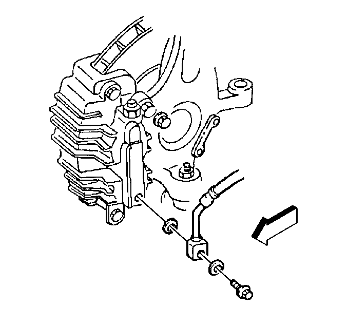
- Raise the vehicle and support. Refer to
Lifting and Jacking the Vehicle
in General Information.
- Remove the tire and wheel assembly.
- Remove the inlet fitting bolt, inlet fitting, and two gaskets
only if the brake caliper housing is being removed from the vehicle.
| 3.1. | Discard the two gaskets. |
| 3.2. | Plug the openings in the brake caliper housing and the inlet fitting. |
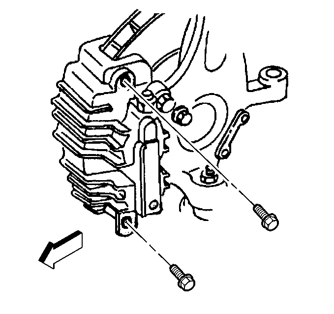
- Remove the brake caliper guide pin bolts.
- Remove the brake caliper housing from the brake rotor and the
brake caliper mounting bracket.
- If a brake caliper housing overhaul or replacement is not required,
support the brake caliper housing using a wire hook or equivalent to avoid
damage to the brake hose.
- Remove the brake pads only if they are being replaced or if the
brake caliper mounting bracket is being removed.
Installation Procedure

- Install the brake pads, if removed.
| 1.1. | Install the outboard brake pad with the insulator installed toward
the brake caliper housing. |
| 1.2. | Install the inboard brake pad with the wear sensor installed nearest
the brake caliper piston. |
| 1.3. | The wear sensor must be in the trailing position during forward
wheel rotation. |
- Install the brake caliper housing over the brake rotor and into
the brake caliper mounting bracket.
- Install the brake caliper guide pin bolts.
Tighten
Tighten the brake caliper guide pin bolts to 31 N·m (23 lb ft).
Notice: Use the correct fastener in the correct location. Replacement fasteners
must be the correct part number for that application. Fasteners requiring
replacement or fasteners requiring the use of thread locking compound or sealant
are identified in the service procedure. Do not use paints, lubricants, or
corrosion inhibitors on fasteners or fastener joint surfaces unless specified.
These coatings affect fastener torque and joint clamping force and may damage
the fastener. Use the correct tightening sequence and specifications when
installing fasteners in order to avoid damage to parts and systems.

- Install the inlet fitting, two new gaskets and the inlet fitting bolt, if
removed.
Tighten
Tighten the brake caliper inlet fitting bolt to 40 N·m
(30 lb ft).
- Bleed the hydraulic brake system, If the inlet fitting was removed.
Refer to
Hydraulic Brake System Bleeding
in Hydraulic Brakes.
- Install the tire and wheel assembly.
Tighten
Tighten the wheel nuts in sequence to 140 N·m (100 lb ft).
- Lower the vehicle.
- Refill the master cylinder reservoir. Refer to
Master Cylinder Description
in Hydraulic Brakes.
- With the engine running, pump the brake pedal slowly and firmly
three times to seat the brake pads.
- Inspect the hydraulic brake system for brake fluid leaks.
Brake Caliper Replacement Rear
Removal Procedure
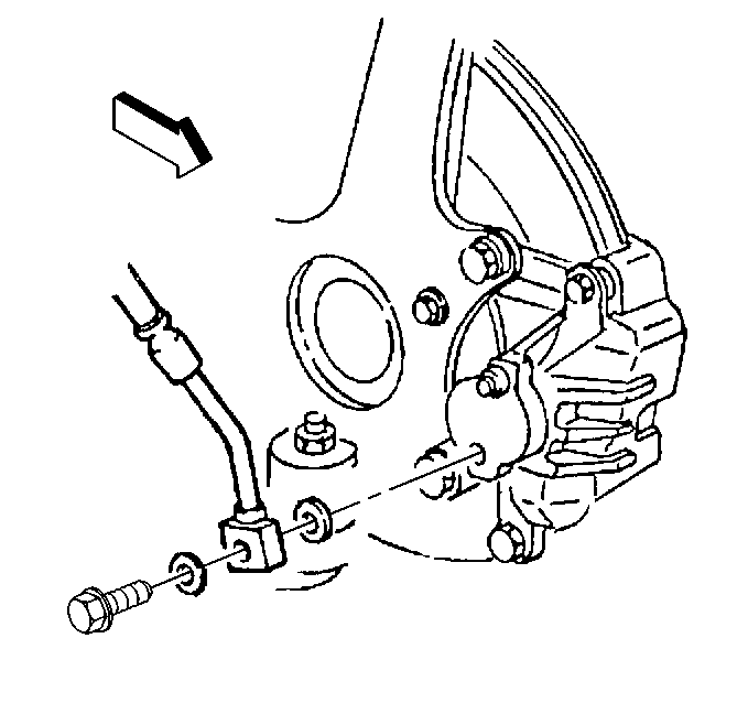
- Raise the vehicle and support. Refer to
Lifting and Jacking the Vehicle
in General information.
- Remove the tire and wheel assembly.
- Remove the inlet fitting bolt, inlet fitting, and two gaskets
only if the brake caliper housing is being removed from the vehicle.
| 3.1. | Discard the two gaskets. |
| 3.2. | Plug the openings in the brake caliper housing and the inlet fitting. |
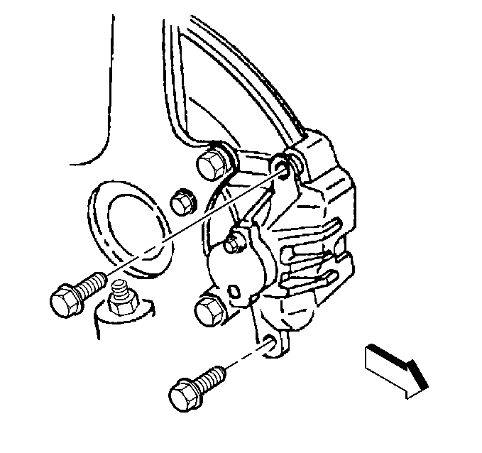
- Remove the brake caliper guide pin bolts.
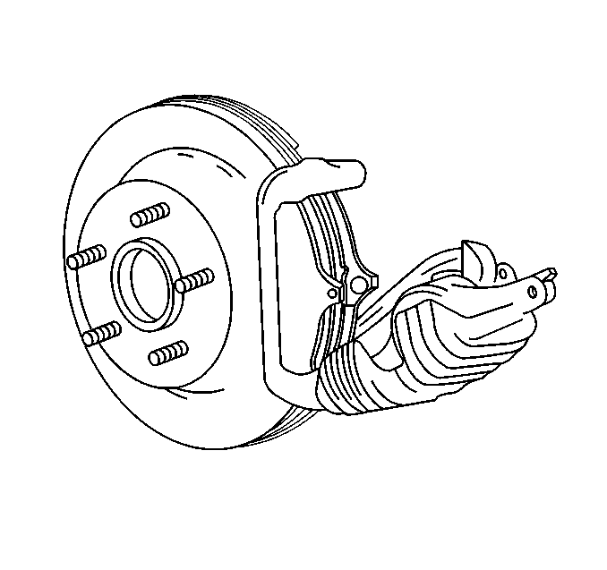
- Remove the brake caliper housing from
the brake rotor and the brake caliper mounting bracket.
- If a brake caliper housing overhaul or replacement is not required,
support the brake caliper housing using a wire hook or equivalent to avoid
damage to the brake hose.
- Remove the brake pads only if they are being replaced or if the
brake caliper mounting bracket is being removed.
Installation Procedure

- Install the brake pads, if removed.
| 1.1. | Install the outboard brake pad with the insulator installed toward
the brake caliper housing. |
| 1.2. | Install the inboard brake pad with the wear sensor installed nearest
the brake caliper piston. |
| 1.3. | The wear sensor must be in the trailing position during forward
wheel rotation. |
- Install the brake caliper housing over the brake rotor and into
the brake caliper mounting bracket.

- Install the brake caliper guide pin bolts.
Tighten
Tighten the brake caliper guide pin bolts to 31 N·m (23 lb ft).
Notice: Use the correct fastener in the correct location. Replacement fasteners
must be the correct part number for that application. Fasteners requiring
replacement or fasteners requiring the use of thread locking compound or sealant
are identified in the service procedure. Do not use paints, lubricants, or
corrosion inhibitors on fasteners or fastener joint surfaces unless specified.
These coatings affect fastener torque and joint clamping force and may damage
the fastener. Use the correct tightening sequence and specifications when
installing fasteners in order to avoid damage to parts and systems.

- Install the inlet fitting, two new gaskets and the inlet fitting bolt, if
removed.
Tighten
Tighten the brake caliper inlet fitting bolt to 40 N·m
(30 lb ft).
- Bleed the hydraulic brake system, If the inlet fitting was removed.
Refer to
Hydraulic Brake System Bleeding
in Hydraulic Brakes.
- Install the tire and wheel assembly.
Tighten
Tighten the wheel nuts in sequence to 140 N·m (100 lb ft).
- Lower the vehicle.
- Refill the master cylinder reservoir. Refer to
Master Cylinder Description
in Hydraulic Brakes.
- With the engine running, pump the brake pedal slowly and firmly
three times to seat the brake pads.
- Inspect the hydraulic brake system for brake fluid leaks.


