SMU - Revised Rear Axle-Assemble Procedure and Special Tools

| Subject: | Revised Rear Axle-Assemble Procedure and Special Tools |
| Models: | 1997-2003 Chevrolet Corvette |
This bulletin is being issued to revise the Rear Axle-Assemble procedure and Special Tools in the Rear Drive Axle sub-section of the Service Manual. Please replace the current information in the Service Manual with the following information.
The following information has been updated within SI. If you are using a paper version of this Service Manual, please make a reference to this bulletin on the affected page.
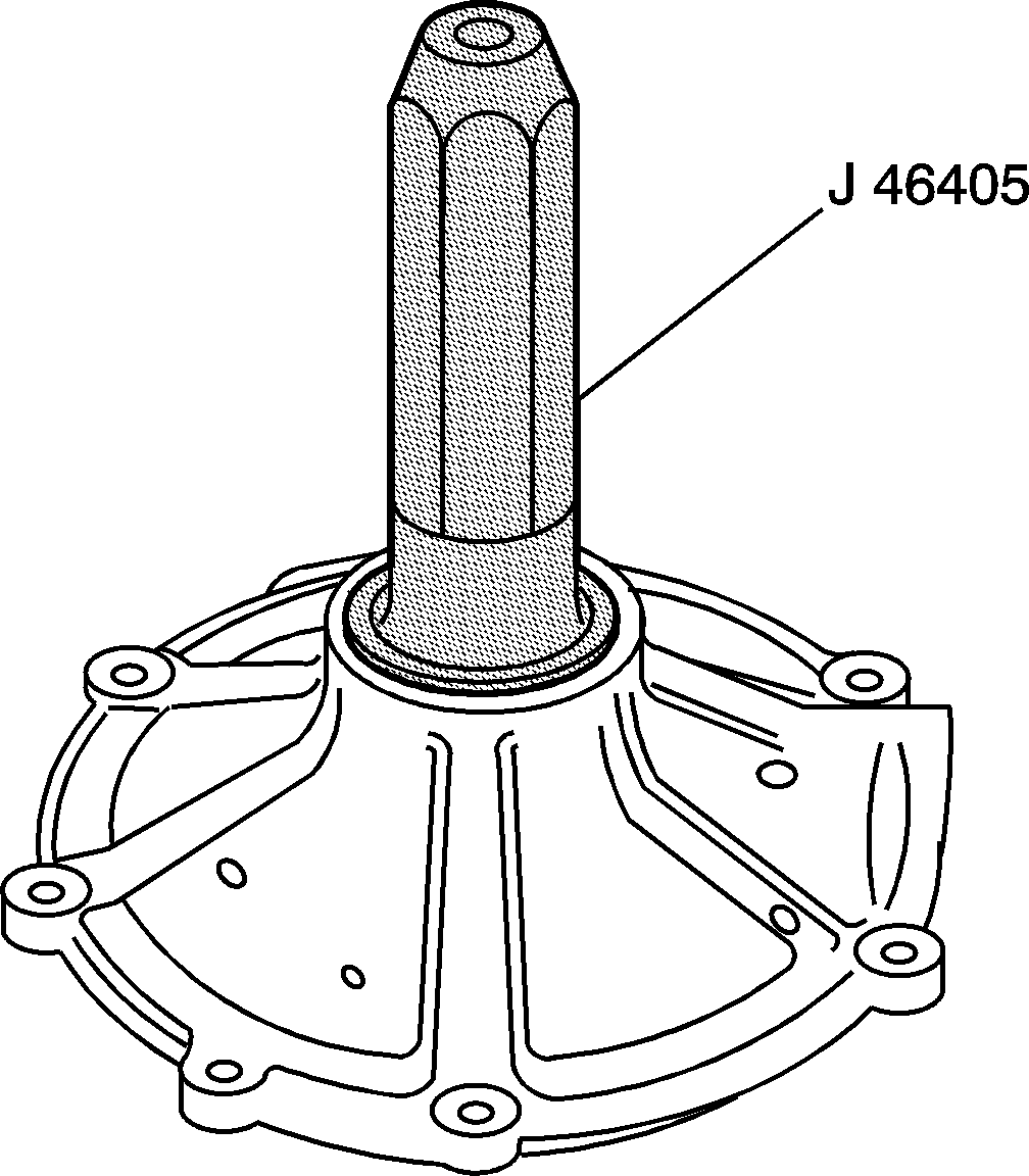
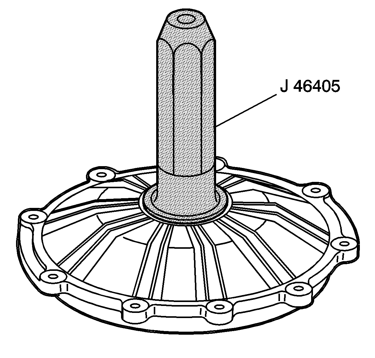
The Rear Axle-Assemble procedure below has been revised because a new special tool has been developed. Tool J 46405, Output Shaft Seal Installer, will replace J 36797. The Special Tools section has also been revised to show this new tool.
A new seal installer was required due to an axle shaft oil seal design change. This new tool will work with either the new or old design seal.
The old design seal (P/N 12369460) will be used until stock is depleted. At that point, the new seal (P/N 88996703) will supersede the old part.
Rear Axle - Assemble
Tool Required
| • | J 8001 Dial Indicator Set |
| • | J 46405 Output Shaft Seal Installer |
| • | J 42155 Differential Lifting Tool |
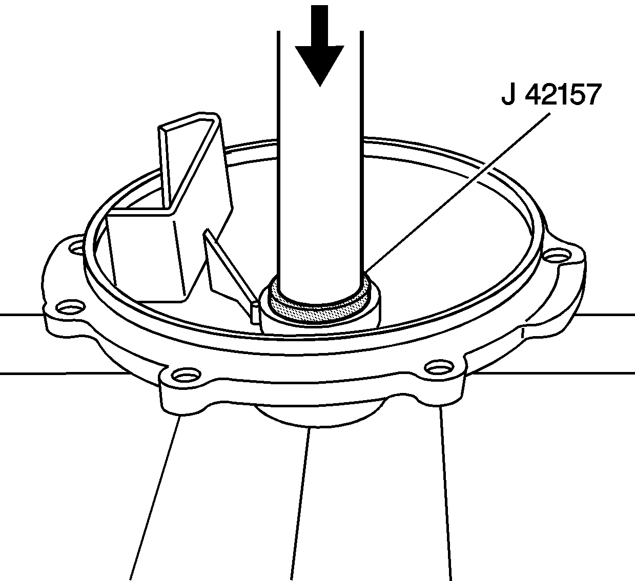
| • | J 42157 Left Output Shaft Bearing Installer |
| • | J 42164 Pinion Gear Holder |
| • | J 42170 Bearing and Race Installer |
| • | J 42173 Differential Holding Fixture |
- Assemble the drive pinion prior to rear axle assembly. Refer to Drive Pinion Assemble.
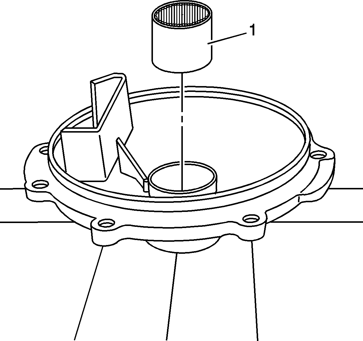
- Install the bearing (1) to the cover - left.
- Install the bearing into the cover - left using the J 42157 and a hydraulic press.
- Install the oil seal into the cover - left using the J 46405 .
- Install the oil seal into the cover - right using the J 46405.
- Install the pinion housing assembly (2) and the selected shim or shims (1) to the differential housing. Refer to Drive Pinion Shim Selection for shim selection.
- Install the pinion housing/cage bolts (1).
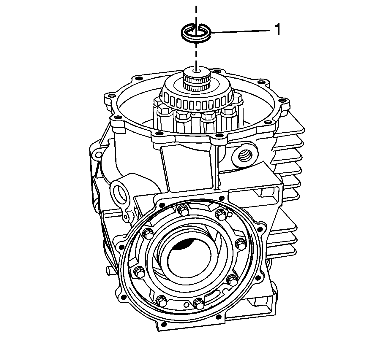
- Install the C-clip (1) into the groove of the output shaft.
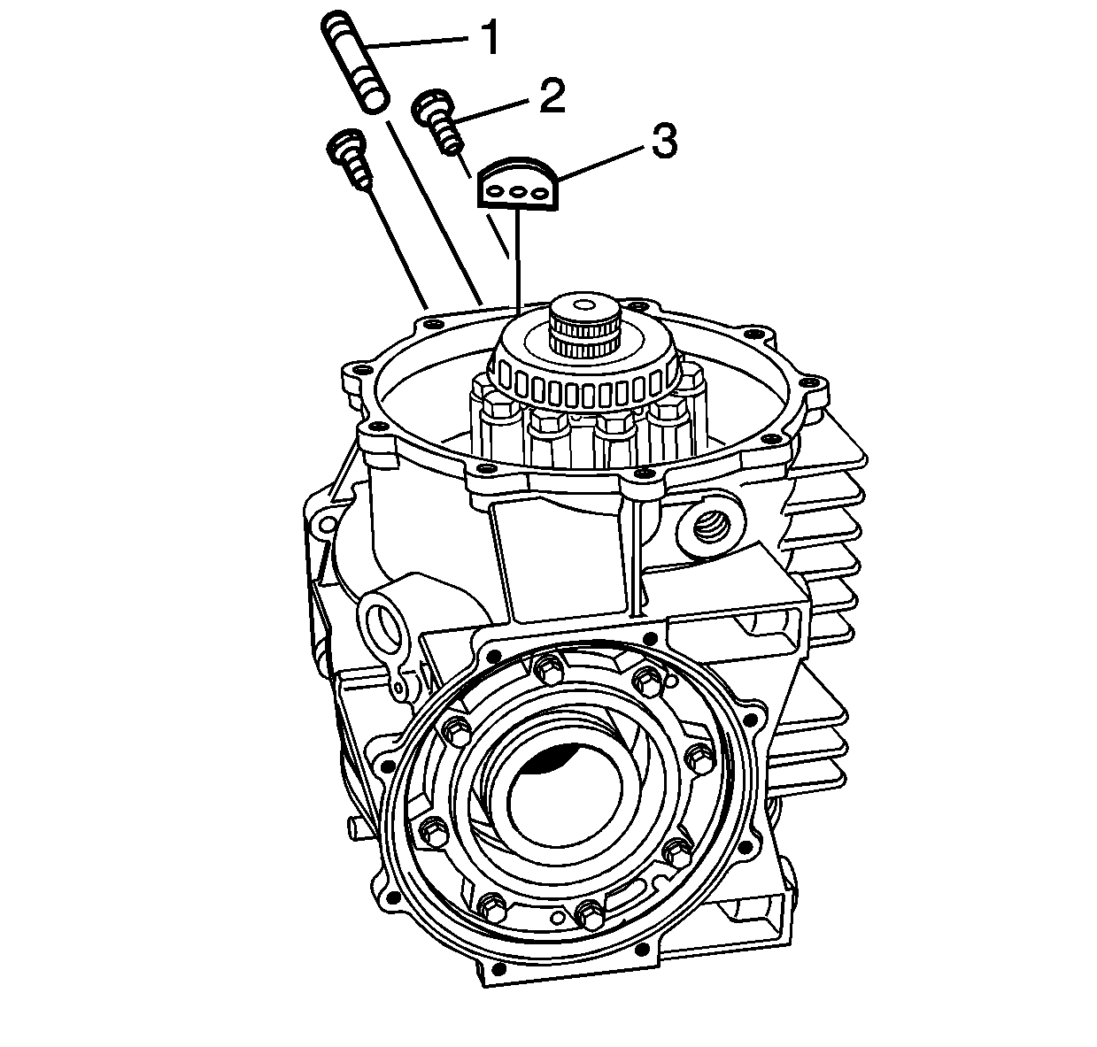
- Apply threadlocker GM P/N 1052942 (Canadian P/N 10953466) or equivalent to the threads of the bolts (2) and stud (1). Apply threadlocker only to the end of the stud that installs into the mount.
- Install the mount (3) and bolts (2).
- Install 2 M10 x 1.5 nuts onto the transmission stud (1). Install the stud into the mount.
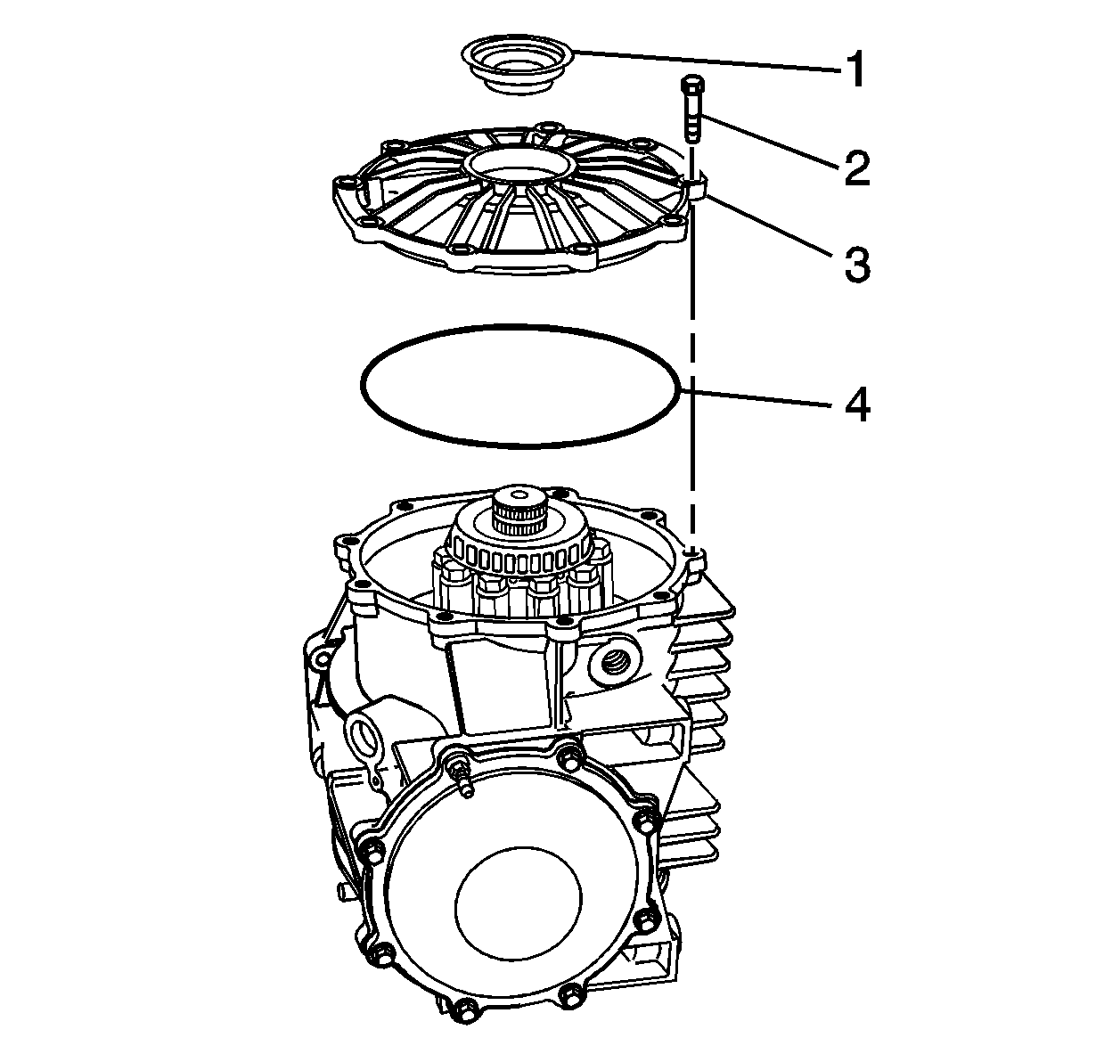
- Install the O-ring (4) to the groove of the cover - right (3).
- Install the cover - right and bolts (2).
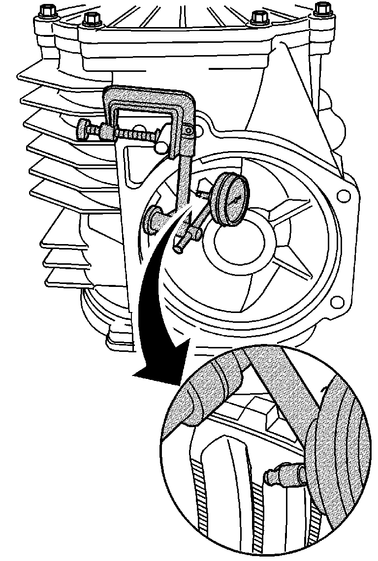
- Install the J 8001 onto the transmission stud. Position the tip of the dial indicator against the center of the ring gear tooth surface.
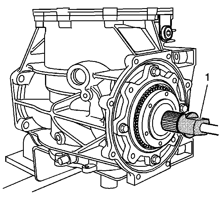
- Install the J 42164 (1) into the splines of the pinion. J 42164 will retain the pinion in order to properly measure backlash.
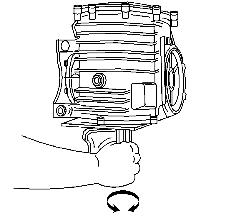
- Move the output shaft - right in both directions in order to measure the gear backlash. Measure the backlash in two to three locations. Refer to Rear Axle Specifications.
- Install the cover - rear (2), bolts (3), bolt/stud (4), and O-ring (1).
- Remove the bolts (3) and the differential assembly (1) from the J 42173 (2).
- Install the O-ring (4) into the groove of the cover - left (3).
- Install the magnet (5) to the carrier.
- Install the cover - left (3) and bolts (2).
- Install the vehicle speed sensor and bolt.
- Install the drain plug (1) and washer (2).
- Install the fill plug (3), lubricant tag (2), and washer (1).
- Install the transmission mount and bolts.
Important: If the pinion assembly components have not been replaced, reuse the original pinion housing shims. If the pinion assembly components have been replaced, refer to Drive Pinion Shim Selection for selection of the proper size shims.
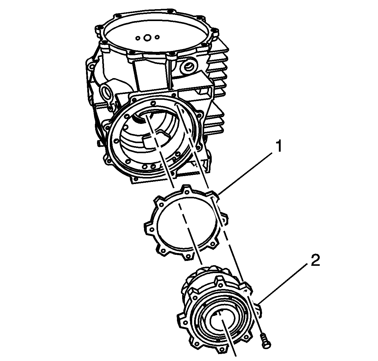
The use of M8 x 1.25 dowels or long bolts will ease in pinion housing/cage and shim installation and alignment.
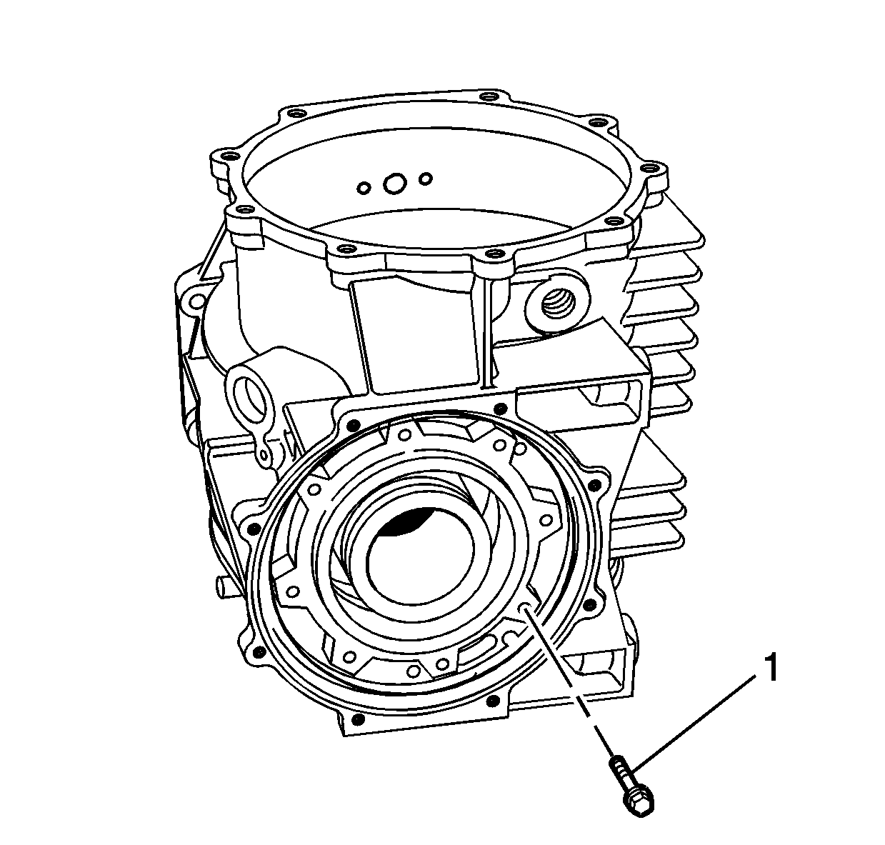
Notice: Refer to Fastener Notice in Cautions and Notices.
Tighten
Tighten the bolts to 25 N·m (18 lb ft).
Tighten
Tighten the bolts to 10 N·m (89 lb in).
Tighten
Tighten the stud to 42 N·m (31 lb ft).
Tighten
Tighten the bolts to 25 N·m (18 lb ft).
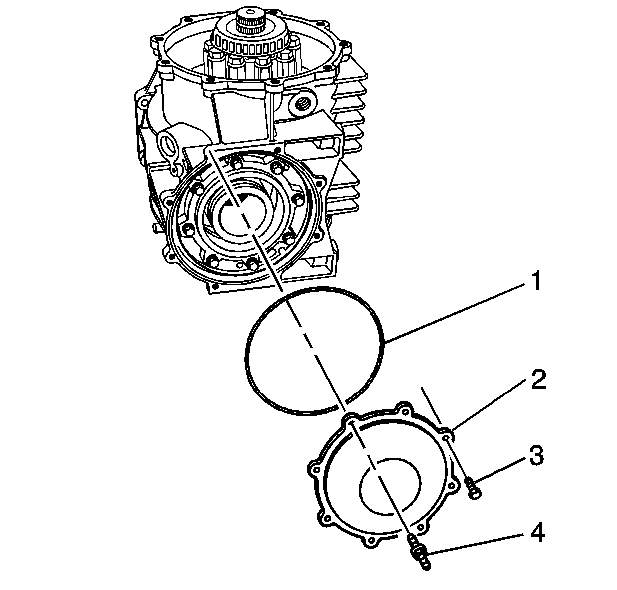
Important: Note the location of the cover - rear bolt/stud for assembly.
Tighten
Tighten the bolts and bolt/stud to 10 N·m (89 lb in).
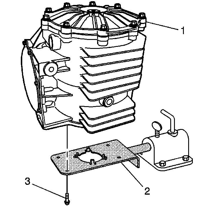
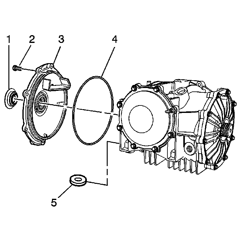
Tighten
Tighten the bolts to 25 N·m (18 lb ft).
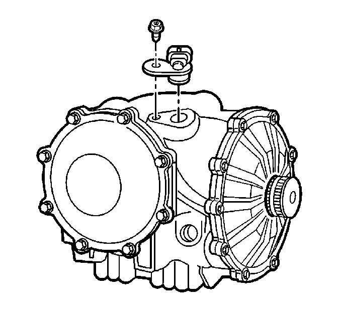
Tighten
Tighten the bolt to 25 N·m (18 lb ft).
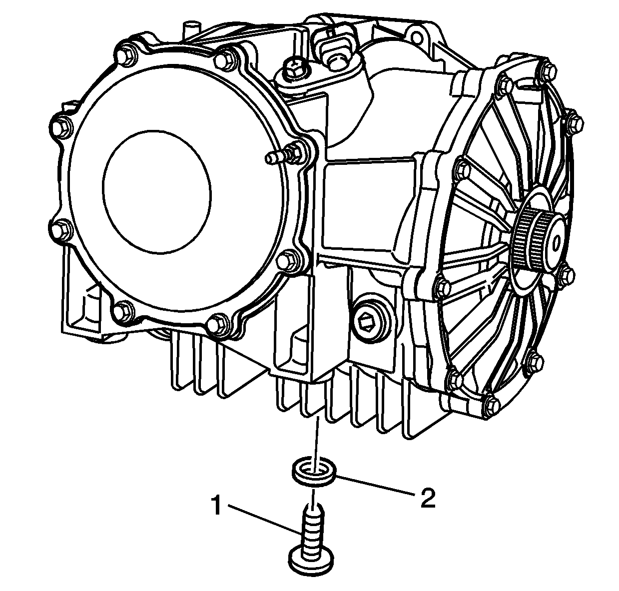
Tighten
Tighten the drain plug to 35 N·m (26 lb ft).
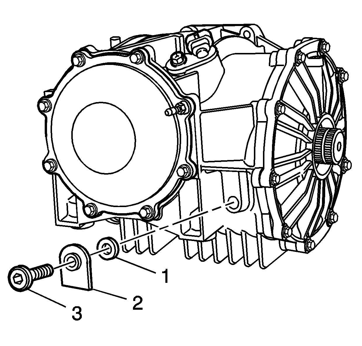
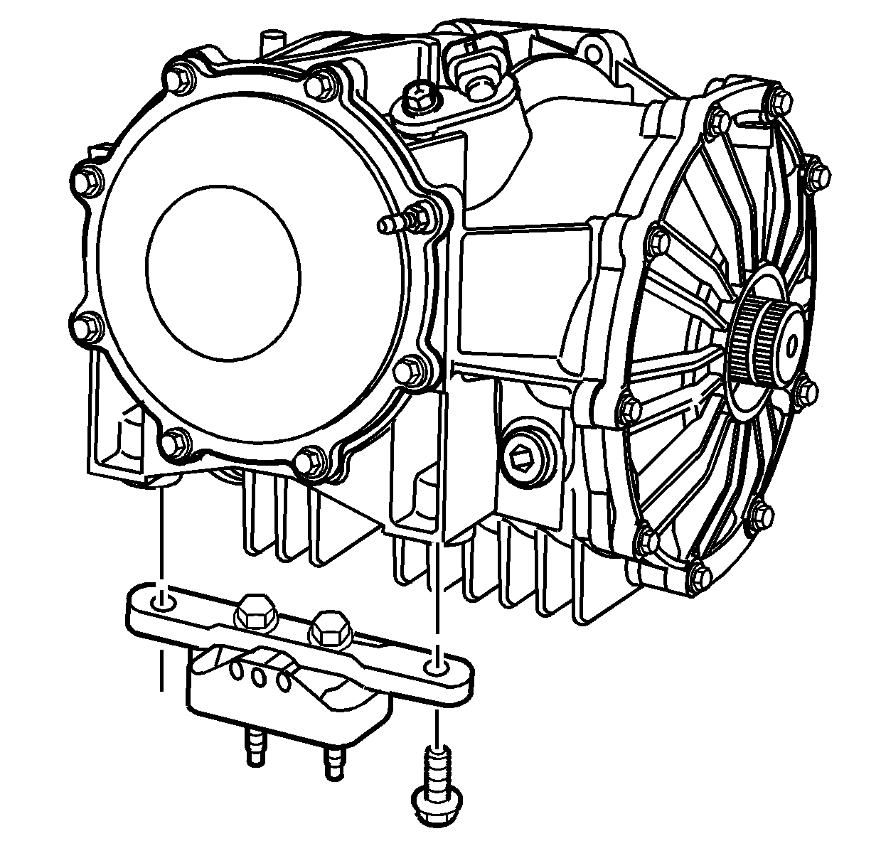
Tighten
Tighten the bolts to 50 N·m (37 lb ft).
