SMU - Getrag Rear Drive Axle - Revised Set-up and Measurement Procedures/J 42168

| Subject: | Getrag Rear Drive Axle -- Revised Set-up and Measurement Procedures Using Tool J 42168 |
| Models: | 1997-2001 Chevrolet Corvette |
This bulletin is being issued to revise the Drive Pinion Shim Selection and Differential Side Bearings Assemble procedures. In addition, example shim calculation tables have been added within Spacer and Shim Specifications in the Rear Drive Axle section of the Service Manual. The revisions incorporate the use of J 42168 and the correct calculation procedures for proper shim(s) selection. Service Information 2000, available through the GM Access server or web information (version 08.08) or CD ROM (version 09.00) or later, will contain the updated information.
Drive Pinion Shim Selection
Tools Required
| • | J 42168-1 Differential Centerline Cylinder |
| • | J 42168-2 Shim Gauge Assembly |
| • | J 42168-9 Centerline Cylinder Holding Strap |
| • | J 42168-11 Pinion Housing Centering Spacer |
| • | J 42173 Differential Holding Fixture |
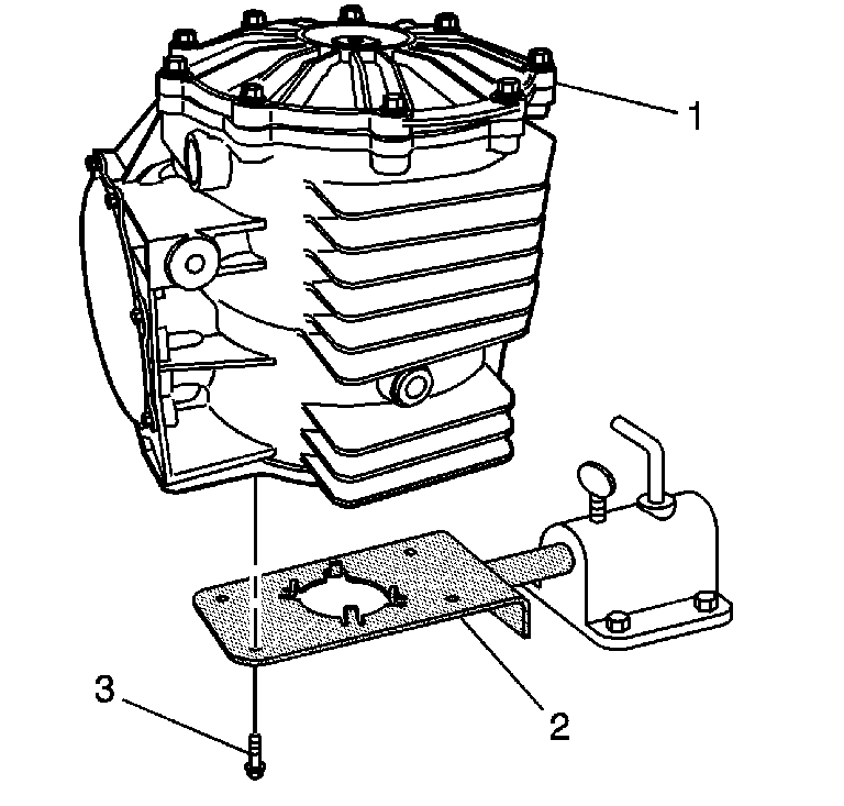
- Install the differential assembly (1) onto the J 42173 (2).
- Install four M8 x 1.25 bolts (3).
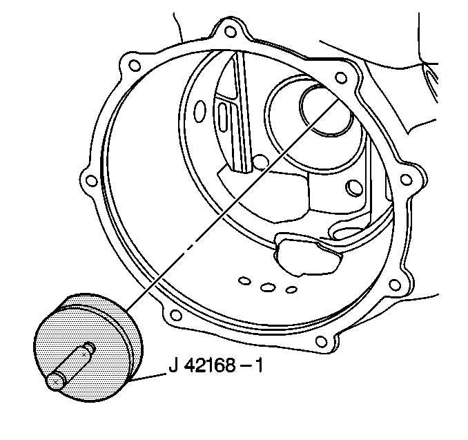
- Install the J 42168-1 into the left bearing race bore of the differential housing.
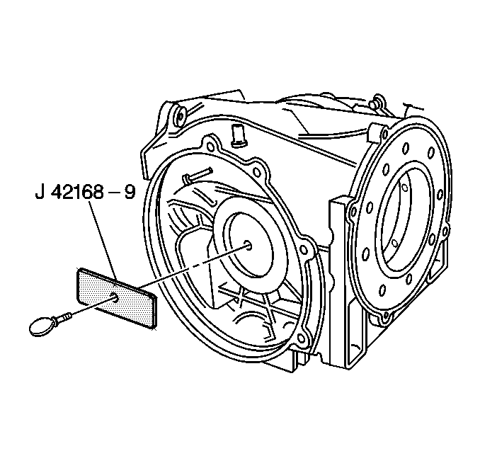
- Install the J 42168-9 and thumbscrew to the J 42168-1. Tighten the thumbscrew until snug.
- Install the bearing races into the pinion housing (4). Refer to Drive Pinion Assemble.
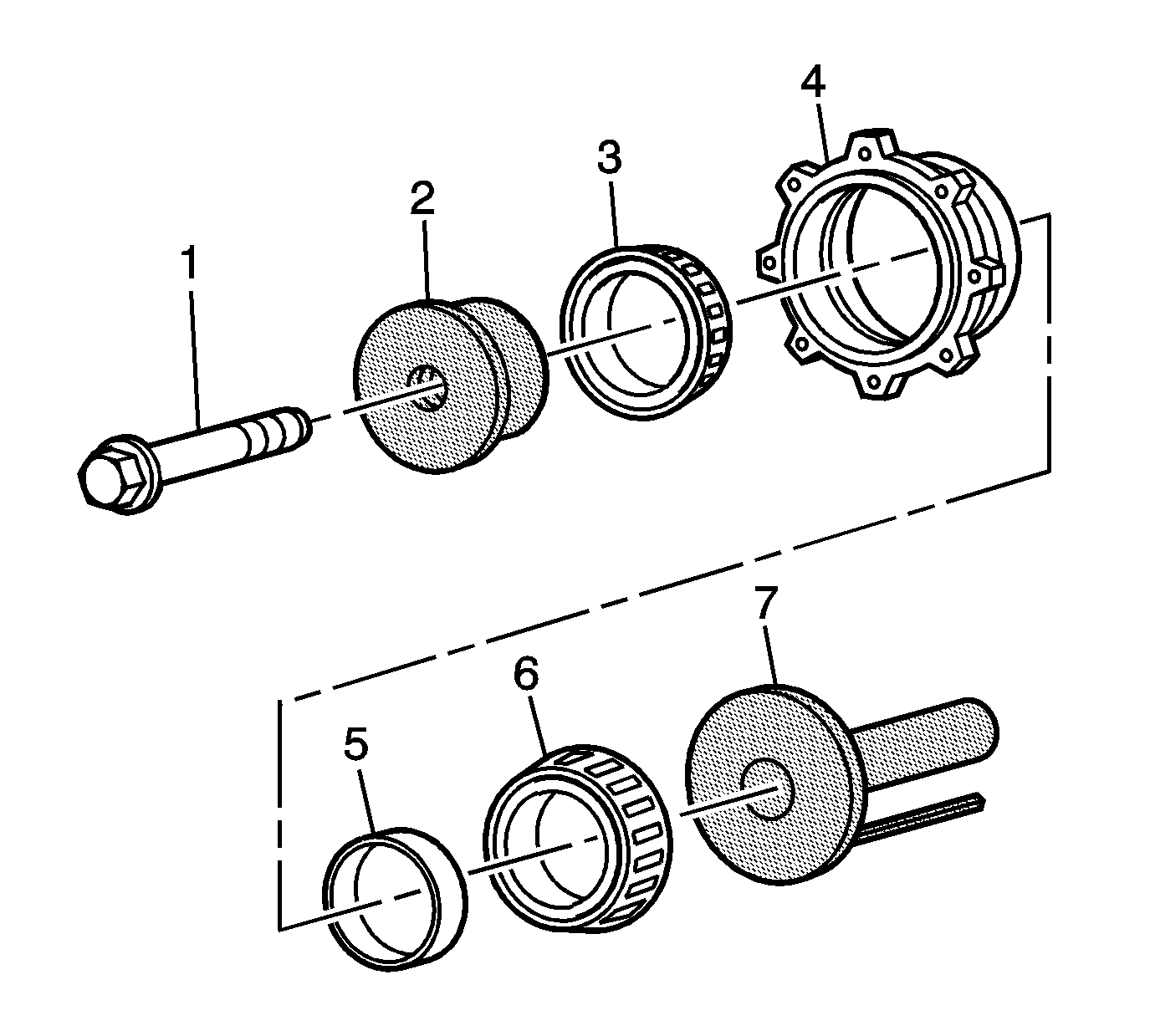
- Install the J 42168-11 (2), bearings (3 and 6), spacer (5), J 42168-2 (7), and bolt (1) to the pinion housing (4). Tighten the bolt until snug.
- Install the pinion housing assembly (1) into the differential housing.
- Install the pinion housing bolts (1).
- Using a feeler gauge, measure the distance between the J 42168-2 and the J 42168-1. Record the dimension as B1.
- Subtract the B1 value from a B nominal value of 5 mm (0.197 in). Record that calculation as B2.
- Locate the A1 value (1) on the side of the ring gear.
- Subtract the A nominal value of 103.00 mm (4.055 in) from the A1 value. Record the calculation as B3.
- Add the B2 value to the B3 value for the proper pinion housing shim thickness. The B3 value may be a positive, negative, or zero value.
- Select shims equal to the calculated value. It may be necessary to round the shim(s) total to obtain the proper size shim pack. If the shim thickness calculation is past the midpoint value, round the number higher to the next decimal value.
Important: The pinion depth adjustment procedure and shim selection must be performed prior to pinion shaft and housing assembly.
Notice: Use the correct fastener in the correct location. Replacement fasteners must be the correct part number for that application. Fasteners requiring replacement or fasteners requiring the use of thread locking compound or sealant are identified in the service procedure. Do not use paints, lubricants, or corrosion inhibitors on fasteners or fastener joint surfaces unless specified. These coatings affect fastener torque and joint clamping force and may damage the fastener. Use the correct tightening sequence and specifications when installing fasteners in order to avoid damage to parts and systems.
Tighten
Tighten the bolts to 25 N·m (18 lb ft).
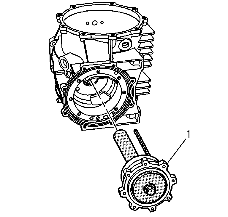
The use of M8 x 1.25 dowels or long bolts will ease in pinion housing installation and alignment.
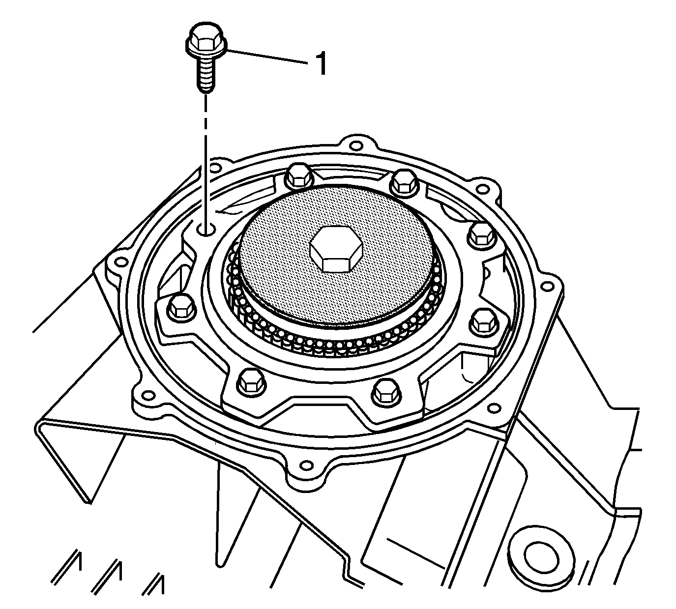
Important: ALL of the pinion housing bolts must be installed in order to obtain an accurate measurement and correct shim selection.
Tighten
Tighten the bolts to 25 N·m (18 lb ft).
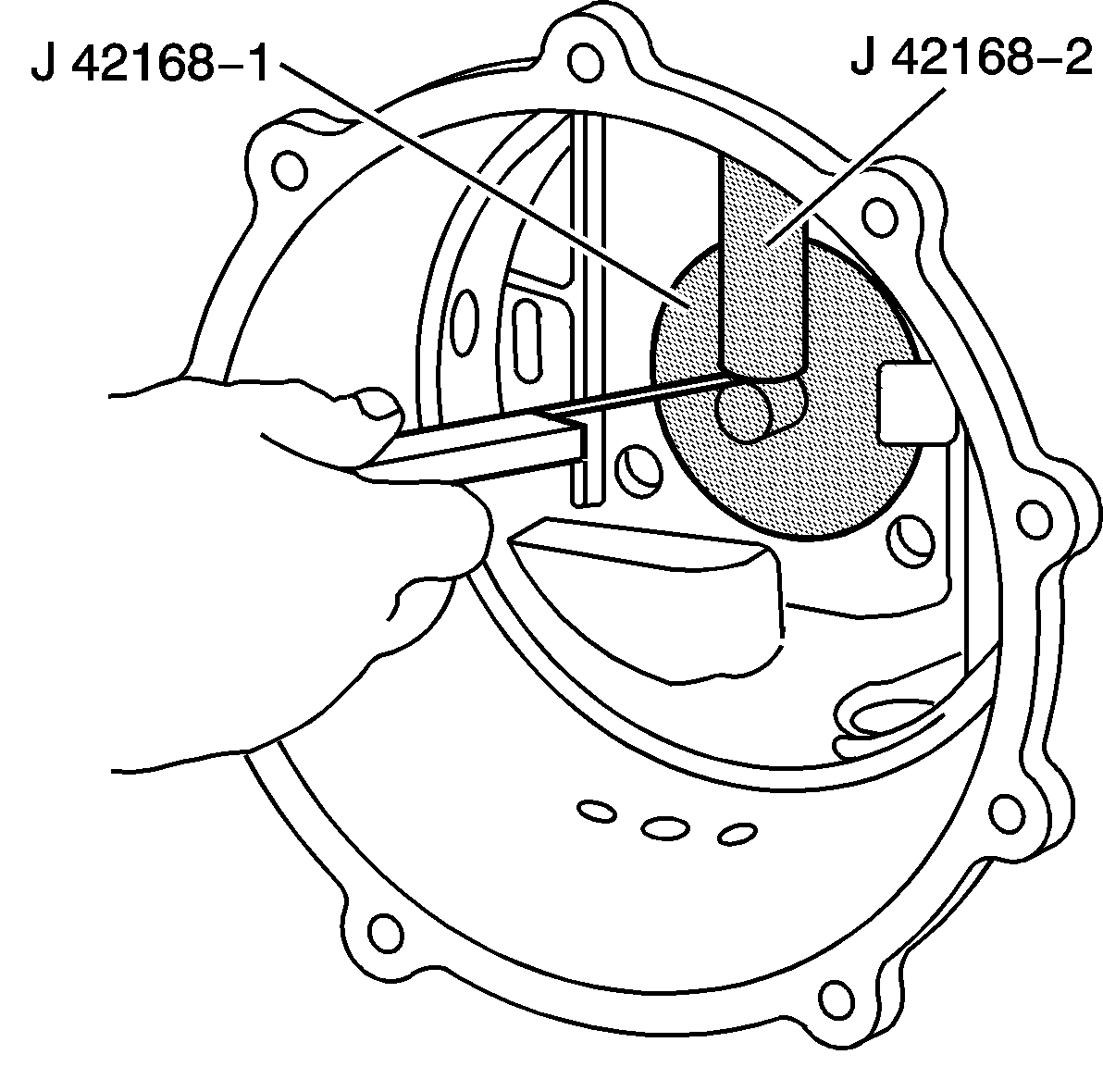
Refer to the applicable calculation tables in Spacer and Shim Specifications.
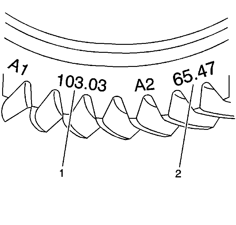
Important: The A1 value is a manufacturing variation between the ring gear and pinion. The A1 value may be higher, lower, or equal to 103.00 mm (4.055 in) nominal value. When subtracting the A nominal value from the A1 value, the B3 calculation may compute to a positive, negative, or zero total.
Refer to Rear Axle Specifications.
Differential Side Bearings Assemble
Tools Required
| • | J 42155 Differential Lifting Tool |
| • | J 42168-1 Differential Centerline Cylinder |
| • | J 42168-2 Shim Gauge Assembly |
| • | J 42168-7 Depth Gauge |
| • | J 42168-9 Centerline Cylinder Holding Strap |
| • | J 42168-11 Pinion Housing Centering Spacer |
| • | J 42168-13 Gauge Plate Assembly |
| • | J 42168-15 Side Bearing Shim Selector |
| • | J 42168-16 Right Side Cover Spacers |
| • | J 42170 Bearing and Race Installer |
| • | J 42173 Differential Holding Fixture |
- Remove the J 42168-9 and thumbscrew from the J 42168-1.
- Remove the J 42168-1 from the left bearing race bore of the differential housing.
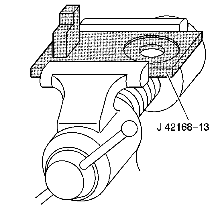
- Install the J 42168-13 into a vice.
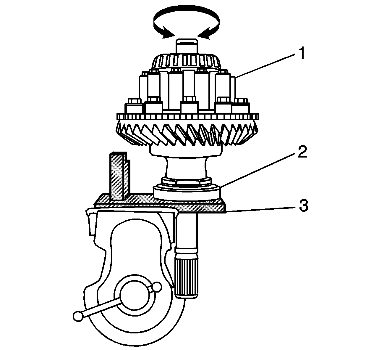
- Position the bearing race (2) onto the J 42168-13 (3).
- Use the J 42173 in order to position the differential case (1) onto the J 42168-13 (3) and into the bearing race (2). Rotate the differential (in both directions) in order to seat the bearing to the race.
- Install the J 42168-7 into the hole in J 42168-2 (1). Loosen the thumbscrew and allow the rod to contact the bottom of the bearing race bore (machined surface) (3).
- Tighten the thumbscrew.
- Remove the J 42168-7 from the J 42168-2.
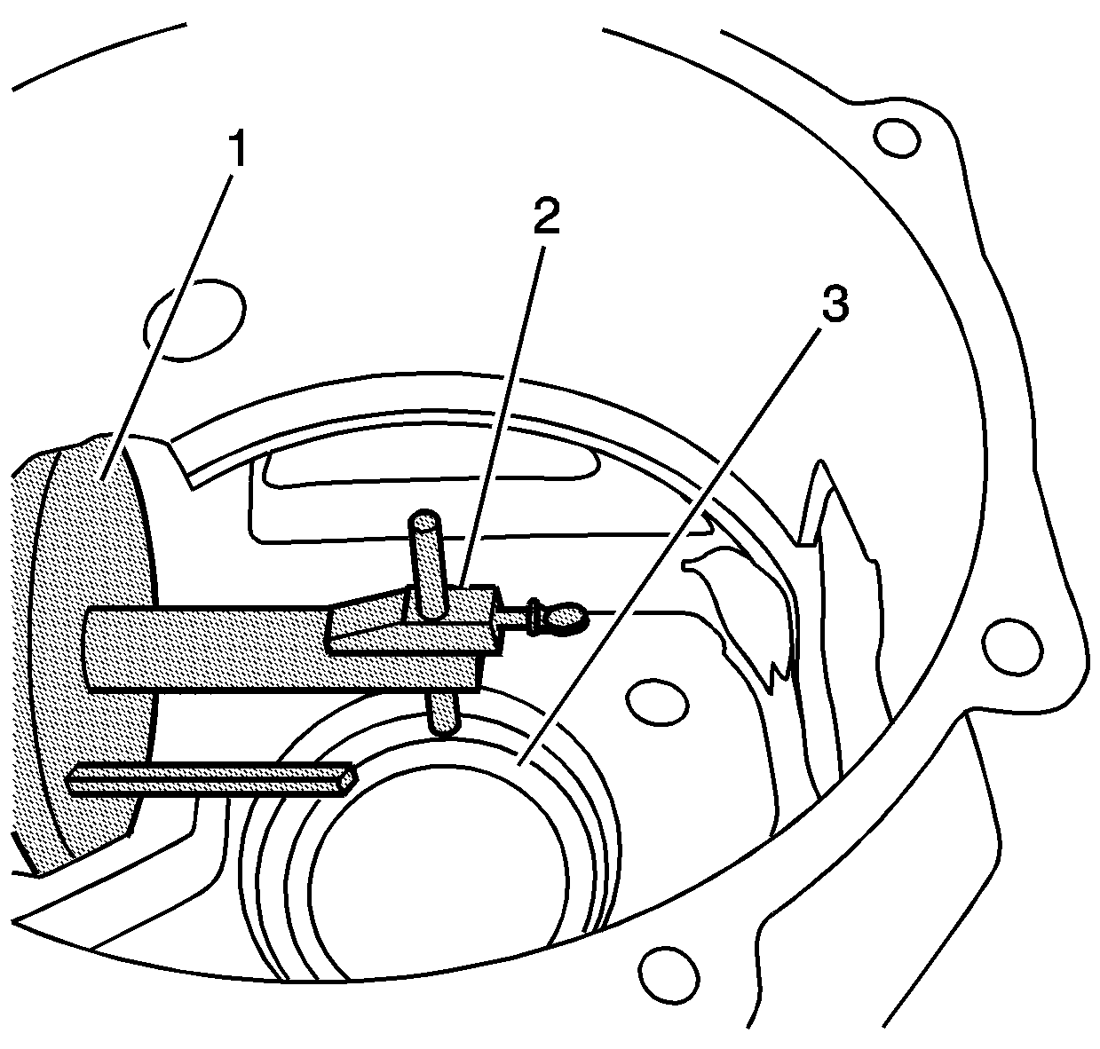
- Install the J 42168-7 (2) into one of the two oil passages of the differential (1). The tapered portion of the tool will wedge and be retained into the differential.
- Rotate the differential until the rod of J 42168-7 is above the J 42168-13 (3) gauge block.
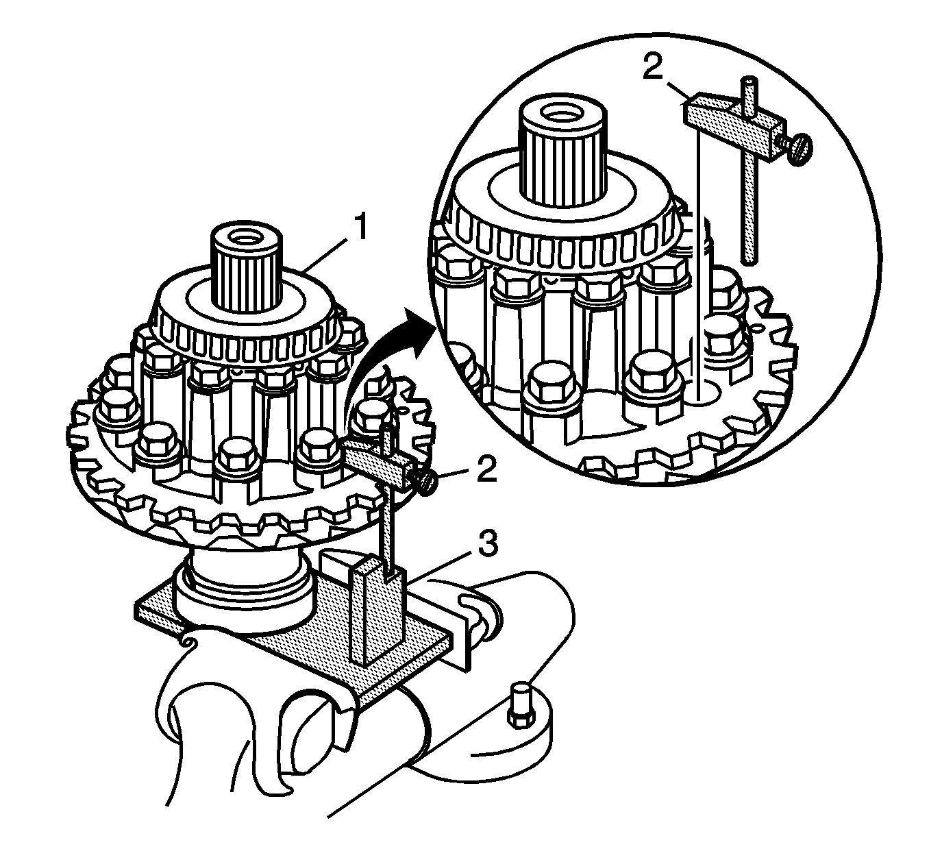
- The J 42168-13 upper gauge block location (1) is used when servicing 2.73 ratio differentials. The lower gauge block location (2) is used when servicing the 3.15 and 3.42 ratio differentials.
- Using a feeler gauge, measure the distance between the rod of J 42168-7 and the gauge block of J 42168-13. Record the measurement as dimension C1.
- Subtract C1 value from a C nominal value of 5 mm (0.197 in). Record that calculation as C2.
- Locate the A2 value (2) on the side of the ring gear.
- Subtract the D nominal value of either 65.5 mm (2.58 in) or 74.5 mm (2.93 in) from the A2 value. Record the calculation as C3.
- Add the C2 value to the C3 value for the proper left side differential bearing shim thickness. The C3 value may be a positive, negative, or zero value.
- Select shims equal to the calculated value. It may be necessary to round the shim(s) total to obtain the proper shim sizes. If the shim thickness calculation is past the midpoint value, round the number to the next decimal value. Refer to Rear Axle Specifications.
- Remove the pinion housing bolts (1).
- Remove the pinion housing (1) from the differential.
- Remove the J 42168-11, bearings (3 and 6), spacer (5), and J 42168-2 (7) from the pinion housing (4).
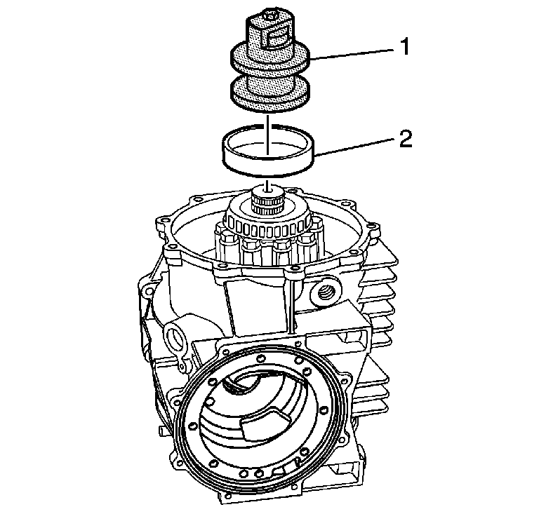
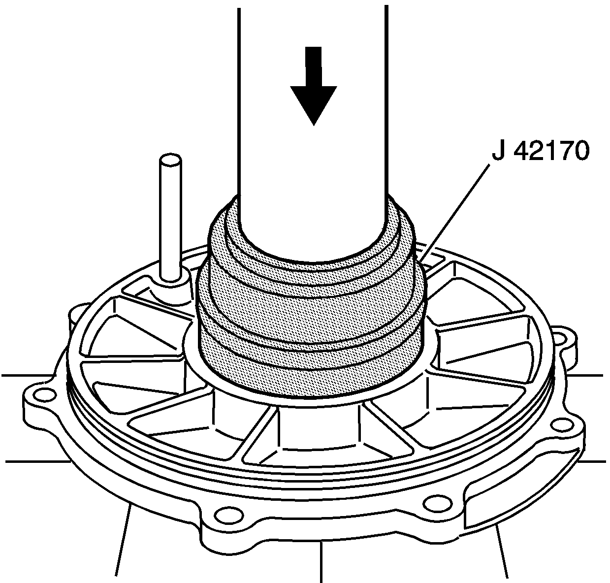
- Use the J 42170 and a hydraulic press in order to install the selected shims (1) and bearing race (2) to the differential housing.
- Use the J 42155 in order to install the differential case into the differential housing.
- Install the right side bearing race (2), and the J 42168-15 (1) onto the differential.
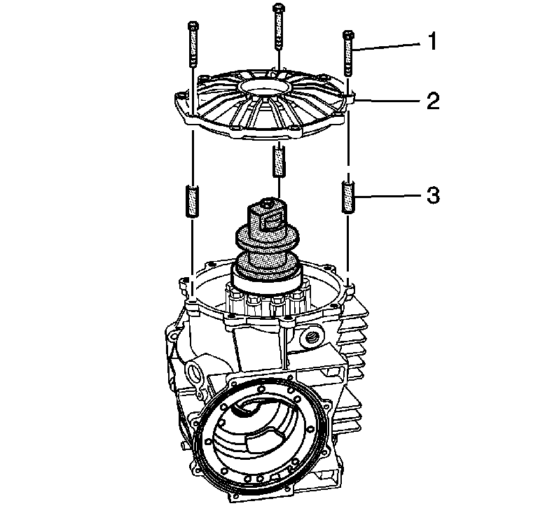
- Install the cover - right (2) and J 42168-16 bolts and spacers to the differential. Position the J 42168-16 bolts and spacers evenly apart.
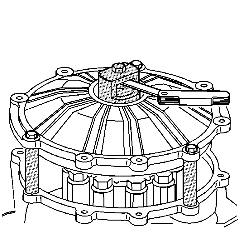
- Insert a feeler gauge into the J 42168-15 and measure the gap. The measured dimension is the right side differential bearing shim size.
- Remove the bolts (1), cover (2), and tools.
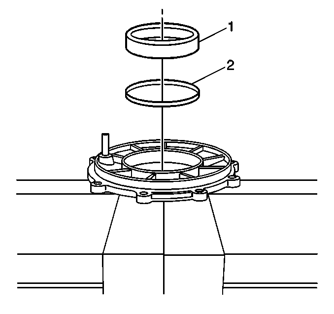
- Install the selected shim (2) and bearing race (1) to the cover - right.
- Install the shim(s) and bearing race into the cover - right using the J 42170 and a hydraulic press. Refer to Rear Axle - Assemble.


Important: Level the tool in order to obtain accurate measurements.
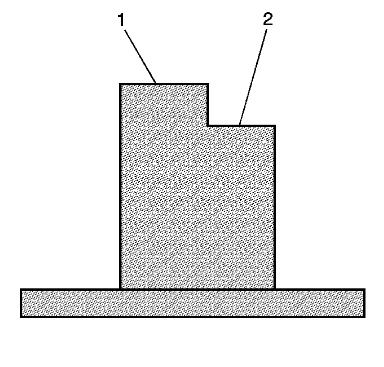
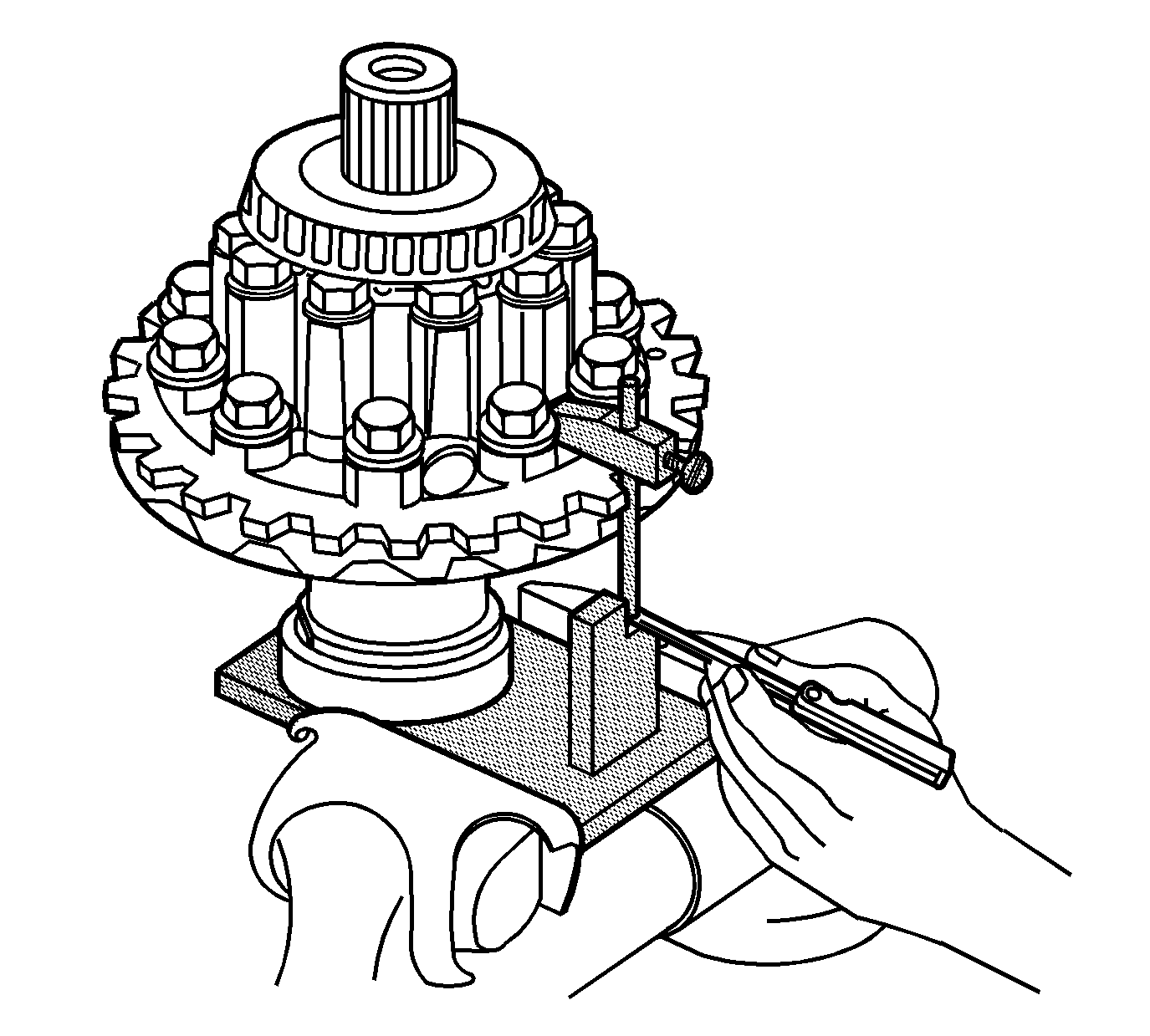
Refer to the applicable calculation table in Spacer and Shim Specifications.

Important: The A2 value is a manufacturing variation between the ring gear and pinion. The A2 value may be higher, lower, or equal to 65.5 mm (2.58 in) (3.15 and 3.42 ratio differentials) or 74.5 mm (2.93 in) (2.73 ratio differential) nominal value. When subtracting the D nominal value from the A2 value, the C3 calculation may compute to a positive, negative, or zero total.


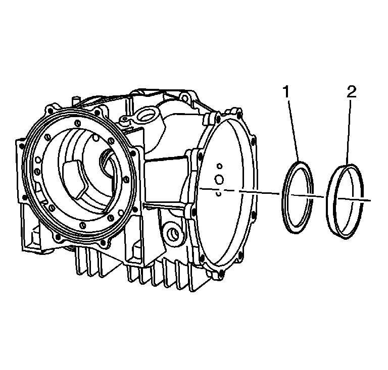
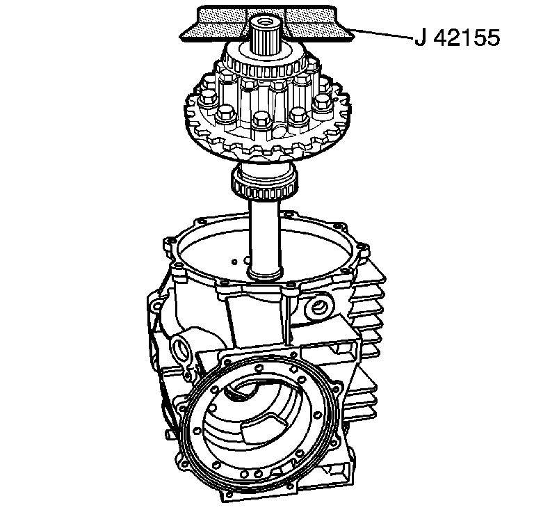
Important: In order to perform the shim selection procedure:
• The oil seal must be removed from the cover - right. • The pinion cartridge must NOT be installed to the differential
case.
Tighten
Tighten the bolts to 25 N·m (18 lb ft).

Spacer and Shim Specifications
Calculations | Example Measurements | Actual Measurements | ||
|---|---|---|---|---|
| Metric | English | Metric | English |
B Nominal value | 5.00 mm | 0.197 in | 5.00 mm | 0.197 in |
B1 Measured value | 3.44 mm | 0.135 in |
|
|
B2 (B nominal value minus B1 = B2) | 1.56 mm | 0.061 in |
|
|
| ||||
A1 Value (taken from ring gear) | 103.03 mm | 4.056 in |
|
|
A Nominal value | 103.00 mm | 4.055 in | 103.00 mm | 4.055 in |
B3 (A1 value minus A nominal = B3) | 0.03 mm | 0.0012 in |
|
|
| ||||
B2 | 1.56 mm | 0.061 in |
|
|
B3 | 0.03 mm | 0.0012 in |
|
|
Pinion shim size (B2 plus B3 = pinion shim) | 1.59 mm | 0.0622 in |
|
|
Calculations | Example Measurements | Actual Measurements | ||
|---|---|---|---|---|
| Metric | English | Metric | English |
B Nominal value | 5.00 mm | 0.197 in | 5.00 mm | 0.197 in |
B1 Measured value | 3.44 mm | 0.135 in |
|
|
B2 (B nominal value minus B1 = B2) | 1.56 mm | 0.061 in |
|
|
| ||||
A1 Value (taken from ring gear) | 102.97 mm | 4.054 in |
|
|
A Nominal value | 103.00 mm | 4.055 in | 103.00 mm | 4.055 in |
B3 (A1 value minus A nominal = B3) | -0.03 mm | -0.0011 in |
|
|
| ||||
B2 | 1.56 mm | 0.061 in |
|
|
B3 | -0.03 mm | -0.0011 in |
|
|
Pinion shim size (B2 plus B3 = pinion shim) | 1.53 mm | 0.0599 in |
|
|
Calculations | Example Measurements | Actual Measurements | ||
|---|---|---|---|---|
| Metric | English | Metric | English |
C Nominal value | 5.00 mm | 0.197 in | 5.00 mm | 0.197 in |
C1 Measured value | 1.19 mm | 0.047 in |
|
|
C2 (C nominal value minus C1 = C2) | 3.81 mm | 0.15 in |
|
|
| ||||
A2 Value (taken from ring gear) | 65.53 mm | 2.579 in |
|
|
D Nominal value | 65.50 mm | 2.58 in | 65.50 mm | 2.58 in |
C3 (A2 value minus D nominal = C3) | 0.03 mm | 0.0012 in |
|
|
| ||||
C2 | 3.81 mm | 0.15 in |
|
|
C3 | 0.03 mm | 0.0012 in |
|
|
Left side case shim (C2 plus C3 = left side shim) | 3.84 mm | 0.1512 in |
|
|
Calculations | Example Measurements | Actual Measurements | ||
|---|---|---|---|---|
| Metric | English | Metric | English |
C Nominal value | 5.00 mm | 0.197 in | 5.00 mm | 0.197 in |
C1 Measured value | 1.19 mm | 0.047 in |
|
|
C2 (C nominal value minus C1 = C2) | 3.81 mm | 0.15 in |
|
|
| ||||
A2 Value (taken from ring gear) | 65.47 mm | 2.577 in |
|
|
D Nominal value | 65.50 mm | 2.58 in | 65.50 mm | 2.58 in |
C3 (A2 value minus D nominal = C3) | -0.03 mm | -0.0012 in |
|
|
| ||||
C2 | 3.81 mm | 0.15 in |
|
|
C3 | -0.03 mm | -0.0012 in |
|
|
Left side case shim (C2 plus C3 = left side shim) | 3.78 mm | 0.1498 in |
|
|
Calculations | Example Measurements | Actual Measurements | ||
|---|---|---|---|---|
| Metric | English | Metric | English |
C Nominal value | 5.00 mm | 0.197 in | 5.00 mm | 0.197 in |
C1 Measured value | 1.19 mm | 0.047 in |
|
|
C2 (C nominal value minus C1 = C2) | 3.81 mm | 0.15 in |
|
|
| ||||
A2 Value (taken from ring gear) | 74.53 mm | 2.934 in |
|
|
D Nominal value | 74.50 mm | 2.933 in | 74.50 mm | 2.933 in |
C3 (A2 value minus D nominal = C3) | 0.03 mm | 0.0012 in |
|
|
| ||||
C2 | 3.81 mm | 0.15 in |
|
|
C3 | 0.03 mm | 0.0012 in |
|
|
Left side case shim (C2 plus C3 = left side shim) | 3.84 mm | 0.1512 in |
|
|
Calculations | Example Measurements | Actual Measurements | ||
|---|---|---|---|---|
| Metric | English | Metric | English |
C Nominal value | 5.00 mm | 0.197 in | 5.00 mm | 0.197 in |
C1 Measured value | 1.19 mm | 0.047 in |
|
|
C2 (C nominal value minus C1 = C2) | 3.81 mm | 0.15 in |
|
|
| ||||
A2 Value (taken from ring gear) | 74.47 mm | 2.932 in |
|
|
D Nominal value | 74.50 mm | 2.933 in | 74.50 mm | 2.933 in |
C3 (A2 value minus D nominal = C3) | -0.03 mm | -0.0012 in |
|
|
| ||||
C2 | 3.81 mm | 0.15 in |
|
|
C3 | -0.03 mm | -0.0012 in |
|
|
Left side case shim (C2 plus C3 = left side shim) | 3.78 mm | 0.1498 in |
|
|
