The fuel metering system consists of the following components:
| • | The fuel supply components, including: |
| - | A modular fuel pump and sender assembly. |
| - | A siphon jet pump and sender assembly. |
| - | The fuel pipes and hoses. |
| • | The fuel pump electrical circuit. |
| • | The fuel rail assembly, including: |
| - | The fuel pressure regulator. |
| • | The throttle body assembly, including: |
| - | The Throttle Position (TP) sensor. |
Fuel Pump Electrical Circuit
When the ignition switch is in the ON position (before engaging the
starter), the PCM energizes the fuel pump relay for two seconds, causing the
fuel pump to pressurize the fuel system. If the PCM does not receive ignition
reference pulses (engine cranking or running) within two seconds, it shuts
OFF the fuel pump relay, causing the fuel pump to stop.
Fuel Rail Assembly

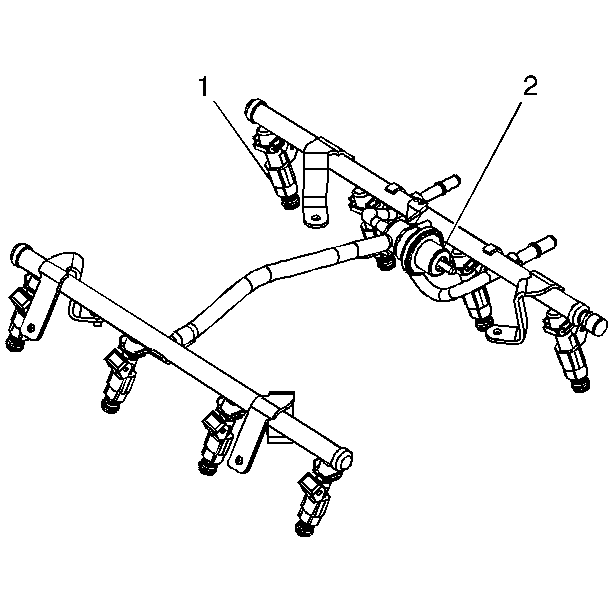
The fuel rail assembly attaches to the engine intake manifold. The fuel rail
assembly performs the following functions:
| • | It positions the injectors (1) in the intake manifold. |
| • | It distributes fuel evenly to the injectors. |
| • | It integrates the fuel pressure regulator (2) into the fuel metering
system. |
Fuel Injectors
The top-feed fuel injector assembly is a solenoid operated device, controlled
by the PCM, that meters pressurized fuel to a single engine cylinder. The
PCM energizes the injector solenoid, which opens a ball valve, allowing fuel
to flow past the ball valve, and through a recessed flow director plate. The
director plate has multiple machined holes that control the fuel flow, generating
a conical spray pattern of finely atomized fuel at the injector tip. Fuel
is directed at the intake valve, causing it to become further atomized and
vaporized before entering the combustion chamber. An injector stuck partly
open can cause a loss of pressure after engine shutdown. Consequently, long
cranking times would be noticed on some engines.
Fuel Pressure Regulator Assembly

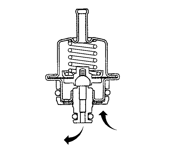
The fuel pressure regulator
is a diaphragm operated relief valve with fuel pump pressure on one side and
regulator spring pressure on the other side. The fuel pressure regulator is
vented to atmosphere. A software bias is used to compensate injector on-time
because the regulator is not referenced to manifold vacuum. The injector pulse
width varies with the signal from the MAP sensor. With the ignition ON and
the engine OFF, system fuel pressure at the pressure test connection should
read 380-420 kPa (55-61 psi). If the pressure is
too low, poor performance could result. If the pressure is too high, excessive
odor and a Diagnostic Trouble Code (DTC) P0132, P0152, P0172 or P0175 may
result. The Fuel System Diagnosis table has information on diagnosing fuel
pressure conditions.
Throttle Body Assembly
The throttle body assembly attaches to the intake manifold. The throttle
body controls air flow into the engine, thereby controlling engine output.
The air control valve mounted on the throttle body opens the throttle valve
within the throttle body. Engine coolant flows through the coolant cavity
on the bottom of the throttle body in order to prevent throttle valve icing
during cool weather operation. The throttle body also provides the location
for mounting the Throttle Position (TP) sensor.
Throttle Position (TP) Sensor
The TP sensor is mounted on the side of the throttle body opposite the
air control valve. The TP sensor senses the throttle valve angle and relays
that information to the PCM. Knowledge of throttle angle is needed by the
PCM to generate the required injector control signals (pulses).


