Removal Procedure
Tools Required
| • | J 28467-B Universal Engine Support Fixture |
| • | J 33432-A Transverse Leaf Spring Compressor |
| • | J 41803 Engine Support Fixture |
| • | J 42188 Ball Joint Separator |
- Disconnect the negative battery cable.
- Remove the generator from the accessory mounting bracket. Refer to Generator Replacement in Engine Electrical.
- Install J 41803 andJ 28467-B and support the engine.
- Raise and support the vehicle. Refer to Lifting and Jacking the Vehicle in General Information.
- Remove the tire and wheel assemblies. Refer to Tire and Wheel Removal and Installation in Tires and Wheels.
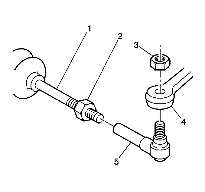
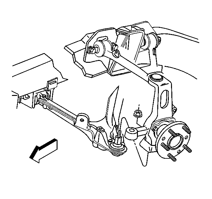
- Loosen the steering linkage outer tie rod nuts (3). Do not remove the nuts.
- Install J 42188 on the left steering linkage outer tie rod end.
- Separate the left steering linkage outer tie rod (5) from the steering knuckle (4).
- Remove J 42188 and the steering linkage tie rod nut from the left steering linkage tie rod.
- Install J 42188 on the right steering linkage outer tie rod end.
- Separate the right steering linkage outer tie rod from the steering knuckle.
- Remove J 42188 and the steering linkage tie rod nut from the right steering linkage outer tie rod.
- If equipped, disconnect the real time dampening (RTD)sensor links.
- Support the lower control arms with jack stands.
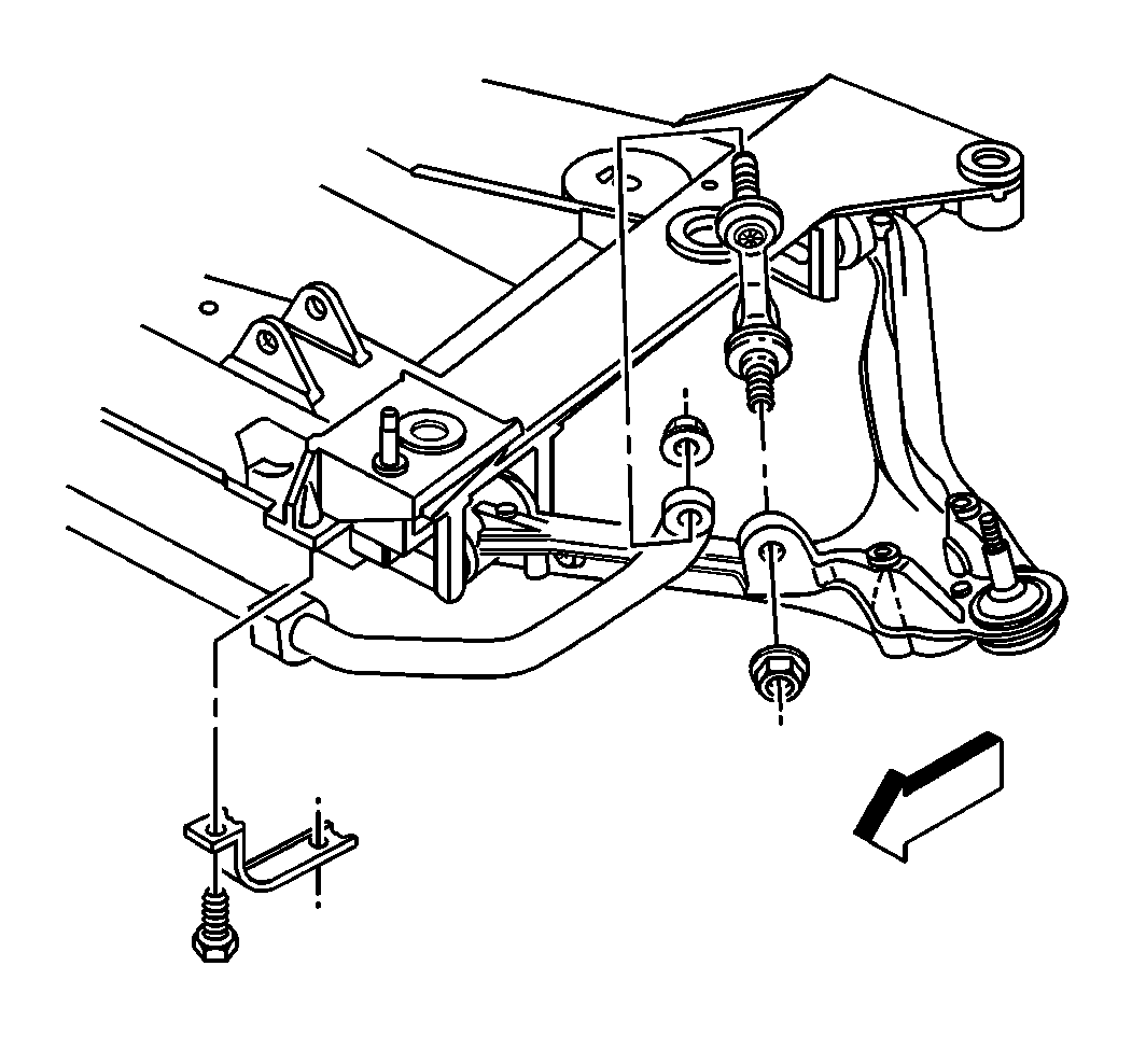
- Disconnect the stabilizer bar links from the lower control arms.
- Remove the stabilizer bar from the vehicle. Refer to Stabilizer Shaft Replacement .
- Disconnect the intermediate shaft lower coupling from the steering gear. Refer to Intermediate Steering Shaft Replacement in Steering Wheel and Column-Tilt.
- Remove the bolts from the brake pressure modulator valve bracket, if equipped.
- Reposition the electronic brake control module/brake pressure modulator valve (EBTCM/BPMV) and bracket away from the crossmember, if equipped.
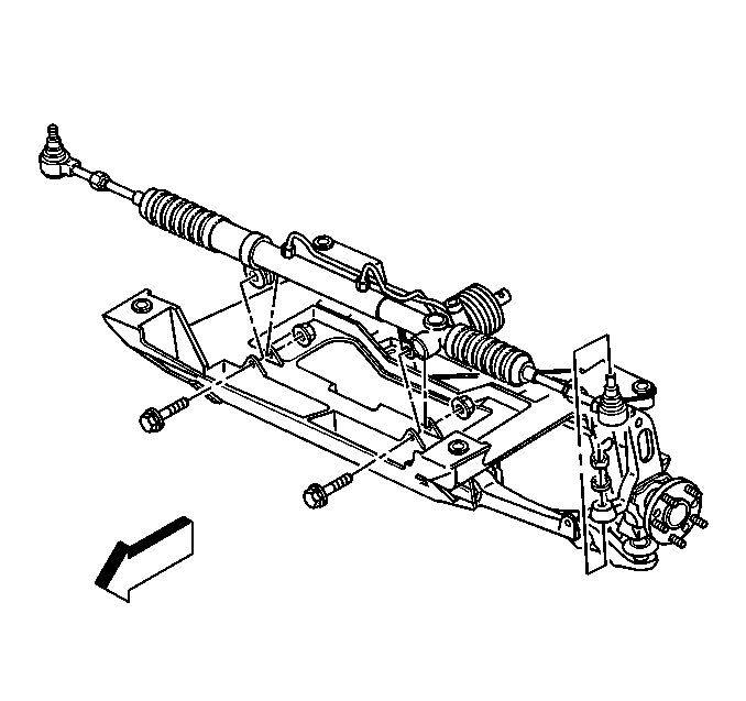
- Remove the power steering gear mounting bolts.
- Disconnect the power steering fluid cooler from the crossmember.
- Lift the power steering gear off of the crossmember and support.
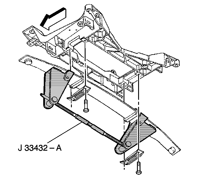
- Install the transverse leaf spring compressor J 33432-A .
- Compress the transverse leaf spring.
- Loosen the lower arm ball joint stud nuts. Do not remove the nuts.
- Install J 42188 to the lower right ball joint.
- Separate the ball joint stud from the steering knuckle.
- Remove the J 42188 and the ball joint stud nut.
- Install J 42188 to the lower left ball joint.
- Separate the ball joint stud from the steering knuckle.
- Remove the J 42188 and the ball joint stud nut.
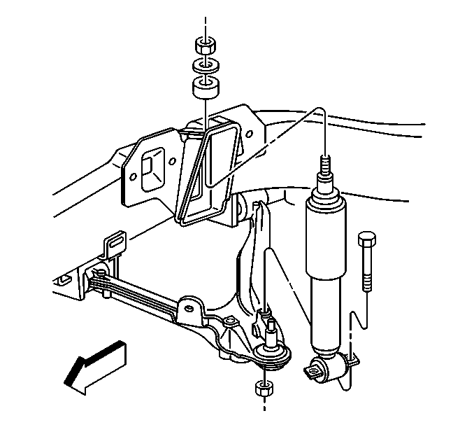
- Disconnect the lower shock absorber bolts from the lower control arms.
- Disconnect the lower control arms from the steering knuckles.
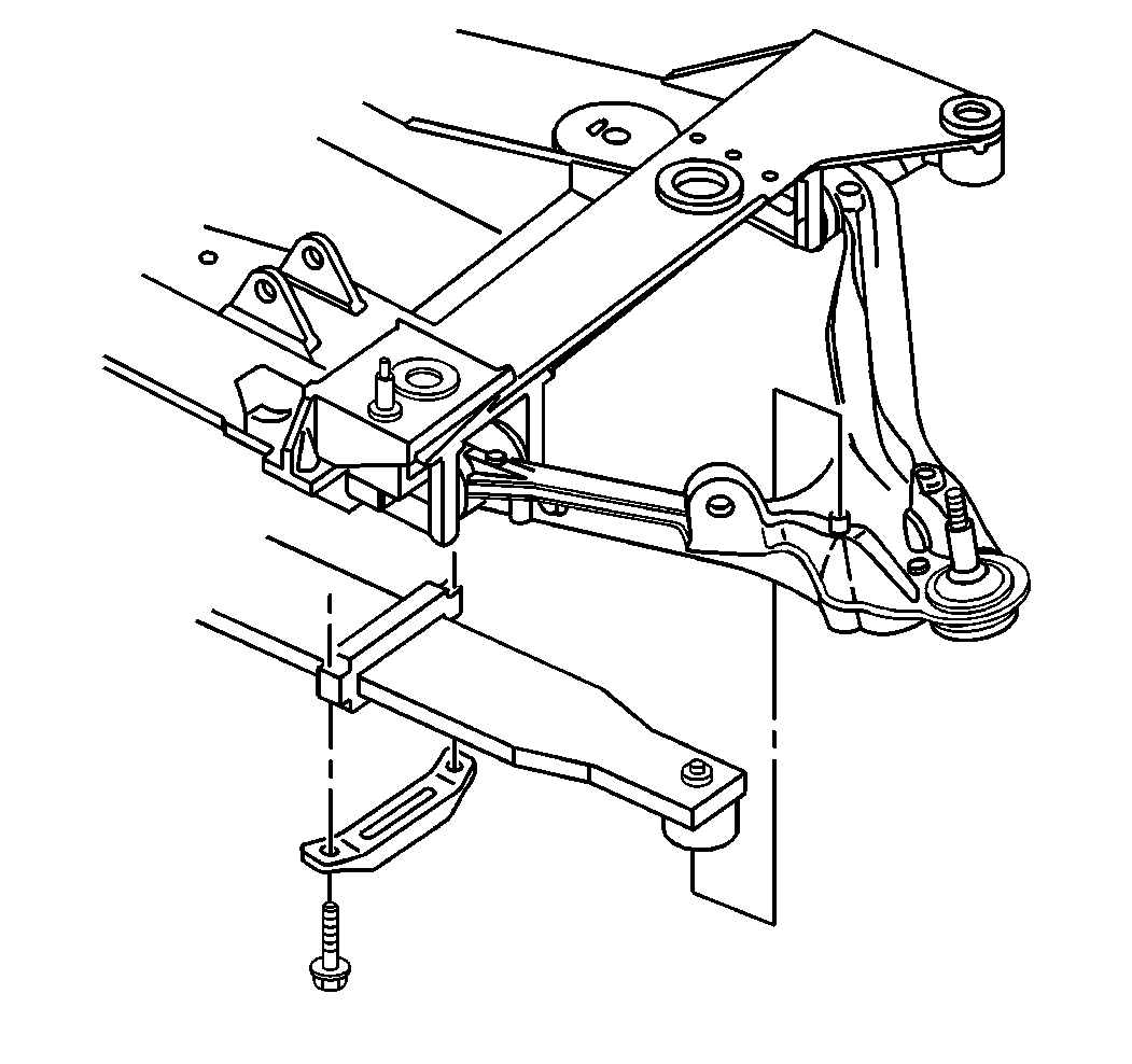
- Remove the left transverse spring mounting bracket.
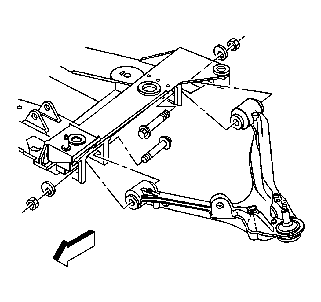
- Remove the lower left control arm from the vehicle.
- Remove the right transverse spring retainer.
- Keeping J 33432-A attached to the spring, remove the transverse spring from the vehicle.
- Remove the lower right control arm from the crossmember if necessary.
- Place a pole jack under the crossmember.
- Remove the engine mount lower nuts. Refer to Engine Mount Replacement in Engine Mechanical.
- Remove the crossmember mounting nuts.
- Disconnect the wiring harness from the crossmember.
- Disconnect the brake pipe from the crossmember.
- Lower the crossmember out of the vehicle.
Caution: Unless directed otherwise, the ignition and start switch must be in the OFF or LOCK position, and all electrical loads must be OFF before servicing any electrical component. Disconnect the negative battery cable to prevent an electrical spark should a tool or equipment come in contact with an exposed electrical terminal. Failure to follow these precautions may result in personal injury and/or damage to the vehicle or its components.


Installation Procedure
- Raise the crossmember to the vehicle.
- Install new crossmember mounting nuts.
- Install the engine mount lower nuts. Refer to Engine Mount Replacement in Engine Mechanical.
- Connect the wiring harness to the crossmember.
- Connect the brake pipe to the crossmember.
- Install the lower left control arm.
- Install the transverse spring to the crossmember.
- Install the left transverse retainer.
- Install the lower right control arm, if removed.
- Install the right transverse retainer.
- Remove the transverse spring compressor J 33432-A .
- Remove the transmission jack from the crossmember.
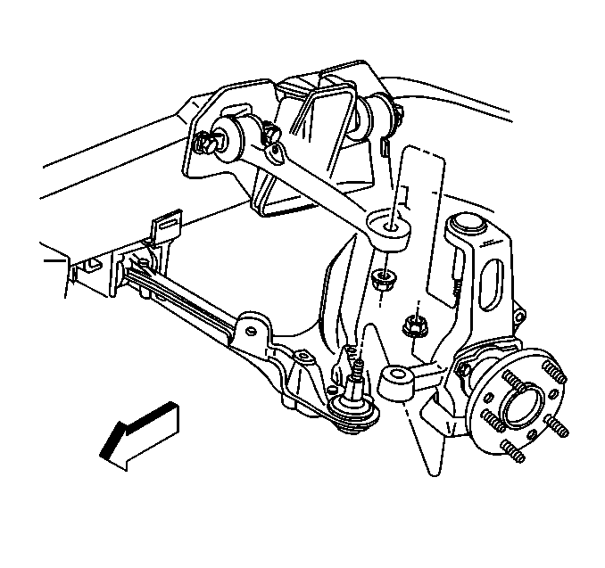
- Install the lower control arm ball joint studs into the steering knuckles.
- Tighten the lower control arm ball joint stud nuts to 20 N·m (15 lb ft) to seat the ball joint stud.
- Turn the ball joint stud nut an additional 210 degrees
- Check the ball joint stud nut for a minimum final torque of 70 N·m (52 lb ft).
- Install the shock absorbers to the lower control arms.
- Install the power steering gear to the crossmember.
- Install the bolts to the brake pressure modulator valve bracket, if equipped.
- Connect the intermediate shaft onto the steering gear. Refer to Intermediate Steering Shaft Replacement in Steering Wheel and Column-Tilt.
- Center the power steering gear.
- Install the steering linkage outer tie rod into the steering knuckles. Refer to Rack and Pinion Outer Tie Rod End Replacement in Power Steering System.
- If equipped, connect the RTD sensors.
- Install the stabilizer shaft onto the crossmember.
- Install the stabilizer shaft links onto the lower control arms.
- Install the tire and wheel assemblies. Refer to Tire and Wheel Removal and Installation in Tires and Wheels.
- Lower the vehicle.
- Remove J 41803 andJ 28467-B from the engine.
- Install the generator. Refer to Generator Replacement in Engine Electrical.
- Connect the negative battery cable.
- Program the Transmitters. Refer to Transmitter Programming/Synchronization in Keyless Entry.
- Perform a vehicle front end alignment. Refer to Wheel Alignment Measurement in Wheel Alignment.
| 1.1. | Align the crossmember dowel pins to the frame rails. |
| 1.2. | Align the engine mount studs. |
Notice: Use the correct fastener in the correct location. Replacement fasteners must be the correct part number for that application. Fasteners requiring replacement or fasteners requiring the use of thread locking compound or sealant are identified in the service procedure. Do not use paints, lubricants, or corrosion inhibitors on fasteners or fastener joint surfaces unless specified. These coatings affect fastener torque and joint clamping force and may damage the fastener. Use the correct tightening sequence and specifications when installing fasteners in order to avoid damage to parts and systems.
Tighten
Tighten the new crossmember mounting nuts to 110 N·m (81 lb ft).


Tighten
Tighten the transverse spring retainer bolts to 62 N·m
(46 lb ft).
Tighten

Tighten
Tighten the shock absorber nuts to 28 N·m (21 lb ft).

Tighten
Tighten the power steering gear mounting bolts to 100 N·m
(74 lb ft).
Tighten
Tighten the bolts to the brake pressure modulator valve bracket to 27 N·m
(20 lb ft), if equipped.


Tighten
Tighten the stabilizer shaft insulator clamp bolts to 58 N·m
(43 lb ft).
Tighten
Tighten the stabilizer shaft link nuts to 60 N·m (44 lb ft).
Tighten
Tighten the negative battery cable to 15 N·m (11 lb ft).
