- Install the bearing housing snap ring, front bearing, and snap ring onto the hub.
- Install the rear bearing and snap ring onto the hub.
- Install the NEW O-rings into the bearing housing.
- Install the hub and bearings assembly into the bearing housing.
- Install the snap ring (1) into the groove of the bearing housing.
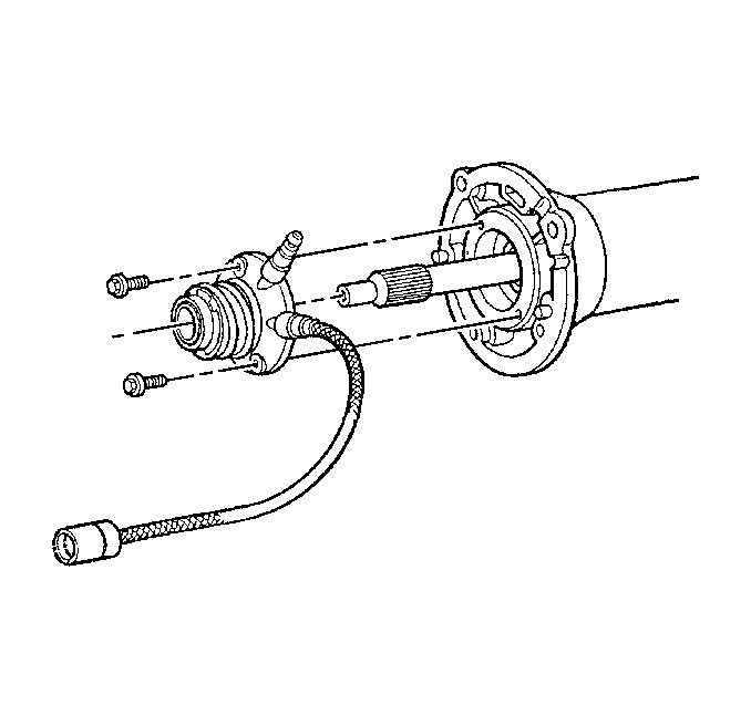
- Insert the flexplate spindle into the hub (automatic transmission).
- Apply threadlock GM P/N 12345382 or equivalent to the threads of the bolt.
- Install the bolt and washer through the hub and to the flexplate spindle.
- Install NEW pilot bushings into the hub (if removed).
- Apply threadlock GM P/N 12345382 or equivalent to the threads of the coupling bolts.
- Install the rear coupling, bolts, and washers to the propeller shaft.
- Install the bearing housing assembly, bolts, and washers to the rear coupling.
- Install the front coupling, bolts, and washers to the propeller shaft.
- Install the bearing onto the input shaft.
- Install the snap ring into the groove of the input shaft.
- Install a NEW slinger washer onto the input shaft.
- Install the input shaft, bolts, and washers to the front coupling.
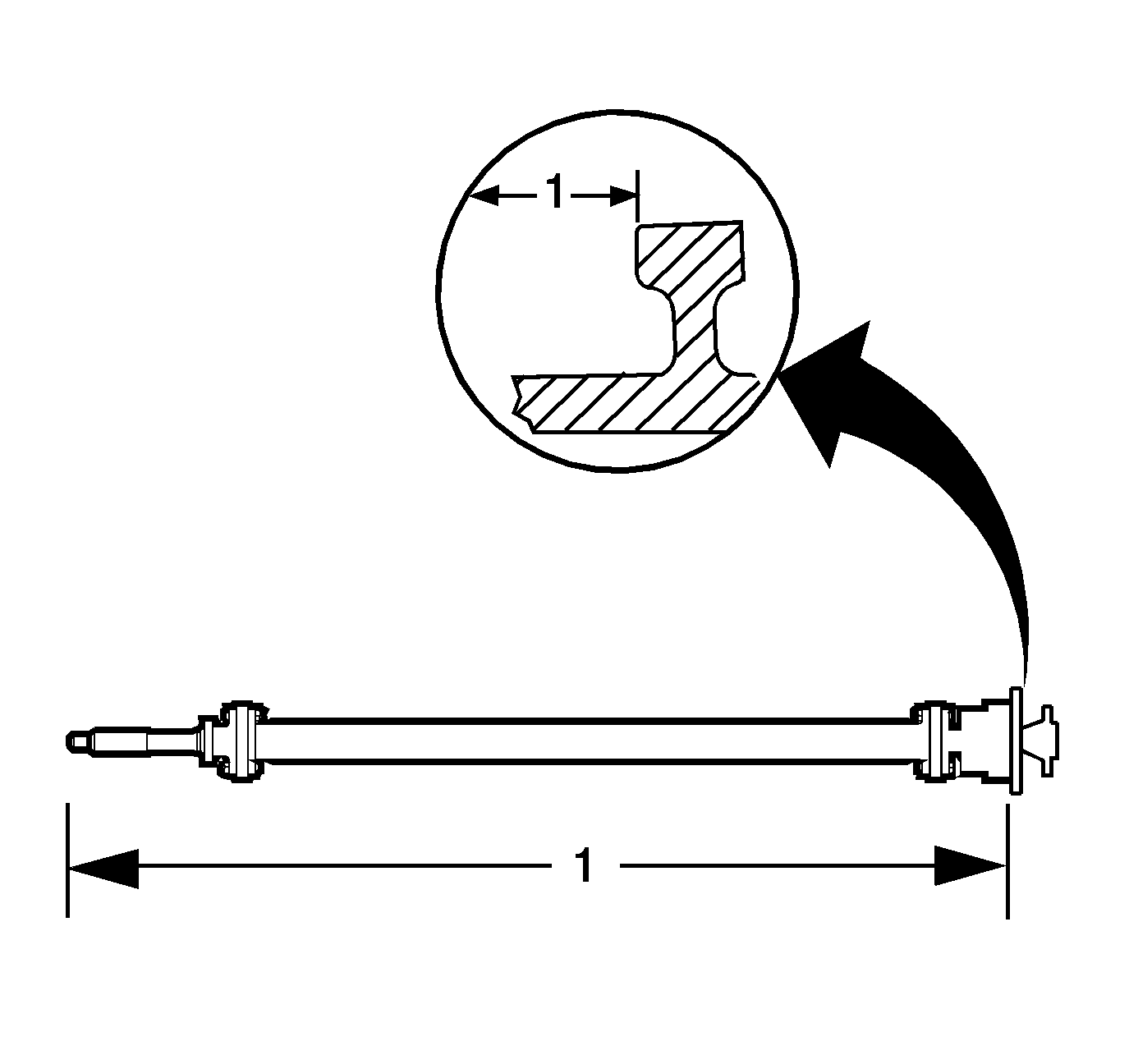
- Measure the distance (1) from the end of the input shaft to the flange on the bearing housing (automatic transmission).
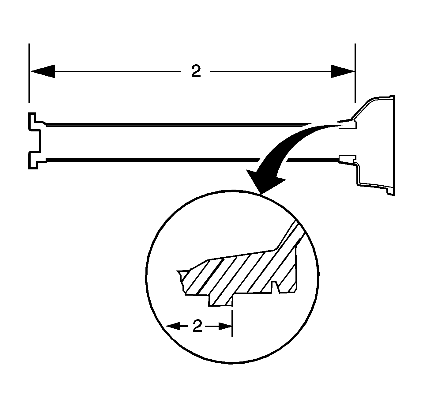
- Measure the distance (2) from the driveline tube front bellhousing flange to the bearing housing flange (automatic transmission).
- Subtract distance (2) from distance 1.
- Record the dimension.
- Lubricate the NEW driveline tube front O-ring with clean engine oil.
- Install the O-ring into the front of the driveline tube.
- Install the propeller shaft assembly into the driveline tube.
- Remove the alignment studs and install the bearing housing bolts and washers.
- Measure the distance (3) from the end of the input shaft to the driveline tube front bellhousing flange (automatic transmission).
- Install the flex plate and bolts (automatic transmission).
- Install the clutch actuator and bolts (manual transmission).

Important: Do not separate the input shaft, propeller shaft, couplings, or bearing housing assembly (unless required). These components are balanced as an assembly. Disassembly and improper reassembly of the components may cause vehicle driveline vibration.
If the input shaft, couplings, propeller shaft, or bearing housing assembly must be separated, the components must be marked prior to disassembly. During assembly, the components must be returned to their original position and location.


Align the marks on the hub and flexplate spindle for proper assembly.

Notice: Use the correct fastener in the correct location. Replacement fasteners must be the correct part number for that application. Fasteners requiring replacement or fasteners requiring the use of thread locking compound or sealant are identified in the service procedure. Do not use paints, lubricants, or corrosion inhibitors on fasteners or fastener joint surfaces unless specified. These coatings affect fastener torque and joint clamping force and may damage the fastener. Use the correct tightening sequence and specifications when installing fasteners in order to avoid damage to parts and systems.
Tighten
Tighten the bolt to 50 N·m (37 lb ft).

Important: If the coupling orientation mark has been lost during the cleaning or disassembly process, the coupling MUST be installed with the directional arrow pointed toward the flange to which it mounts.
Tighten
Tighten the coupling bolts to 70 N·m (52 lb ft).

Important: If the coupling orientation mark has been lost during the cleaning or disassembly process, the coupling MUST be installed with the directional arrow pointed toward the flange to which it mounts.
Tighten
Tighten the coupling bolts to 70 N·m (52 lb ft).
Important: If the coupling orientation mark has been lost during the cleaning or disassembly process, the coupling MUST be installed with the directional arrow pointed toward the flange to which it mounts.
Tighten
Tighten the coupling bolts to 70 N·m (52 lb ft).
Install the bearing until completely seated against the flange of the input shaft.
A properly installed slinger washer will have a gap of 1.5-2.5 mm (0.059-0.098 in) between the washer and the bearing face.
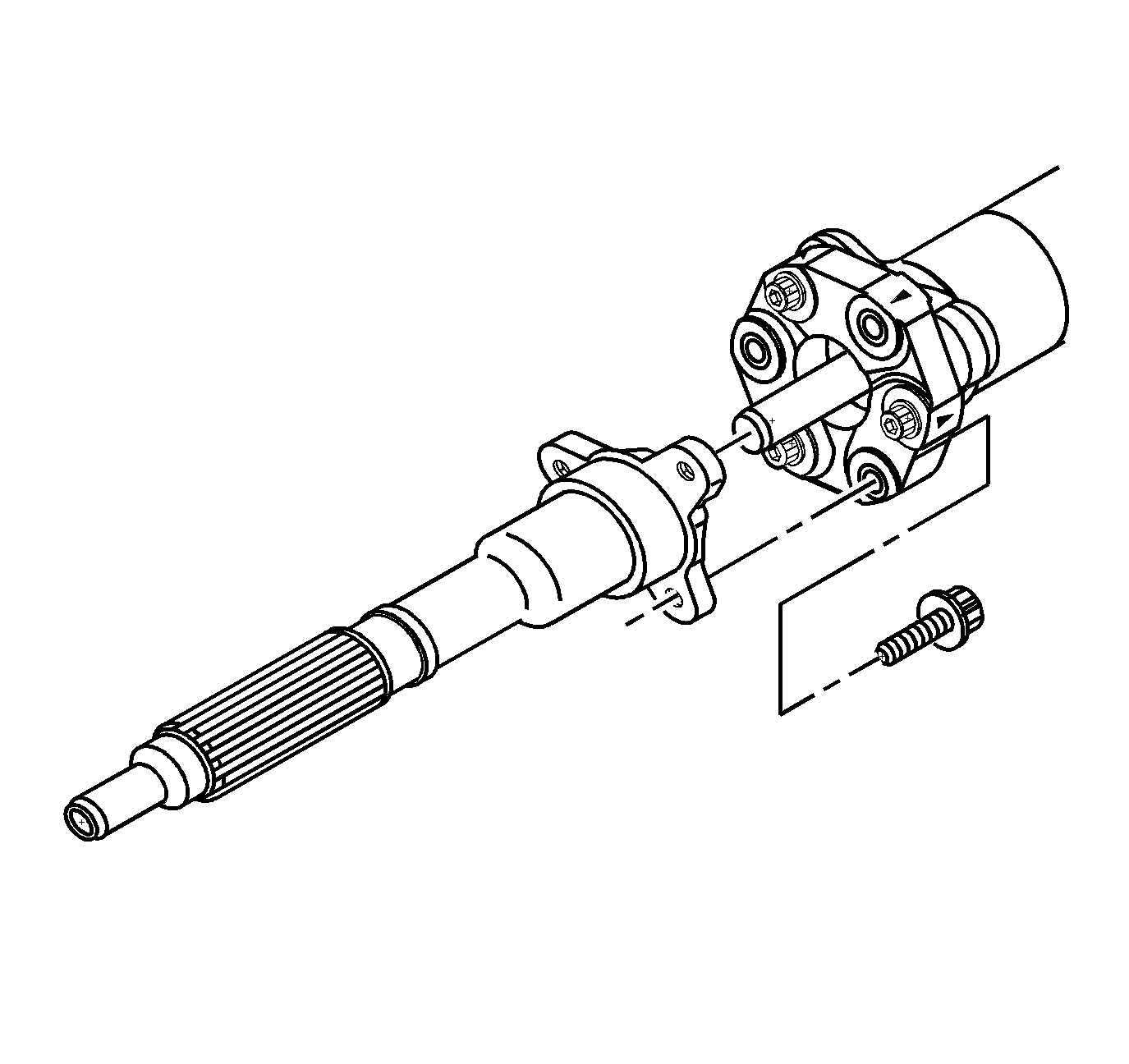
Important: If the coupling orientation mark has been lost during the cleaning or disassembly process, the coupling MUST be installed with the directional arrow pointed toward the flange to which it mounts.
Tighten
Tighten the coupling bolts to 70 N·m (52 lb ft).

During installation, lift the front of the input shaft to avoid damage to the slinger washer.
Use two M10-1.5 mm x 100 mm studs to assist in alignment of the bearing housing, bellhousing, and driveline tube.

Tighten
Tighten the bearing housing bolts to 65 N·m (48 lb ft).
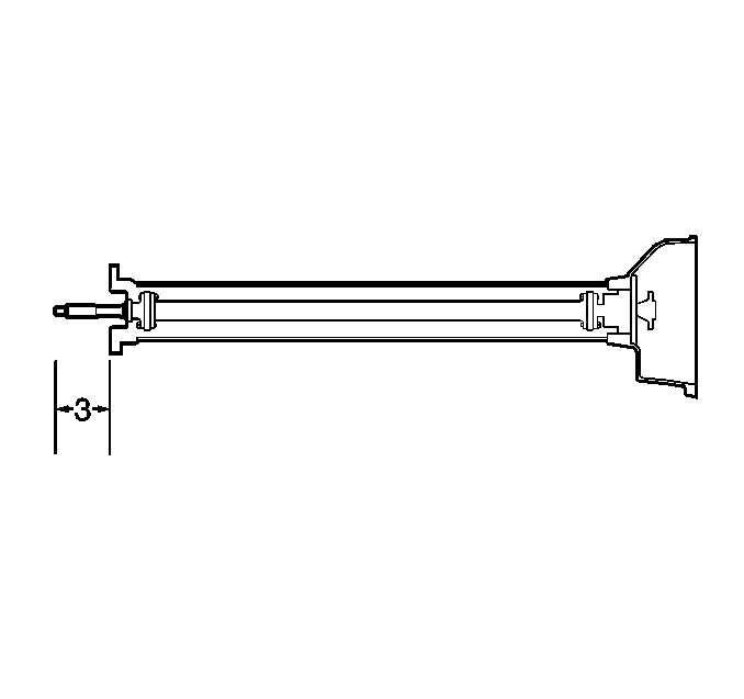
Important: The propeller shaft assembly must be checked for proper installation into the driveline tube (automatic transmission). When the propeller shaft assembly is installed into the driveline tube, the couplings may compress and not properly position the input shaft.
The actual distance (3) must be equal to or within 2 mm (0.079 in) of the recorded dimension.
| 26.1. | If the actual distance is not within specifications, use a heat gun and heat the driveline support tube at the front bearing location. |
| 26.2. | Tap on the rear of the propeller shaft assembly or pull on the input shaft until it has reached the proper position. |

Tighten
Tighten the flex plate bolts to 50 N·m (37 lb ft).
Tighten
Tighten the clutch actuator bolts to 12 N·m (106 lb in).
