For 1990-2009 cars only
Disassembly Procedure
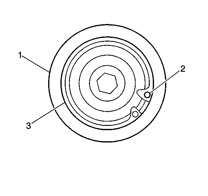
- Squeeze the ends (2) (4) of the retaining ring (3) together.
- Remove the retaining ring (3) from the housing (1).
- Remove the drive shaft (5) and the ball bearing assembly (4) from the housing.
- Perform the following steps if clearance exists between the drive shaft shoulder (2) the ball bearing inner race (3):
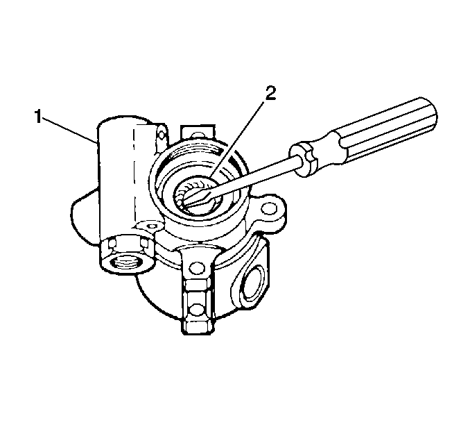
- Use a screwdriver to pry the drive shaft seal (2) from the pump housing assembly (1).
- Clean all the parts with power steering fluid.
- Dry all of the parts.
- Inspect the following parts for scoring or pitting:
- Replace the parts that have scoring or pitting.
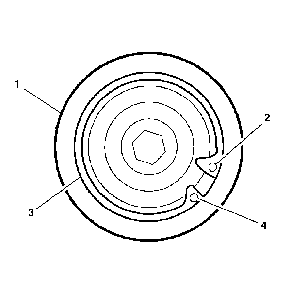
Important: Note the position of the large lug to be sure the beveled side of the retaining ring (3) is properly located.
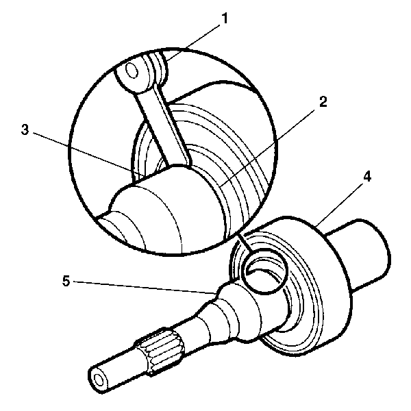
| 4.1. | Use a feeler gage in order to measure the clearance between the drive shaft shoulder (2) and the ball bearing inner race (3) before ball bearing assembly removal. |
| 4.2. | Remove the ball bearing assembly (4) from the drive shaft (5). |
| • | The drive shaft |
| • | The splines |
| • | The ball bearing assembly |
Assembly Procedure
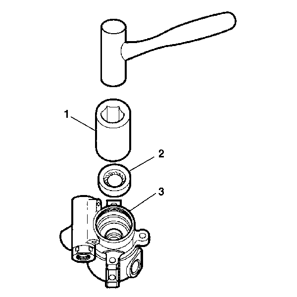
- Tap on the suitable socket (1) with a hammer in order to install the seal (2) into the pump housing (3).
- Lubricate the new drive shaft seal (2) with power steering fluid.
- Perform the following steps to install the ball bearing (3) to the drive shaft (2):
- Install the retaining ring (3) to the housing (1).
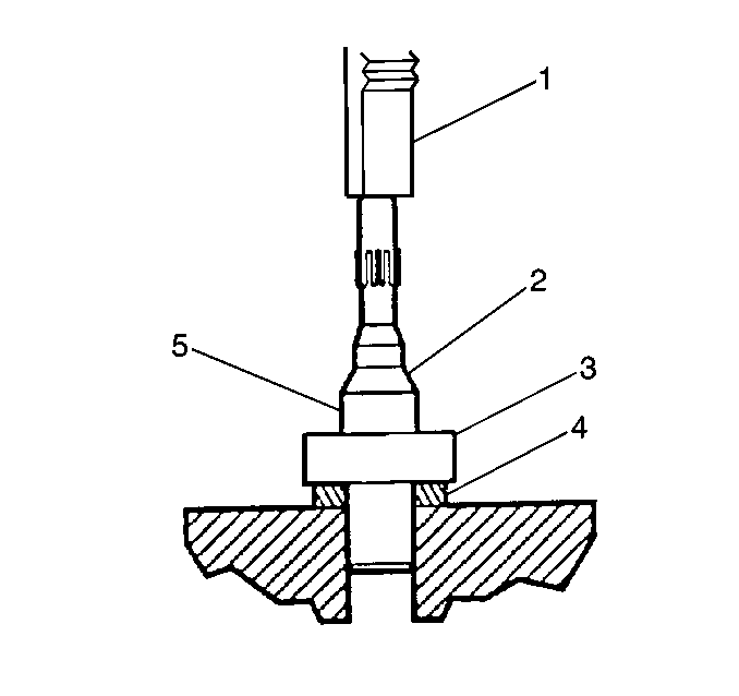
| 3.1. | If the clearance was measured during disassembly, press the ball bearing assembly (3) to the clearance measurement. If the clearance was not measured during disassembly, press the ball bearing (3) to the shoulder (5) of the drive shaft (2). |
| 3.2. | Install the drive shaft (5) and the ball bearing (3) into the housing assembly. |
| 3.3. | Rotate the drive shaft (5) so that the shaft serration (4) engages with the pump rotor. |
