Temperature Actuator Replacement LH
Removal Procedure
- Remove the front floor kick-up panel. Refer to Kick-Up Panel Replacement - Front Floor in Interior Trim.
- Remove the cover from the I/P electrical center.
- Remove the HVAC CON (HVAC controls) MiniFuse® #27 from the I/P electrical center.
- Remove the I/P upper trim pad. Refer to Instrument Panel Upper Trim Pad Replacement in Instrument Panel, Gauges and Console.
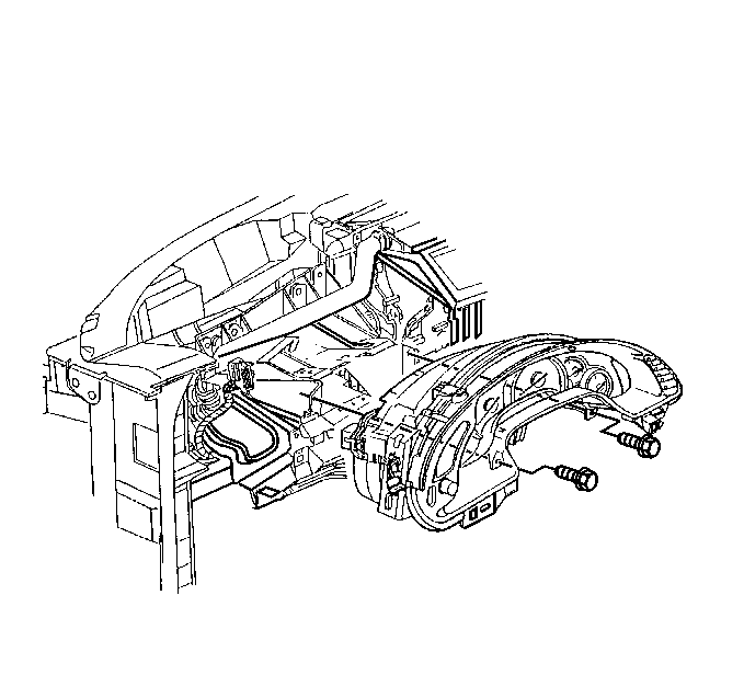
- Remove the instrument panel cluster (IPC) to steering column bracket retaining screws.
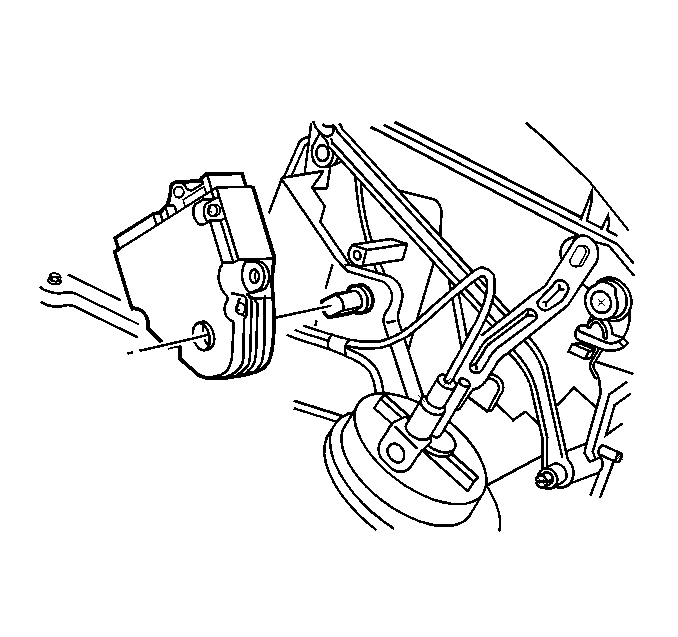
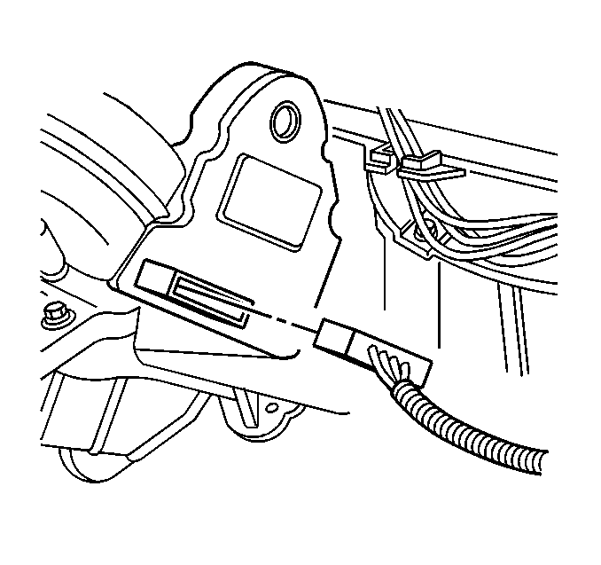
- Reposition the IPC to better access the LH temperature valve electric actuator.
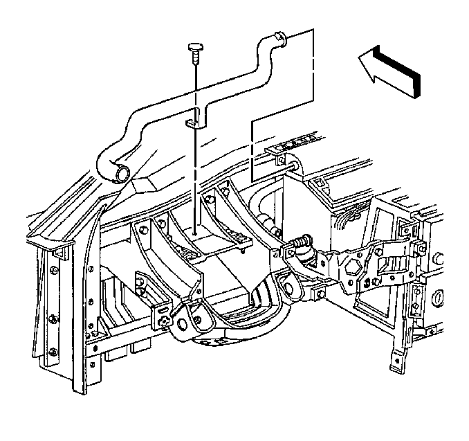
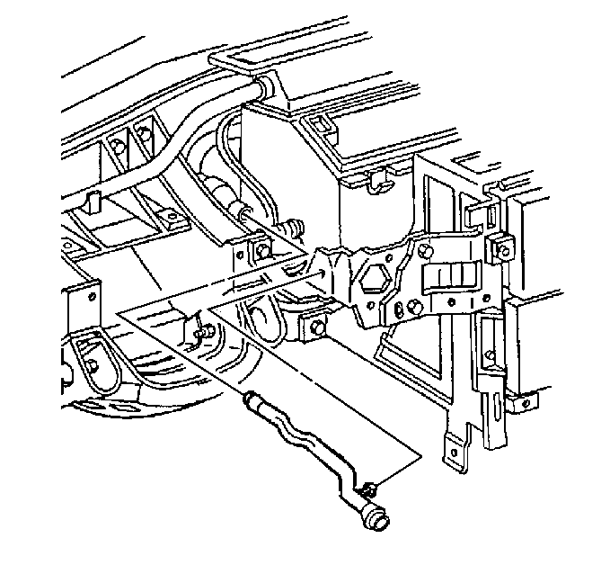
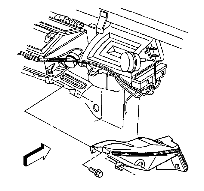
- Remove the LH side window defogger outlet duct - lower.
- Remove the inside air temperature sensor aspirator duct.
- Remove the inside air temperature sensor aspirator duct muffler.
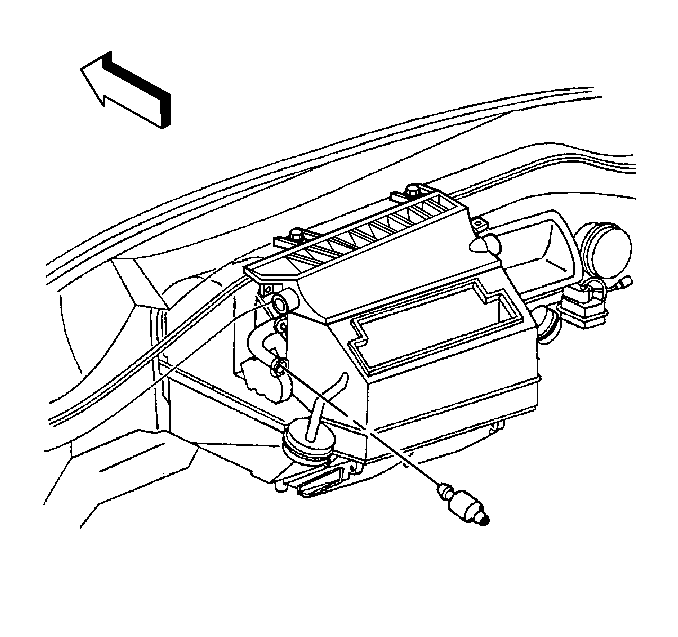
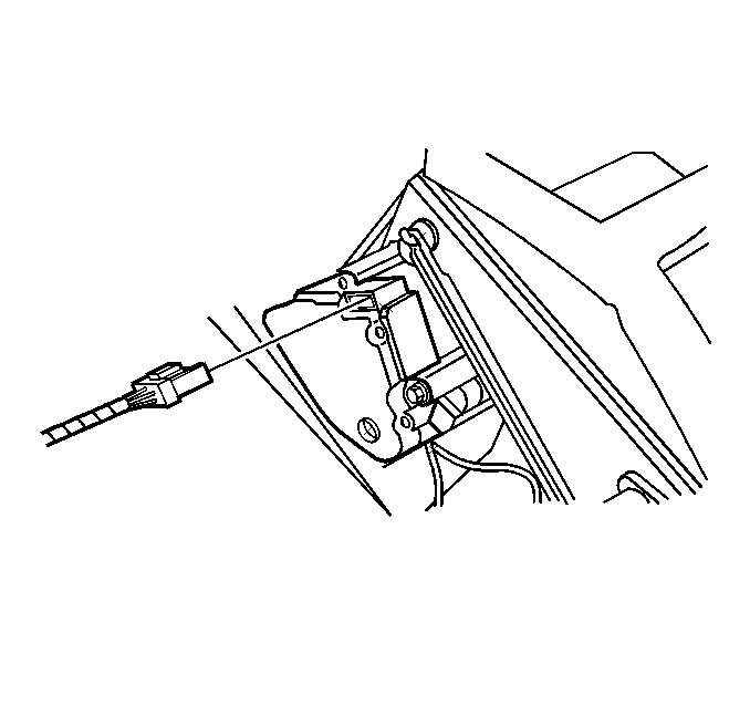
- Disconnect the electrical connector from the LH temperature valve electric actuator.
- Remove the two screws retaining the LH temperature valve electric actuator.
- Remove the electric actuator.
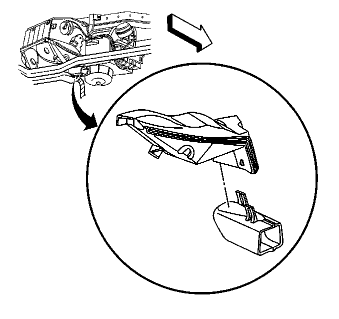
| 7.1. | Remove the push-in retainer. |
| 7.2. | Use a twisting motion to release the defogger outlet duct - lower from the windshield defroster duct, then from the defogger outlet duct - upper. |
| 8.1. | Depress the duct retaining tab and remove the duct from the ignition switch housing bracket. |
| 8.2. | Use a twisting motion to release the duct from the duct muffler. |
Use a twisting motion to release the duct muffler.
Installation Procedure
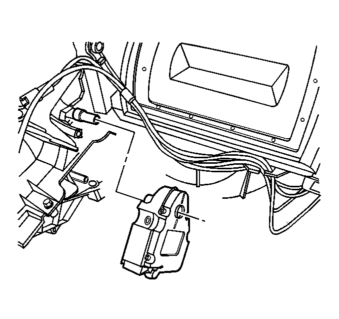
- Position the LH temperature valve electric actuator, then align the slots in the electric actuator driver to the flats on the LH temperature valve shaft.
- Slide the electric actuator driver onto the shaft, while aligning the actuator locating hole to the forward alignment pin on the HVAC module case.
- Install the two LH temperature valve electric actuator retaining screws.
- Connect the electrical connector to the electric actuator.
- Install the inside air temperature sensor aspirator duct muffler.
- Install the inside air temperature sensor aspirator duct.
- Install the LH side window defogger outlet duct - lower.
- Install the instrument panel cluster (IPC) into position.
- Install the IPC to steering column bracket retaining screws.
- Install the I/P upper trim pad. Refer to Instrument Panel Upper Trim Pad Replacement in Instrument Panel, Gauges and Console.
- Install the HVAC CON (HVAC controls) MiniFuse® #27 to the I/P electrical center.
- Install the cover to the I/P electrical center.
- Install the front floor kick-up panel. Refer to Kick-Up Panel Replacement - Front Floor in Interior Trim.
The actuator driver should completely seat onto the temperature valve shaft and be the actuator mounting holes should be flush with the mounting bosses on the HVAC module case.
Notice: Use the correct fastener in the correct location. Replacement fasteners must be the correct part number for that application. Fasteners requiring replacement or fasteners requiring the use of thread locking compound or sealant are identified in the service procedure. Do not use paints, lubricants, or corrosion inhibitors on fasteners or fastener joint surfaces unless specified. These coatings affect fastener torque and joint clamping force and may damage the fastener. Use the correct tightening sequence and specifications when installing fasteners in order to avoid damage to parts and systems.
Tighten
Tighten the LH temperature valve electric actuator retaining screws
to 1.5 N·m (13 lb in).
Use a twisting motion to secure the duct muffler.
| 6.1. | Use a twisting motion to secure the duct to the duct muffler. |
| 6.2. | Install the duct retaining tab to the ignition switch housing bracket. |
| 7.1. | Use a twisting motion to secure the defogger outlet duct - lower to the defogger outlet duct - upper, then to the windshield defroster duct. |
| 7.2. | Install the push-in retainer. |
Tighten
Tighten the IPC to steering column bracket retaining screws to 3.5 N·m
(31 lb in).
Temperature Actuator Replacement RH
Removal Procedure
- Remove the front floor kick-up panel. Refer to Kick-Up Panel Replacement - Front Floor in Interior Trim.
- Remove the cover from the I/P electrical center.
- Remove the HVAC CON (HVAC controls) MiniFuse® #27 from the I/P electrical center.
- Remove the I/P upper trim pad. Refer to Instrument Panel Upper Trim Pad Replacement in Instrument Panel, Gauges and Console.
- Disconnect the RH side window defogger outlet duct - lower from the windshield defroster duct, then reposition the side window defogger outlet duct forward.
- Remove the defroster valve vacuum actuator. Refer to Defroster Valve Actuator Replacement .
- Remove the I/P lower insulator panel - RH. Refer to Instrument Panel Insulator Panel Replacement in Instrument Panel, Gauges and Console.
- Remove the lower half of the RH floor air outlet duct.
- Remove the floor air outlet duct retaining screws.
- Reposition the floor air outlet duct downward to better access the RH temperature valve electric actuator.
- Disconnect the electrical connector from the RH temperature valve electric actuator.
- Remove the two screws retaining the RH temperature valve electric actuator.
- Remove the electric actuator.
Using a flat bladed screwdriver or similar tool, release the retaining tabs, then remove the lower duct.
Installation Procedure
- Position the RH temperature valve electric actuator, then align the slots in the electric actuator driver to the flats on the RH temperature valve shaft.
- Slide the electric actuator onto the shaft, while aligning the actuator locating hole to the forward alignment pin on the HVAC module case.
- Install the two RH temperature valve electric actuator retaining screws.
- Connect the electrical connector to the electric actuator.
- Position the floor air outlet duct to the HVAC module case.
- Install the floor air outlet duct retaining screws.
- Install the lower half of the RH floor air outlet duct.
- Install the I/P lower insulator panel - RH. Refer to Instrument Panel Insulator Panel Replacement in Instrument Panel, Gauges and Console.
- Install the defroster valve vacuum actuator. Refer to Defroster Valve Actuator Replacement .
- Position and connect the RH side window defogger outlet duct - lower to the windshield defroster duct.
- Install the I/P upper trim pad. Refer to Instrument Panel Upper Trim Pad Replacement in Instrument Panel, Gauges and Console.
- Install the HVAC CON (HVAC controls) MiniFuse® #27 to the I/P electrical center.
- Install the cover to the I/P electrical center.
- Install the front floor kick-up panel. Refer to Kick-Up Panel Replacement - Front Floor in Interior Trim.
The actuator driver should completely seat onto the temperature valve shaft and the actuator mounting holes should be flush with the mounting bosses on the HVAC module case.
Notice: Use the correct fastener in the correct location. Replacement fasteners must be the correct part number for that application. Fasteners requiring replacement or fasteners requiring the use of thread locking compound or sealant are identified in the service procedure. Do not use paints, lubricants, or corrosion inhibitors on fasteners or fastener joint surfaces unless specified. These coatings affect fastener torque and joint clamping force and may damage the fastener. Use the correct tightening sequence and specifications when installing fasteners in order to avoid damage to parts and systems.
Tighten
Tighten the RH temperature valve electric actuator retaining screws
to 1.5 N·m (13 lb in).
Tighten
Tighten the floor air outlet duct retaining screws to 1.6 N·m
(14 lb in).
Align the retaining tabs and snap into place.
