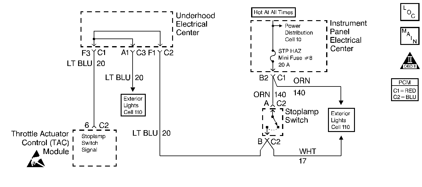
Circuit Description
The Brake Lamp Switch is a normally open switch. When the Brake Lamp Switch is closed, the TAC senses ignition voltage on the Brake Lamp Switch signal circuit.
If the TAC senses a voltage on the Brake Lamp Switch signal circuit when the Brake Lamp Switch should be open, this DTC sets.
Conditions for Running the DTC
| • | Engine speed is greater than 700 RPM. |
| • | Engine operates longer than 2.0 second. |
| • | Wheel speed must be greater than 30 MPH in order to enable the diagnostic. The diagnostic will disable when the wheel speed is below 10 MPH. |
| • | Vehicle speed is decreasing at a rate greater than 10.4 MPH over a one second period. |
Conditions for Setting the DTC
| • | The TAC does not detect voltage on the Brake Lamp Switch circuit when the Brake Lamp Switch should be closed. |
| • | The above conditions present for 1.5 seconds. |
Action Taken When the DTC Sets
| • | The powertrain control module (PCM) stores the DTC information into memory when the diagnostic runs and fails. |
| • | The malfunction indicator lamp (MIL) will not illuminate. |
| • | The PCM records the operating conditions at the time the diagnostic fails. The PCM stores this information in the Failure Records. |
Conditions for Clearing the MIL/DTC
| • | A last test failed, or the current DTC, clears when the diagnostic runs and does not fail. |
| • | A history DTC clears after 40 consecutive warm-up cycles, if failures are not reported by this or any other emission related diagnostic. |
| • | Use a scan tool in order to clear the MIL/DTC. |
Diagnostic Aids
Important:
• Remove any debris from the PCM\TAC module connector surfaces before
servicing the PCM\TAC module. Inspect the PCM\TAC module connector gaskets
when diagnosing/replacing the modules. Ensure that the gaskets are installed
correctly. The gaskets prevent water intrusion into the PCM\TAC modules. • Test drive the vehicle if you can not find a problem with the
switch or the circuit. An intermittent condition may be duplicated on a test
drive.
In order to adjust the Brake Lamp Switch perform the following:
- With the brake pedal depressed, insert the Brake Lamp Switch into the retainer until the switch body seats in the retainer. You can hear clicks as you push the threaded portion of the switch through the retainer.
- Slowly pull the brake pedal fully rearward against the stop until you can no longer hear the clicks.
Test Description
The numbers below refer to the step numbers on the diagnostic table.
-
This step determines if the fault is present.
-
This step verifies that the B+ feed is present at the Stop Lamp switch.
-
Check for a short to ground between the fuse and the Stop Lamp switch and between the Stop Lamp switch and the TAC module.
-
This DTC will not report a pass. The scan tool status for this DTC will never report a pass. The scan tool will only display when the diagnostic fails. The repair is not complete if the scan tool indicates that the diagnostic ran and failed.
Step | Action | Value(s) | Yes | No |
|---|---|---|---|---|
1 | Did you perform the Powertrain On-Board Diagnostic (OBD) System Check? | -- | ||
2 |
Does the display indicate Released? | -- | ||
3 | Depress the brake pedal approximately half-way. Does the display indicate Applied? | -- | Go to Diagnostic Aids | |
4 |
Is the test lamp illuminated? | -- | ||
5 |
Does the scan tool display Applied? | -- | ||
6 | Check the condition of the Stop Lamp fuse. Is the fuse open? | -- | ||
7 |
Does the display indicate Released? | -- | ||
8 | Check the adjustment of the Stop Lamp switch. Refer to Diagnostic Aids . Was an adjustment necessary? | -- | ||
9 |
Did you find and correct the condition? | -- | ||
10 |
Did you find and correct the condition? | -- | ||
Repair the short to ground in the Stop Lamp circuit. Is the action complete? | -- | -- | ||
12 | Repair the open between the Stop Lamp fuse and the Stop Lamp switch. Is the action complete? | -- | -- | |
13 | Replace the Stop Lamp switch. Is the action complete? | -- | -- | |
14 | Replace the TAC module. Refer to Powertrain Control Module/Throttle Actuator Control Module Replacement Is the action complete? | -- | -- | |
Does the scan tool indicate that this test failed? | -- | |||
16 | Select the Capture Info option and the Review Info option using the scan tool. Are any DTCs displayed that you have not diagnosed? | -- | Go to applicable DTC table | System OK |
