Removal Procedure
- Remove the intake manifold. Refer to Intake Manifold Replacement .
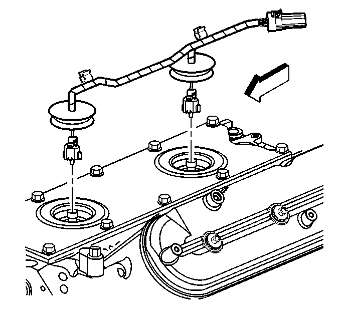
- Gently pry up the rubber grommets.
- Disconnect the knock sensor wire harness electrical connectors.
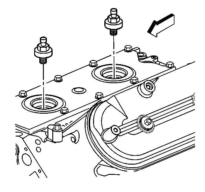
- Remove the knock sensors.
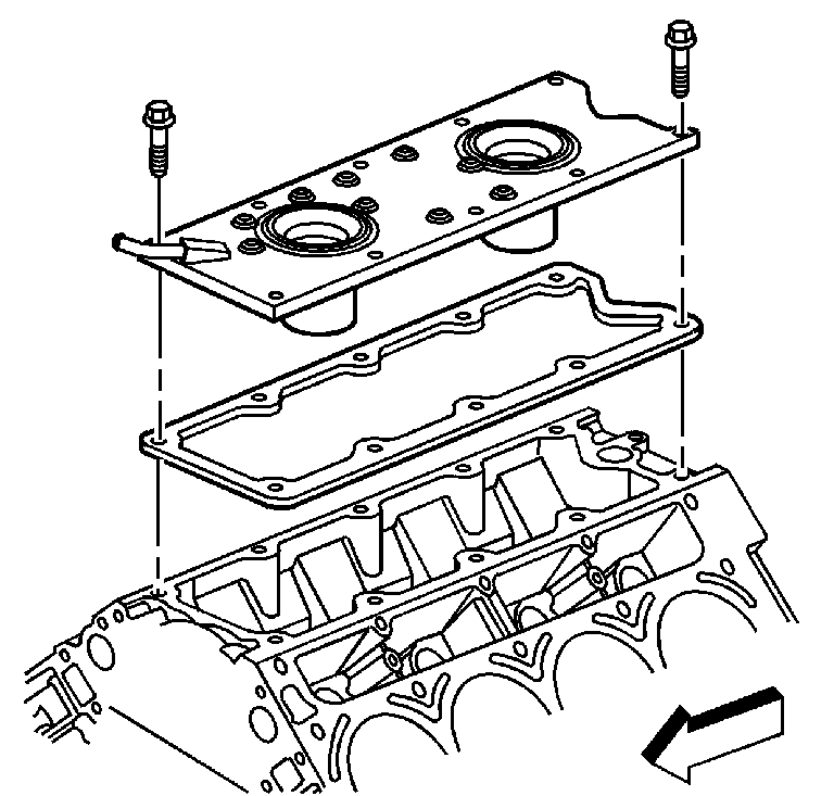
- if equipped with the 5.7 L, regular production option (RPO) LS1 engine, remove the engine valley cover bolts.
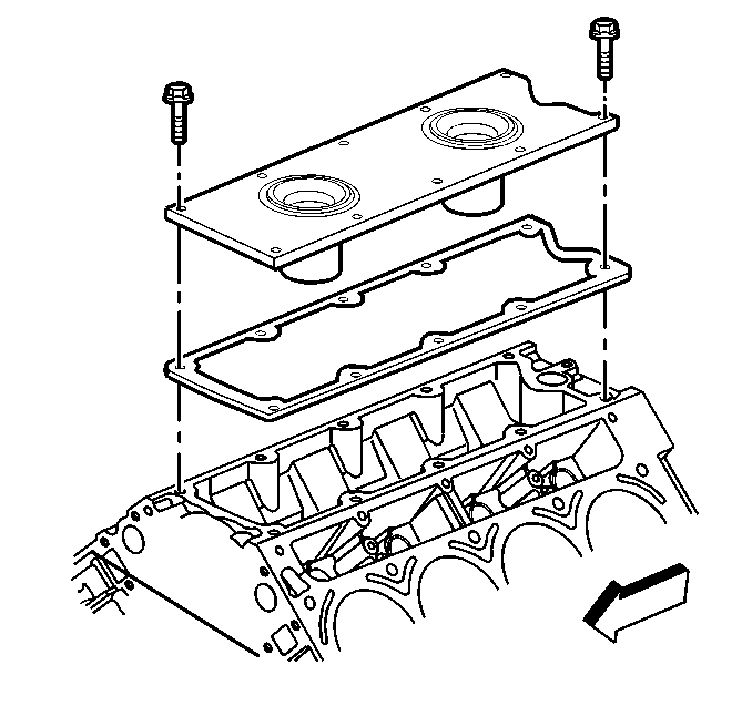
- If equipped with the 5.7 L, RPO LS6 engine, remove the engine valley cover bolts.
- Remove the engine valley cover and gasket.
- Discard the engine valley cover gasket.
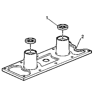
- Remove the knock sensor oil seals (1) from the cover (2).
- Clean and inspect the engine valley cover. Refer to Engine Block Valley Cover Cleaning and Inspection in Engine Mechanical-5.7L Unit Repair.
Installation Procedure
Important: All gasket surfaces should be free of oil or other foreign material during assembly.
- Install NEW knock sensor oil seals (1) into the valley cover (2).
- If equipped with the 5.7 L, RPO LS6 engine, install the engine valley cover and a NEW gasket.
- If equipped with the 5.7 L, RPO LS1 engine, install the engine valley cover and NEW gasket.
- Install the engine valley cover bolts.
- Install the knock sensors.
- Connect the knock sensor wire harness electrical connectors.
- Install the rubber grommets into the valley cover.
- Install the intake manifold. Refer to Intake Manifold Replacement .

Lubricate the seal surfaces with clean engine oil.


Notice: Use the correct fastener in the correct location. Replacement fasteners must be the correct part number for that application. Fasteners requiring replacement or fasteners requiring the use of thread locking compound or sealant are identified in the service procedure. Do not use paints, lubricants, or corrosion inhibitors on fasteners or fastener joint surfaces unless specified. These coatings affect fastener torque and joint clamping force and may damage the fastener. Use the correct tightening sequence and specifications when installing fasteners in order to avoid damage to parts and systems.
Tighten
Tighten the engine valley cover bolts to 25 N·m (18 lb ft).

Tighten
Tighten the knock sensors to 20 N·m (15 lb ft).

