Removal Procedure
Caution: In order to avoid being burned, do not service the exhaust system while it is still hot. Service the system when it is cool.
Caution: Always wear protective goggles and gloves when removing exhaust parts as falling rust and sharp edges from worn exhaust components could result in serious personal injury.
- Raise and suitably support the vehicle. Refer to Lifting and Jacking the Vehicle in General Information.
- Remove the connector position assurance (CPA) locks.
- Disconnect the oxygen sensor electrical connectors.
- Remove the oxygen sensor clips to the heat shields.
- Remove the oxygen sensors.
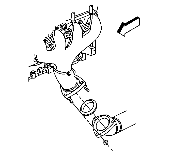
- Remove the exhaust manifold nuts.
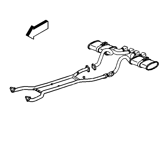
- Install adjustable jack stands under the front and rear of the catalytic converter.
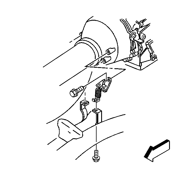
- Remove the exhaust pipe hanger lower bolts.
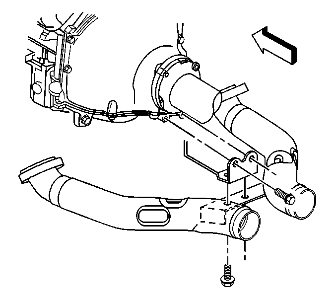
- Remove the exhaust pipe brace lower bolts.
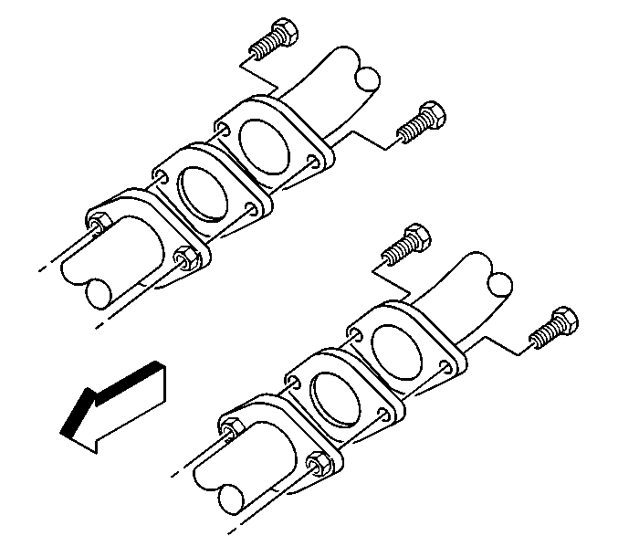
- Remove the exhaust muffler bolts.
- Remove the exhaust muffler gaskets.
- Lower the jack stands.
- With the aid of an assistant remove the catalytic converter from the jack stands.
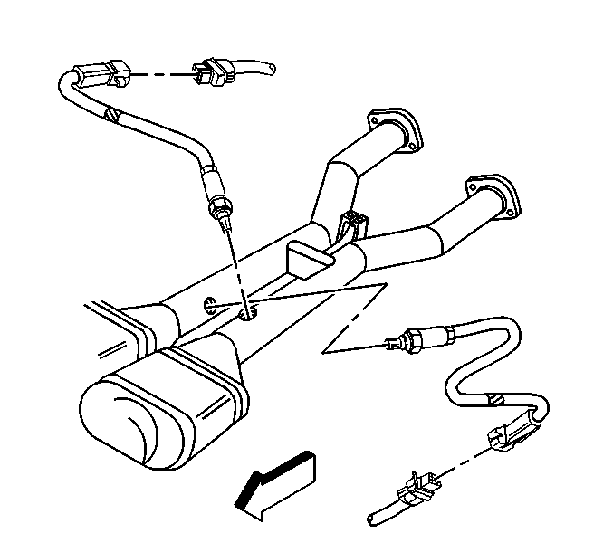
Notice: Handle the oxygen sensors carefully in order to prevent damage to the component. Keep the electrical connector and the exhaust inlet end free of contaminants. Do not use cleaning solvents on the sensor. Do not drop or mishandle the sensor.
Installation Procedure
Notice: When inspecting or replacing exhaust system components, make sure there is adequate clearance from all points on the underbody to prevent overheating of the floor pan and possible damage to the passenger compartment insulation and trim materials.
- With the aid of an assistant install the catalytic converter to the jack stands.
- Raise the jack stands in order to position the catalytic converter.
- Install NEW exhaust muffler gaskets.
- Install ALL exhaust bolts until snug to ensure correct alignment of the catalytic converter.
- Remove the adjustable jack stands.
- Tighten the exhaust muffler bolts in the following sequence:
- Tighten the exhaust manifold nuts.
- Tighten the exhaust pipe brace lower bolts.
- Tighten the exhaust pipe hanger lower bolts.
- Apply anti-sieze compound GM P/N 12377953 or equivalent to the threads of the oxygen sensor.
- Install the oxygen sensors.
- Install the oxygen sensor clips to the heat shields.
- Connect the oxygen sensor electrical connectors.
- Install the CPA locks.
- Lower the vehicle.


Notice: Use the correct fastener in the correct location. Replacement fasteners must be the correct part number for that application. Fasteners requiring replacement or fasteners requiring the use of thread locking compound or sealant are identified in the service procedure. Do not use paints, lubricants, or corrosion inhibitors on fasteners or fastener joint surfaces unless specified. These coatings affect fastener torque and joint clamping force and may damage the fastener. Use the correct tightening sequence and specifications when installing fasteners in order to avoid damage to parts and systems.
| 6.1. | Left inboard |
| 6.2. | Left outboard |
| 6.3. | Right inboard |
| 6.4. | Right outboard |
Tighten
Tighten the exhaust muffler bolts to 50 N·m (37 lb ft).

Tighten
Tighten the exhaust manifold nuts to 20 N·m (15 lb ft).

Tighten
Tighten the exhaust pipe brace bolts to 50 N·m (37 lb ft).

Tighten
Tighten the exhaust pipe hanger bolts to 50 N·m (37 lb ft).

Notice: Handle the oxygen sensors carefully in order to prevent damage to the component. Keep the electrical connector and the exhaust inlet end free of contaminants. Do not use cleaning solvents on the sensor. Do not drop or mishandle the sensor.
Tighten
Tighten the oxygen sensors to 42 N·m (30 lb ft).
