Piston, Pin, and Piston Rings
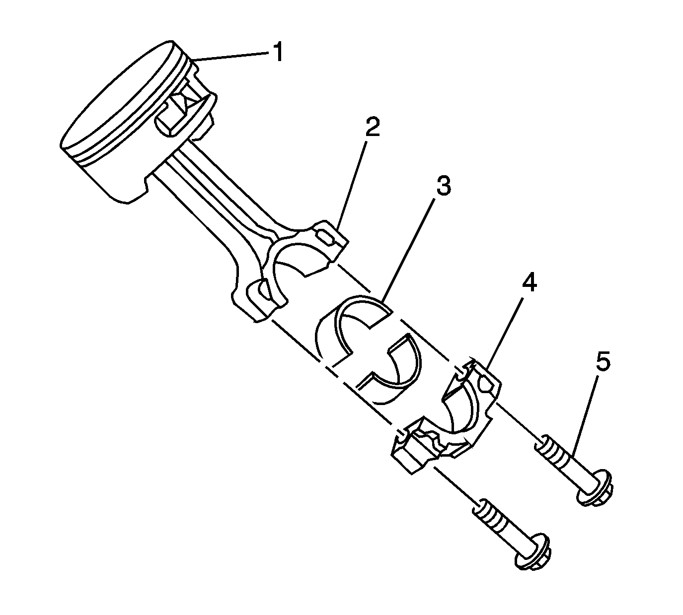
Important:
| • | Replace pistons, pins, and connecting rods that are damaged or show signs
of excessive wear. |
| • | The piston, pin, and connecting rod are to be serviced as an assembly. |
| • | Do not wire brush any part of the piston. |
| • | Measurement of the components should be taken with the components at normal
room temperature. |
- Clean the varnish and carbon from the piston (1) using cleaning solvent.
Caution: Wear safety glasses in order to avoid eye damage.
- Dry the components with compressed air.
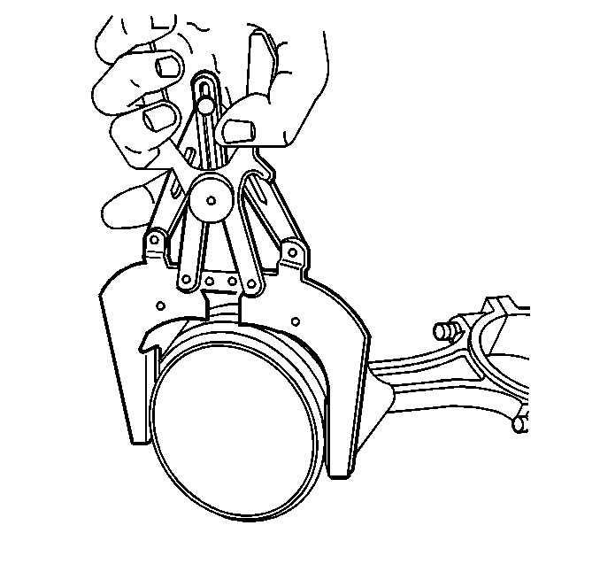
- Clean
the piston ring grooves with a suitable ring groove cleaning tool.
- Clean the oil lubrication holes and slots.
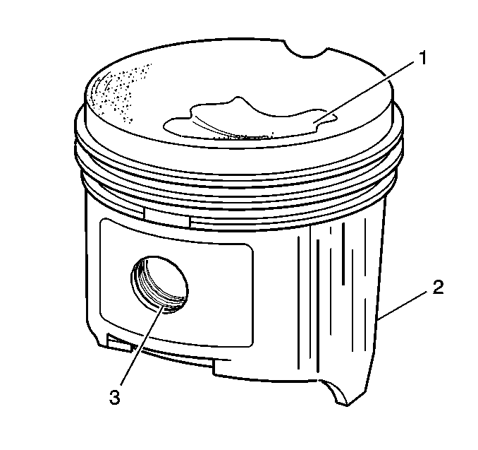
- Inspect the piston for the following conditions:
| • | Cracks in the piston ring lands, the piston skirt, or pin bosses |
| • | Piston ring grooves for nicks, burrs, or warpage which may cause the piston
ring to bind |
| • | MINOR imperfections may be removed from the piston with a
fine file. |
| • | Scuffed or damaged skirts (2) |
| • | Eroded areas at the top of the piston (1) |
| • | Scoring to the full-floating design piston pin bore (3)
or piston pin |
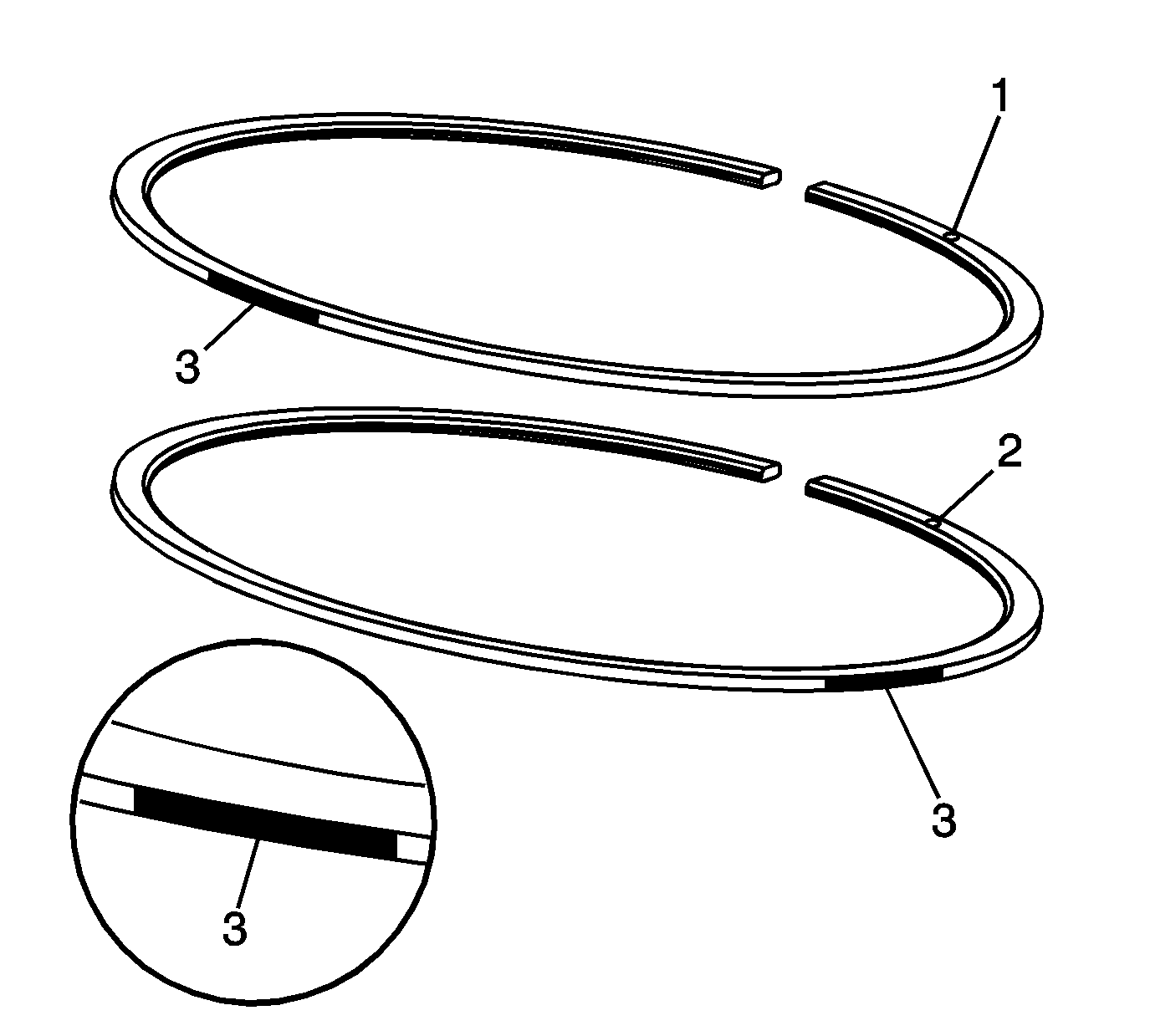
- Identify the NEW upper and lower compression rings. The upper compression ring
can be identified by a paint mark (3) located 180 degrees from the end
gap. The lower compression ring can be identified by a paint mark (3) located
90 degrees from the end gap. Both rings should be installed with the orientation
marks (1, 2) facing the top of the piston.
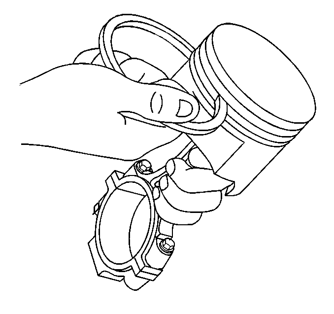
- Insert the edge of the piston
ring into the piston ring groove.
Roll the piston ring completely around
the piston. If binding is caused by distorted ring groove, MINOR imperfections may
be removed with a fine file. If binding is caused by a distorted piston ring, replace
the rings as required.
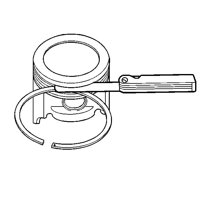
- Measure
the piston ring side clearance with a feeler gauge. If side clearance is not within
specifications, try another piston ring. If the proper ring-to- groove
clearance cannot be obtained, replace the piston, pin, and connecting rod assembly.
Refer to
Engine Mechanical Specifications
.
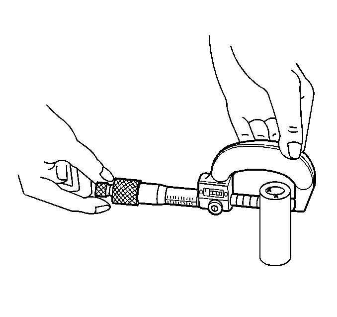
- To
determine piston pin-to-bore clearance, use a micrometer and measure
the piston pin outside diameter (OD).
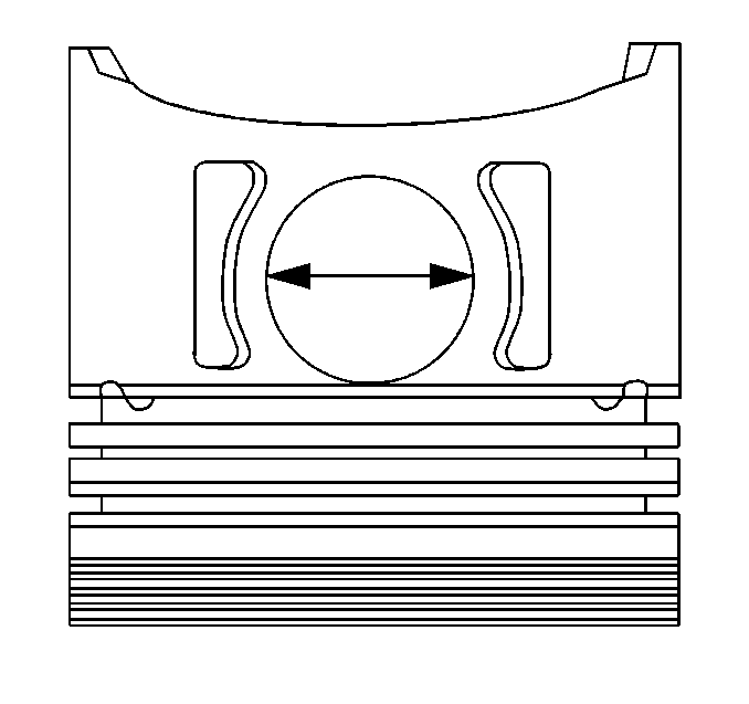
- To determine the piston pin-to-bore
clearance, use an inside micrometer and measure the piston pin bore inside diameter (ID).
- Subtract the piston pin OD measurement from the piston pin bore ID measurement
to determine pin-to-bore clearance.
Refer to
Engine Mechanical Specifications
.
Measuring Piston Ring End Gap

Important:
| • | Do not attempt to file the end of the piston ring to achieve the proper
end gap clearance. |
| • | Measure the piston ring in the cylinder in which it will be used. |
- Identify the NEW upper and lower compression rings. The upper compression ring
can be identified by a paint mark (3) located 180 degrees from the end
gap. The lower compression ring can be identified by a paint mark (3) located
90 degrees from the end gap. Both rings should be installed with the orientation
marks (1, 2) facing the top of the piston.
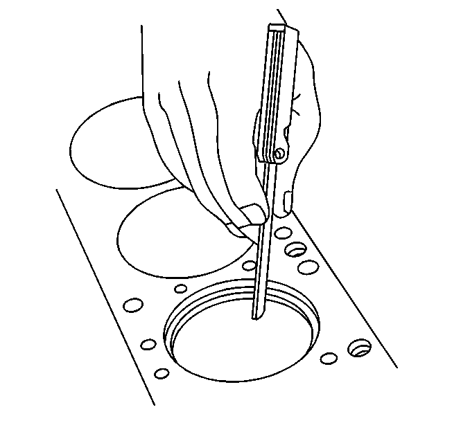
- Place
the piston ring into the cylinder bore 6.5 mm (0.25 in) below the top
of the ring travel area.
- Insert a feeler gage and measure the piston ring end gap. Refer to
Engine Mechanical Specifications
.
Connecting Rod and Bearings

Important:
| • | The powdered metal connecting rod and cap are machined for proper clearances.
The connecting rod and cap must be used as an assembly with no repair or modifications
to either mating surface. Do not attempt to repair the rod or cap. If service is required,
replace the piston and pin as an assembly. |
| • | Do not attempt to repair the bolt hole threads of the connecting rod. |
- Clean the connecting rod (2) and cap (4) in solvent.
Caution: Wear safety glasses in order to avoid eye damage.
- Dry the components with compressed air.
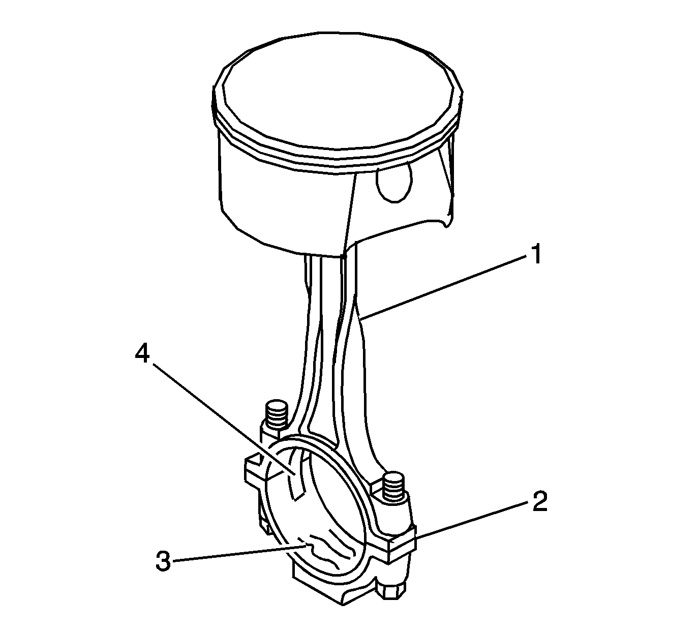
- Inspect the connecting rod for the following
conditions:
| • | Proper fit of the connecting rod and cap mating surfaces (2) |
| • | Nicks or gouges in the bearing bore (3) |
| • | Damage to the bearing locating slots (4) |
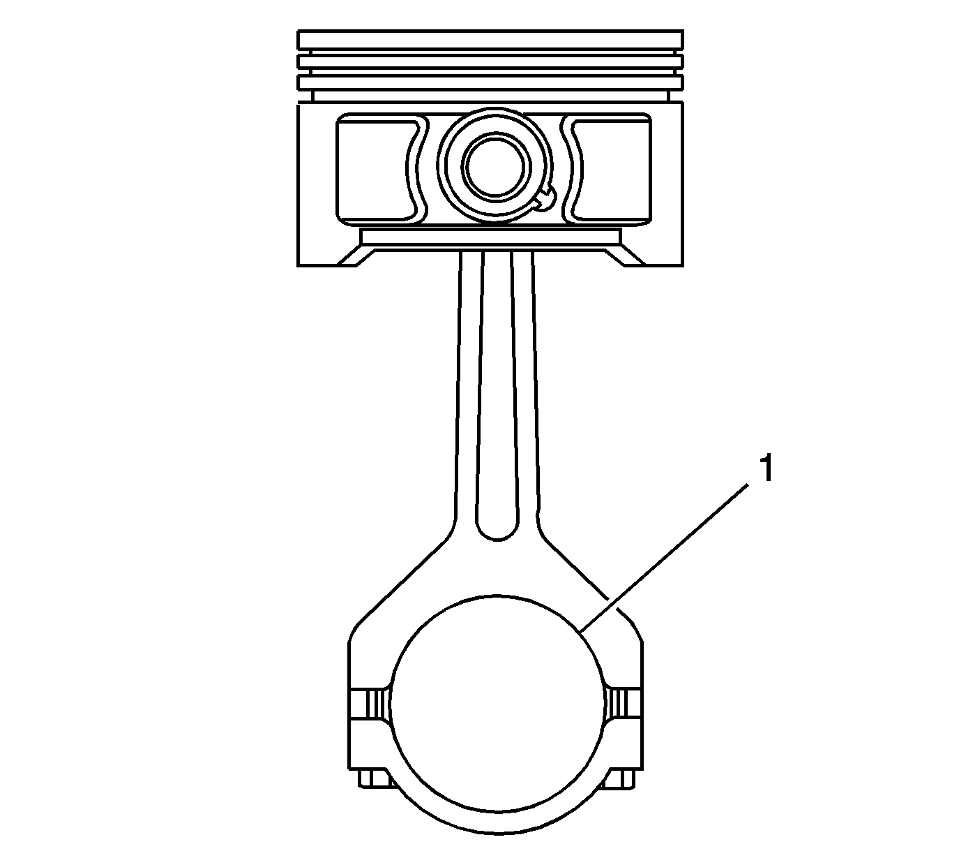
- Measure the connecting rod bearing bore (1)
for an out-of-round condition. Refer to
Engine Mechanical Specifications
.

- To
determine piston pin-to-connecting rod bore clearance, use a micrometer
and measure the piston pin outside diameter (OD).
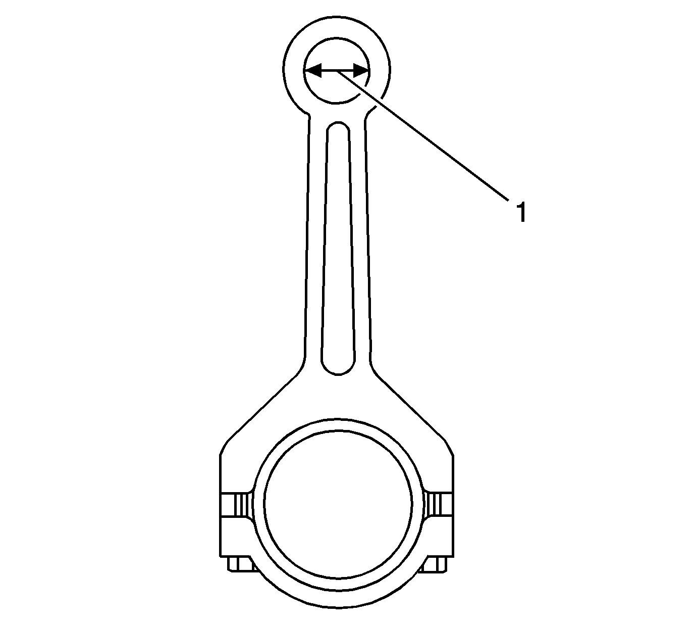
- To determine piston pin-to-connecting
rod bore clearance, use a micrometer and measure the connecting rod pin bore (1)
inside diameter (ID).
- Subtract the piston pin OD measurement from the connecting rod pin bore
ID measurement to determine pin-to-bore clearance. Refer to
Engine Mechanical Specifications
.
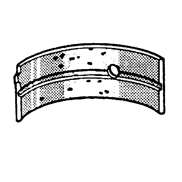
- Inspect
the connecting rod bearings for craters or pockets. Flattened sections on the bearing
halves indicate fatigue.
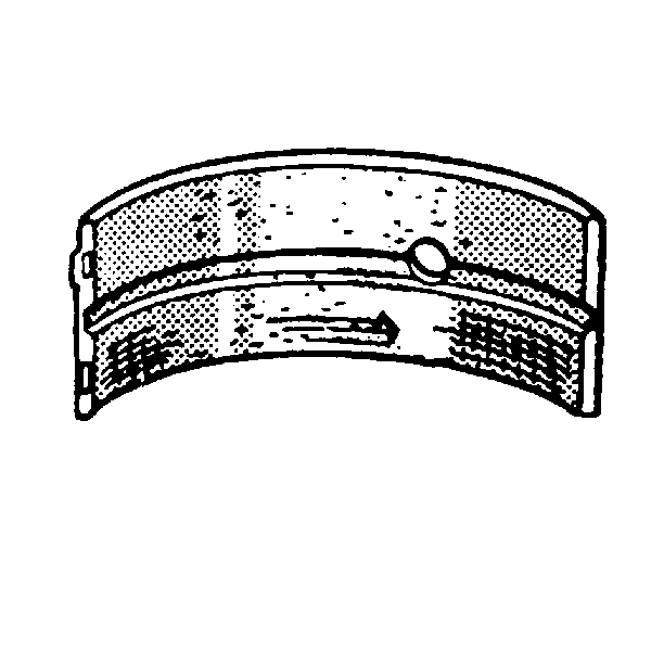
- Inspect
the connecting rod bearings for excessive scoring or discoloration.
- Inspect the connecting rod bearings for dirt or debris imbedded into the
bearing material.
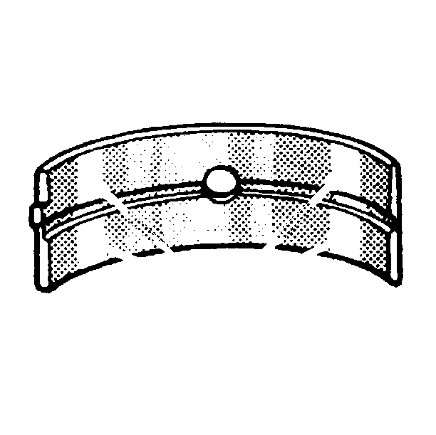
- Inspect
the connecting rod bearings for improper seating indicated by bright, polished sections
of the bearing surface.


