|
| ||||||||||||||
|---|---|---|---|---|---|---|---|---|---|---|---|---|---|---|---|
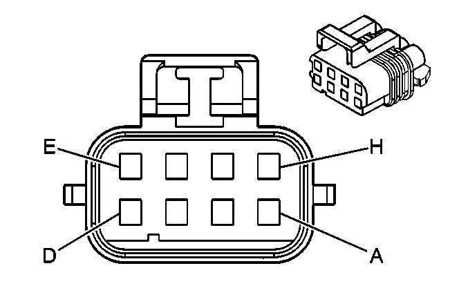
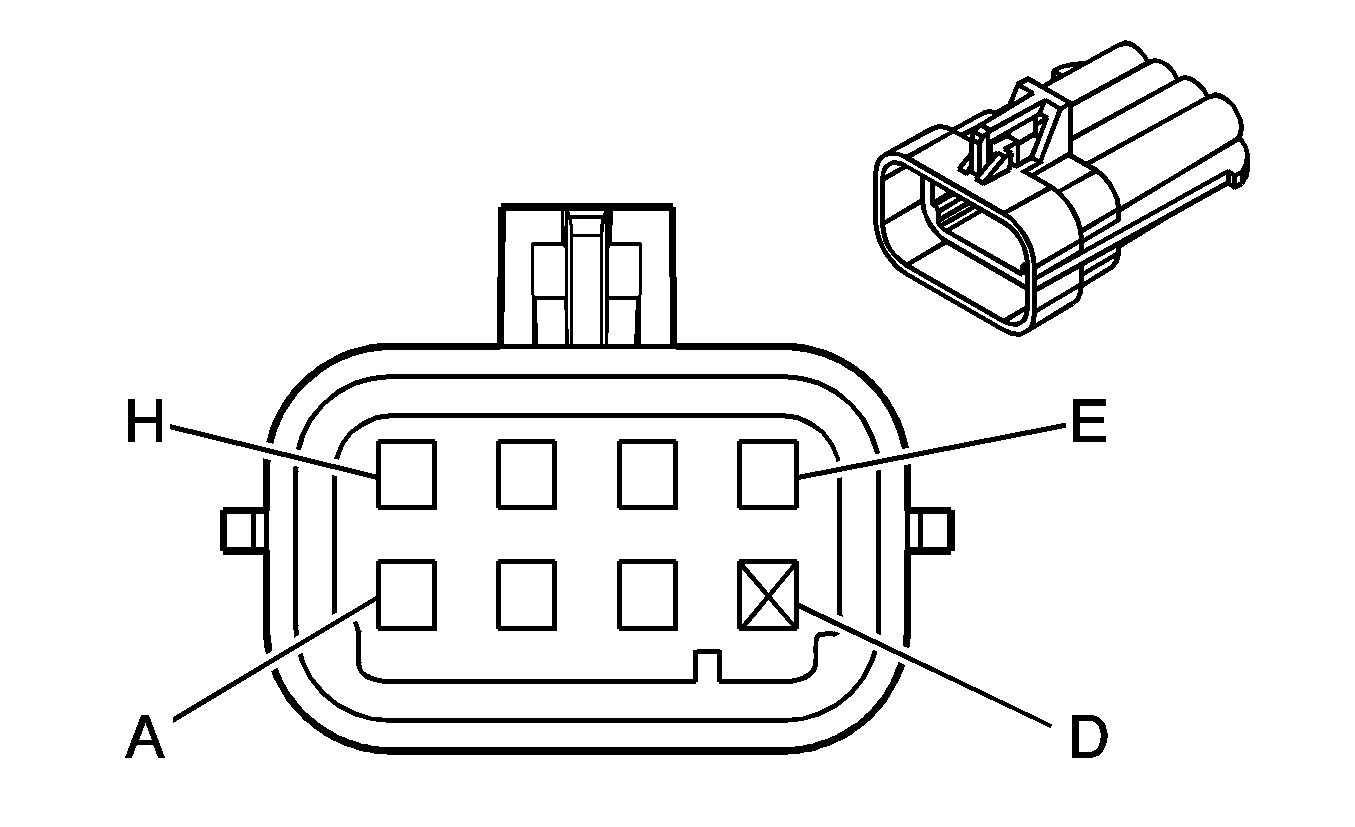
Connector Part Information |
| Connector Part Information |
| ||||||||||||
Pin | Wire Color | Circuit No. | Function | Pin | Wire Color | Circuit No. | Function | ||||||||
A | BRN | 9 | Park Lamp Supply Voltage | A | BRN | 9 | Park Lamp Supply Voltage | ||||||||
B | BRN | 9 | Park Lamp Supply Voltage | B | BRN | 9 | Park Lamp Supply Voltage | ||||||||
C | BRN | 9 | Park Lamp Supply Voltage | C | BRN | 9 | Park Lamp Supply Voltage | ||||||||
D | BRN | 9 | Park Lamp Supply Voltage | D | BRN | 9 | Park Lamp Supply Voltage | ||||||||
E | LT BLU/ WHT | 1314 | Left Front Turn Signal Lamp Supply Voltage | E | LT BLU/ WHT | 1314 | Left Front Turn Signal Lamp Supply Voltage | ||||||||
F | DK BLU/ WHT | 1315 | Right Front Turn Signal Lamp Supply Voltage | F | DK BLU/ WHT | 1315 | Right Front Turn Signal Lamp Supply Voltage | ||||||||
G | BLK | 150 | Ground | G | BLK | 150 | Ground | ||||||||
H | -- | -- | Not Used | H | -- | -- | Not Used | ||||||||
|
| ||||||||||||||
|---|---|---|---|---|---|---|---|---|---|---|---|---|---|---|---|
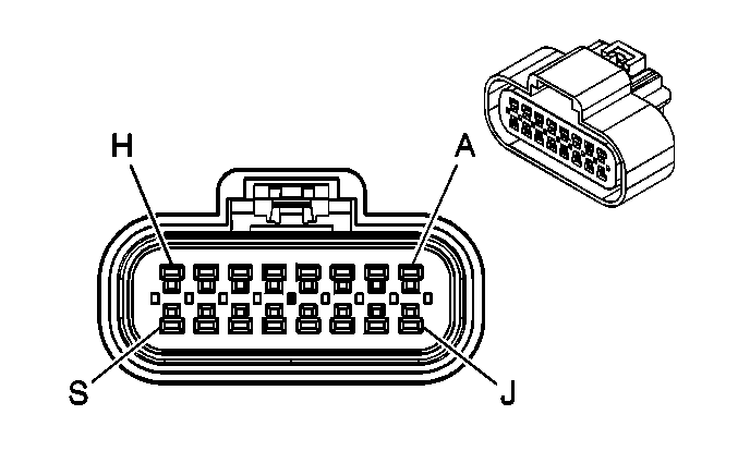
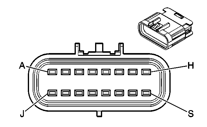
Connector Part Information |
| Connector Part Information |
| ||||||||||||
Pin | Wire Color | Circuit No. | Function | Pin | Wire Color | Circuit No. | Function | ||||||||
A | LT BLU | 1764 | Steering Wheel Position Signal B | A | LT BLU | 1764 | Steering Wheel Position Signal B | ||||||||
B | DK GRN /WHT | 817 | Vehicle Speed Signal | B | DK GRN /WHT | 817 | Vehicle Speed Signal | ||||||||
C | DK GRN | 1049 | PCM Class 2 Serial Data | C | DK GRN | 1049 | PCM Class 2 Serial Data | ||||||||
D | DK GRN /WHT | 762 | A/C Request Signal | D | DK GRN /WHT | 762 | A/C Request Signal | ||||||||
E | GRY | 48 | Cruise Control Release Switch Signal | E | GRY | 48 | Cruise Control Release Switch Signal | ||||||||
F | LT GRN /BLK | 735 | Ambient Temperature Sensor Signal | F | LT GRN /BLK | 735 | Ambient Temperature Sensor Signal | ||||||||
G | GRY/BLK | 1798 | Ground | G | GRY/BLK | 1798 | Ground | ||||||||
H | LT GRN | 1763 | Steering Wheel Position Signal A | H | LT GRN | 1763 | Steering Wheel Position Signal A | ||||||||
J | BLK | 470 | Low Reference | J | BLK | 470 | Low Reference | ||||||||
K | GRY | 1056 | Steering Wheel Position Sensor 5V Reference Voltage | K | GRY | 1056 | Steering Wheel Position Sensor 5V Reference Voltage | ||||||||
L | ORN/BLK | 556 | Low Reference | L | ORN/BLK | 556 | Low Reference | ||||||||
M | LT BLU | 1122 | ABS/TCS Class 2 Serial Data | M | LT BLU | 1122 | ABS/TCS Class 2 Serial Data | ||||||||
N | DK BLU | 716 | Yaw Rate Sensor Signal | N | DK BLU | 716 | Yaw Rate Sensor Signal | ||||||||
P | LT GRN /BLK | 1338 | Lateral Accelerometer Signal | P | LT GRN /BLK | 1338 | Lateral Accelerometer Signal | ||||||||
R | GRY | 847 | Extended Travel Brake Switch Signal | R | GRY | 847 | Extended Travel Brake Switch Signal | ||||||||
S | DK GRN /WHT | 357 | Oil Temperature Sensor Signal | S | DK GRN /WHT | 357 | Oil Temperature Sensor Signal | ||||||||
|
| ||||||||||||||
|---|---|---|---|---|---|---|---|---|---|---|---|---|---|---|---|
Connector Part Information |
| Connector Part Information |
| ||||||||||||
Pin | Wire Color | Circuit No. | Function | Pin | Wire Color | Circuit No. | Function | ||||||||
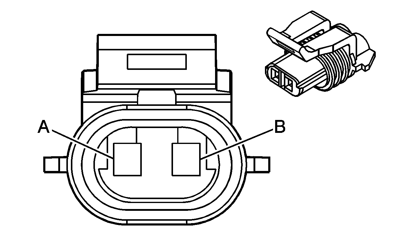
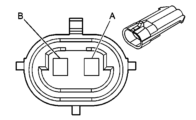
A | LT BLU | 830 | Left Front Wheel Speed Sensor Signal | A | BLK | 830 | Left Front Wheel Speed Sensor Signal | ||||||||
B | YEL | 873 | Left Front Wheel Speed Sensor Low Reference | B | WHT | 873 | Left Front Wheel Speed Sensor Low Reference | ||||||||

|

| ||||||||||||||
|---|---|---|---|---|---|---|---|---|---|---|---|---|---|---|---|
Connector Part Information |
| Connector Part Information |
| ||||||||||||
Pin | Wire Color | Circuit No. | Function | Pin | Wire Color | Circuit No. | Function | ||||||||
A | DK GRN | 872 | Right Front Wheel Speed Sensor Signal | A | WHT | 872 | Right Front Wheel Speed Sensor Signal | ||||||||
B | TAN | 833 | Right Front Wheel Speed Sensor Low Reference | B | BLK | 833 | Right Front Wheel Speed Sensor Low Reference | ||||||||

| |||||||||||||||
|---|---|---|---|---|---|---|---|---|---|---|---|---|---|---|---|
Connector Part Information |
| Connector Part Information |
| ||||||||||||
Pin | Wire Color | Circuit No. | Function | Pin | Wire Color | Circuit No. | Function | ||||||||
A | BLK/WHT | 151 | Ground | A | BLK | 151 | Ground | ||||||||
B | RED | 2127 | IC 7 Control | B | RED | 2127 | IC 7 Control | ||||||||
C | DK GRN | 2125 | IC 5 Control | C | DK GRN | 2125 | IC 5 Control | ||||||||
D | -- | -- | Not Used | D | -- | -- | Not Used | ||||||||
E | BRN | 2129 | Low Reference | E | BRN | 2129 | Low Reference | ||||||||
F | LT BLU | 2123 | IC 3 Control | F | LT BLU | 2123 | IC 3 Control | ||||||||
G | PPL | 2121 | IC 1 Control | G | PPL | 2121 | IC 1 Control | ||||||||
H | PNK | 639 | Ignition 1 Voltage | H | PNK | 39 | Ignition 1 Voltage | ||||||||

| |||||||||||||||
|---|---|---|---|---|---|---|---|---|---|---|---|---|---|---|---|
Connector Part Information |
| Connector Part Information |
| ||||||||||||
Pin | Wire Color | Circuit No. | Function | Pin | Wire Color | Circuit No. | Function | ||||||||
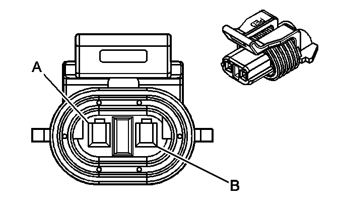
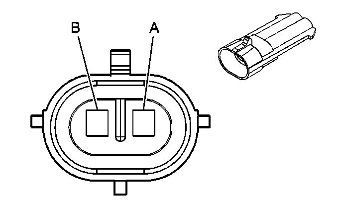
A | BLK/WHT | 151 | Ground | A | BLK | 151 | Ground | ||||||||
B | RED/WHT | 2122 | IC 2 Control | B | RED | 2127 | IC 2 Control | ||||||||
C | DK GRN /WHT | 2124 | IC 4 Control | C | DK GRN | 2125 | IC 4 Contr | ||||||||
D | -- | -- | Not Used | D | -- | -- | Not Used | ||||||||
E | BRN/WHT | 2130 | Low Reference | E | BRN | 2129 | Low Reference | ||||||||
F | LT BLU /WHT | 2126 | IC 6 Control | F | LT BLU | 2123 | IC 6 Control | ||||||||
G | PPL/WHT | 2128 | IC 8 Control | G | PPL | 2121 | IC 8 Control | ||||||||
H | PNK | 839 | Ignition 1 Voltage | H | PNK | 39 | Ignition 1 Voltage | ||||||||
|
| ||||||||||||||
|---|---|---|---|---|---|---|---|---|---|---|---|---|---|---|---|
Connector Part Information |
| Connector Part Information |
| ||||||||||||
Pin | Wire Color | Circuit No. | Function | Pin | Wire Color | Circuit No. | Function | ||||||||
A | DK BLU | 496 | Knock Sensor [1] Signal | A | DK BLU | 496 | Knock Sensor [1] Signal | ||||||||
B | LT BLU | 1876 | Knock Sensor 2 Signal | B | LT BLU | 1876 | Knock Sensor 2 Signal | ||||||||

|

| ||||||||||||||
|---|---|---|---|---|---|---|---|---|---|---|---|---|---|---|---|
Connector Part Information |
| Connector Part Information |
| ||||||||||||
Pin | Wire Color | Circuit No. | Function | Pin | Wire Color | Circuit No. | Function | ||||||||
A | BLK | 40 | Battery Positive Voltage | A | ORN | 40 | Battery Positive Voltage | ||||||||
B | BLK | 150 | Ground | B | BLK | 150 | Ground | ||||||||
|
| ||||||||||||||
|---|---|---|---|---|---|---|---|---|---|---|---|---|---|---|---|
Connector Part Information |
| Connector Part Information |
| ||||||||||||
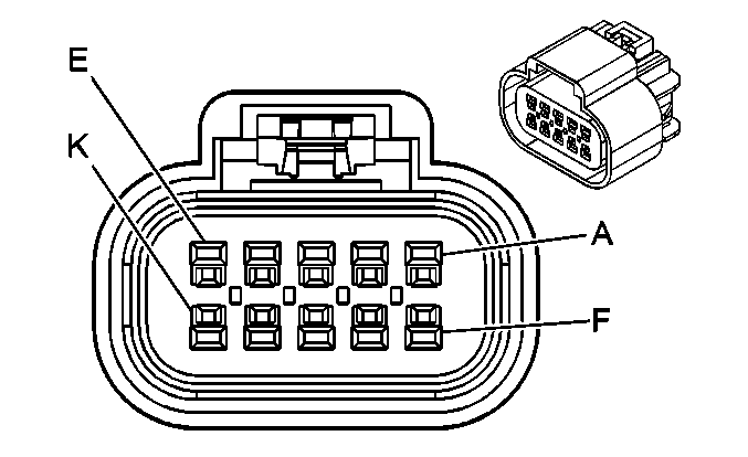
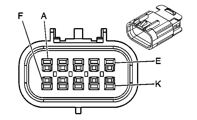
Pin | Wire Color | Circuit No. | Function | Pin | Wire Color | Circuit No. | Function | ||||||||
A | BRN | 9 | Park Lamp Supply Voltage | A | BRN | 9 | Park Lamp Supply Voltage | ||||||||
B | LT GRN | 24 | Backup Lamp Supply Voltage | B | LT GRN | 24 | Backup Lamp Supply Voltage | ||||||||
C | GRY | 120 | Fuel Pump Supply Voltage | C | GRY | 120 | Fuel Pump Supply Voltage | ||||||||
D | BRN | 641 | Ignition 3 Voltage | D | BRN | 641 | Ignition 3 Voltage | ||||||||
E | PNK | 339 | Ignition 1 Voltage | E | PNK | 339 | Ignition 1 Voltage | ||||||||
F | LT BLU | 820 | CHMSL Supply Voltage | F | YEL | 820 | CHMSL Supply Voltage | ||||||||
G | GRY | 1524 | Backup Lamp Supply Voltage | G | GRY | 1524 | Backup Lamp Supply Voltage | ||||||||
H | RED | 122 | Rear Fog Lamp Supply Voltage (Europe) | H | RED | 122 | Rear Fog Lamp Supply Voltage (Europe) | ||||||||
J-K | -- | -- | Not Used | J -K | -- | -- | Not Used | ||||||||
|
| ||||||||||||||
|---|---|---|---|---|---|---|---|---|---|---|---|---|---|---|---|
Connector Part Information |
| Connector Part Information |
| ||||||||||||
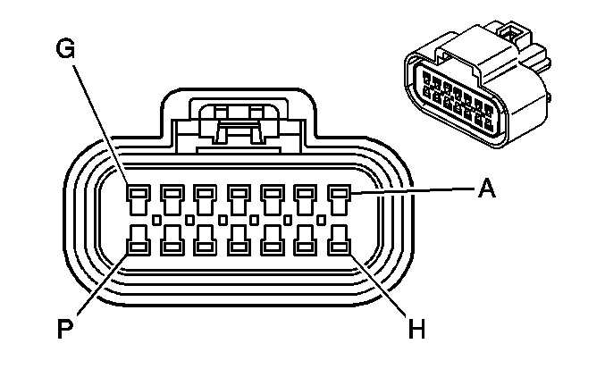
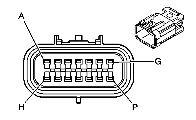
Pin | Wire Color | Circuit No. | Function | Pin | Wire Color | Circuit No. | Function | ||||||||
A | BRN | 9 | Park Lamp Supply Voltage | A | BRN | 9 | Park Lamp Supply Voltage | ||||||||
B | LT GRN | 24 | Backup Lamp Supply Voltage | B | LT GRN | 24 | Backup Lamp Supply Voltage | ||||||||
C | GRY | 120 | Fuel Pump Supply Voltage | C | GRY | 120 | Fuel Pump Supply Voltage | ||||||||
D | BRN | 641 | Ignition 3 Voltage | D | BRN | 641 | Ignition 3 Voltage | ||||||||
E | PNK | 339 | Ignition 1 Voltage | E | PNK | 339 | Ignition 1 Voltage | ||||||||
F | LT BLU | 820 | CHMSL Supply Voltage | F | YEL | 820 | CHMSL Supply Voltage | ||||||||
G | GRY | 1524 | Backup Lamp Supply Voltage | G | GRY | 1524 | Backup Lamp Supply Voltage | ||||||||
H | RED | 122 | Rear Fog Lamp Supply Voltage (Europe) | H | RED | 122 | Rear Fog Lamp Supply Voltage (Europe) | ||||||||
J -K | -- | -- | Not Used | J- K | -- | Not Used | |||||||||
L | LT BLU/WHT | 1116 | Right Front Suspension Damper Solenoid Control | L | LT BLU | 1116 | Right Front Suspension Damper Solenoid Control | ||||||||
M | GRY | 1117 | Right Front Suspension Damper Solenoid Low Reference | M | GRY | 1117 | Right Front Suspension Damper Solenoid Low Reference | ||||||||
N | LT BLU/WHT | 1107 | Left Front Suspension Damper Solenoid Control | N | LT BLU | 1107 | Left Front Suspension Damper Solenoid Control | ||||||||
P | GRY | 1113 | Left Front Suspension Damper Solenoid Low Reference | P | GRY | 1113 | Left Front Suspension Damper Solenoid Low Reference | ||||||||

| |||||||||||||||
|---|---|---|---|---|---|---|---|---|---|---|---|---|---|---|---|
Connector Part Information |
| Connector Part Information |
| ||||||||||||
Pin | Wire Color | Circuit No. | Function | Pin | Wire Color | Circuit No. | Function | ||||||||
A | GRY | 587 | Skip/Shift Solenoid Control | A | GRY | 587 | Skip/Shift Solenoid Control | ||||||||
B | YEL | 400 | Signal High - Front | B | YEL | 400 | Signal High - Front | ||||||||
C | PPL | 401 | Signal Low - Front | C | PPL | 401 | Signal Low - Front | ||||||||
D | YEL/BLK | 1227 | TFT Sensor Signal | D | YEL/BLK | 1227 | TFT Sensor Signal | ||||||||
E | DK GRN /WHT | 817 | Vehicle Speed Signal | E | DK GRN /WHT | 817 | Vehicle Speed Signal | ||||||||
F-K | -- | -- | Not Used | F-K | -- | -- | Not Used | ||||||||
L | DK GRN | 890 | Fuel Tank Pressure Sensor Signal | L | DK GRN | 890 | Fuel Tank Pressure Sensor Signal | ||||||||
M | LT BLU | 1937 | Fuel Level Sensor Signal-Secondary | M | LT BLU | 1937 | Fuel Level Sensor Signal-Secondary | ||||||||
N | PNK/WHT | 1101 | Damping Lift/Dive Signal | N | PNK/WHT | 1101 | Damping Lift/Dive Signal | ||||||||
P | WHT | 1310 | Left Rear Position Sensor Signal | P | WHT | 1310 | Left Rear Position Sensor Signal | ||||||||
R | GRY | 598 | 5 Volt Reference | R | GRY | 598 | 5 Volt Reference | ||||||||
S | GRY | 720 | Low Reference | S | GRY | 720 | Low Reference | ||||||||
T | LT GRN | 1652 | Reverse Lockout Solenoid Control | T | LT GRN | 1652 | Reverse Lockout Solenoid Control | ||||||||
U | DK BLU | 1936 | Fuel Level Sensor Signal-Primary | U | DK BLU | 1936 | Fuel Level Sensor Signal-Primary | ||||||||
V | ORN/BLK | 1057 | Low Reference (Europe) | V | ORN/BLK | 1057 | Low Reference (Europe) | ||||||||
W | -- | -- | Not Used | W | -- | -- | Not Used | ||||||||

| |||||||||||||||
|---|---|---|---|---|---|---|---|---|---|---|---|---|---|---|---|
Connector Part Information |
| Connector Part Information |
| ||||||||||||
Pin | Wire Color | Circuit No. | Function | Pin | Wire Color | Circuit No. | Function | ||||||||
A | ORN/BLK | 1057 | Low Reference | A | ORN/BLK | 1057 | Low Reference | ||||||||
B | LT GRN | 1222 | 1-2 Shift Solenoid Valve Control | B | LT GRN | 1222 | 1-2 Shift Solenoid Valve Control | ||||||||
C | YEL/BLK | 1223 | 2-3 Shift Solenoid Valve Control | C | YEL/BLK | 1223 | 2-3 Shift Solenoid Valve Control | ||||||||
D | PNK | 1224 | Transmission Fluid Pressure Switch Signal A | D | PNK | 1224 | Transmission Fluid Pressure Switch Signal A | ||||||||
E | DK BLU | 1225 | Transmission Fluid Pressure Switch Signal B | E | DK BLU | 1225 | Transmission Fluid Pressure Switch Signal B | ||||||||
F-J | -- | -- | Not Used | F-J | -- | -- | Not Used | ||||||||
K | WHT | 687 | 3-2 Shift Solenoid Valve Control | K | WHT | 687 | 3-2 Shift Solenoid Valve Control | ||||||||
L | RED | 1226 | Transmission Fluid Pressure Switch Signal C | L | RED | 1226 | Transmission Fluid Pressure Switch Signal C | ||||||||
M | YEL/BLK | 1227 | TFT Sensor Signal | M | YEL/BLK | 1227 | TFT Sensor Signal | ||||||||
N | RED/BLK | 1228 | PC Solenoid Valve High Control | N | RED/BLK | 1228 | PC Solenoid Valve High Control | ||||||||
P | LT BLU /WHT | 1229 | PC Solenoid Valve Low Control | P | LT BLU /WHT | 1229 | PC Solenoid Valve Low Control | ||||||||
R | BLK/WHT | 771 | Transmission Range Switch Signal A | R | BLK/WHT | 771 | Transmission Range Switch Signal A | ||||||||
S | YEL | 772 | Transmission Range Switch Signal B | S | YEL | 772 | Transmission Range Switch Signal B | ||||||||
T | GRY | 773 | Transmission Range Switch Signal C | T | GRY | 773 | Transmission Range Switch Signal C | ||||||||
U | WHT | 776 | Transmission Range Switch Signal P | U | WHT | 776 | Transmission Range Switch Signal P | ||||||||
V | BRN | 418 | TCC PWM Solenoid Valve Control | V | BRN | 418 | TCC PWM Solenoid Valve Control | ||||||||
W | TAN/BLK | 422 | TCC Solenoid Valve Control | W | TAN/BLK | 422 | TCC Solenoid Valve Control | ||||||||

|

| ||||||||||||||
|---|---|---|---|---|---|---|---|---|---|---|---|---|---|---|---|
Connector Part Information |
| Connector Part Information |
| ||||||||||||
Pin | Wire Color | Circuit No. | Function | Pin | Wire Color | Circuit No. | Function | ||||||||
A | YEL | 18 | Left Rear Stop/Turn Lamp Supply Voltage | A | YEL | 18 | Left Rear Stop/Turn Lamp Supply Voltage | ||||||||
B | DK GRN | 19 | Right Rear Stop/Turn Lamp Supply Voltage | B | DK GRN | 19 | Right Rear Stop/Turn Lamp Supply Voltage | ||||||||
C | YEL | 269 | Starter Enable Relay Coil Supply Voltage | C | YEL | 269 | Starter Enable Relay Coil Supply Voltage | ||||||||
D | PPL | 1606 | Crank Voltage | D | PPL | 1606 | Crank Voltage | ||||||||
E | BRN | 341 | Ignition 3 Voltage | E | BRN | 341 | Ignition 3 Voltage | ||||||||
F | ORN/BLK | 434 | Neutral Safety Switch Signal Selective Ride Control Switch Signal | F | ORN/BLK | 434 | Neutral Safety Switch Signal | ||||||||
G | TAN/WHT | 1384 | Electronic Traction Suspension Control Switch Input | G | TAN/WHT | 1384 | Selective Ride Control Switch Signal | ||||||||
H | PNK/BLK | 1385 | Ground | H | PNK/BLK | 1385 | Ground | ||||||||
J | DK BLU /WHT | 1126 | SCM (Suspension) Class 2 Serial Data | J | DK BLU /WHT | 1126 | SCM (Suspension) Class 2 Serial Data | ||||||||
K | BLK/WHT | 851 | Ground | K | BLK/WHT | 851 | Ground | ||||||||

|

| ||||||||||||||
|---|---|---|---|---|---|---|---|---|---|---|---|---|---|---|---|
Connector Part Information |
| Connector Part Information |
| ||||||||||||
Pin | Wire Color | Circuit No. | Function | Pin | Wire Color | Circuit No. | Function | ||||||||
A | BLK | 884 | Left Rear Wheel Speed Sensor Signal | A | BLK | 884 | Left Rear Wheel Speed Sensor Signal | ||||||||
B | RED | 885 | Left Rear Wheel Speed Sensor Low Reference | B | RED | 885 | Left Rear Wheel Speed Sensor Low Reference | ||||||||
C | BRN | 882 | Right Rear Wheel Speed Sensor Signal | C | BRN | 882 | Right Rear Wheel Speed Sensor Signal | ||||||||
D | WHT | 883 | Right Rear Wheel Speed Sensor Low Reference | D | WHT | 883 | Right Rear Wheel Speed Sensor Low Reference | ||||||||
E | LT BLU | 830 | Left Front Wheel Speed Sensor Signal | E | LT BLU | 830 | Left Front Wheel Speed Sensor Signal | ||||||||
F | YEL | 873 | Left Front Wheel Speed Sensor Low Reference | F | YEL | 873 | Left Front Wheel Speed Sensor Low Reference | ||||||||
G | DK GRN | 872 | Right Front Wheel Speed Sensor Signal | G | DK GRN | 872 | Right Front Wheel Speed Sensor Signal | ||||||||
H | TAN | 833 | Right Front Wheel Speed Sensor Low Reference | H | TAN | 833 | Right Front Wheel Speed Sensor Low Reference | ||||||||
J | LT BLU | 2627 | Steering Position Sensor Signal | J | LT BLU | 2627 | Steering Position Sensor Signal | ||||||||
K | -- | -- | Not Used | K | -- | -- | Not Used | ||||||||

| |||||||||||||||
|---|---|---|---|---|---|---|---|---|---|---|---|---|---|---|---|
Connector Part Information |
| Connector Part Information |
| ||||||||||||
Pin | Wire Color | Circuit No. | Function | Pin | Wire Color | Circuit No. | Function | ||||||||
A | RED/BLK | 380 | A/C Refrigerant Pressure Sensor Signal | A | RED/BLK | 380 | A/C Refrigerant Pressure Sensor Signal | ||||||||
B | GRY | 474 | 5 Volt Reference | B | GRY | 474 | 5 Volt Reference | ||||||||
C | BLK | 407 | Low Reference | C | BLK | 407 | Low Reference | ||||||||
D | ORN/BLK | 463 | Requested Torque Signal | D | ORN/BLK | 463 | Requested Torque Signal | ||||||||
E | TAN/BLK | 464 | Delivered Torque Signal | E | TAN/BLK | 464 | Delivered Torque Signal | ||||||||
F-K | -- | -- | Not Used | F-K | -- | -- | Not Used | ||||||||
L | DK GRN /WHT | 817 | Vehicle Speed Signal | L | DK GRN /WHT | 817 | Vehicle Speed Signal | ||||||||
M | DK GRN | 1049 | PCM Class 2 Serial Data | M | DK GRN | 1049 | PCM Class 2 Serial Data | ||||||||
N | DK GRN /WHT | 762 | A/C Request Signal | N | DK GRN /WHT | 762 | A/C Request Signal | ||||||||
P | DK GRN /WHT | 357 | Oil Temperature Sensor Signal | P | DK GRN /WHT | 357 | Oil Temperature Sensor Signal | ||||||||
R | BLK | 470 | Low Reference | R | BLK | 470 | Low Reference | ||||||||
S | GRY | 48 | CPP Switch Signal | S | GRY | 48 | CPP Switch Signal | ||||||||
T | GRY | 847 | Extended Travel Brake Switch Signal | T | GRY | 847 | Extended Travel Brake Switch Signal | ||||||||
U-W | -- | -- | Not Used | U-W | -- | -- | Not Used | ||||||||
|
| ||||||||||||||
|---|---|---|---|---|---|---|---|---|---|---|---|---|---|---|---|
Connector Part Information |
| Connector Part Information |
| ||||||||||||
Pin | Wire Color | Circuit No. | Function | Pin | Wire Color | Circuit No. | Function | ||||||||
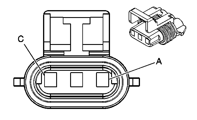
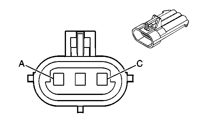
A | GRY | 1056 | Steering Wheel Position Sensor 5V Reference Voltage | A | ORN | 1056 | Steering Wheel Position Sensor 5V Reference Voltage | ||||||||
B | BLK | 2626 | Brake Pressure Sensor Signal | B | BLK | 2626 | Brake Pressure Sensor Signal | ||||||||
C | ORN/BLK | 556 | Low Reference | C | GRY | 556 | Low Reference | ||||||||

| |||||||||||||||
|---|---|---|---|---|---|---|---|---|---|---|---|---|---|---|---|
Connector Part Information |
| Connector Part Information |
| ||||||||||||
Pin | Wire Color | Circuit No. | Function | Pin | Wire Color | Circuit No. | Function | ||||||||
A | ORN | 2240 | Battery Positive Voltage | A | ORN | 2240 | Battery Positive Voltage | ||||||||
B | BLK | 150 | Ground | B | BLK | 150 | Ground | ||||||||
C | ORN | 2340 | Battery Positive Voltage | C | ORN | 2340 | Battery Positive Voltage | ||||||||
D | TAN | 1047 | PDM Class 2 Serial Data | D | TAN | 1047 | PDM Class 2 Serial Data | ||||||||
E | BLK | 150 | Ground | E | BLK | 150 | Ground | ||||||||
F | BLK/WHT | 746 | Right Front Door Ajar Switch Signal | F | BLK/WHT | 746 | Right Front Door Ajar Switch Signal | ||||||||
F | BLK/WHT | 746 | Right Front Door Ajar Switch Signal | ||||||||||||

| |||||||||||||||
|---|---|---|---|---|---|---|---|---|---|---|---|---|---|---|---|
Connector Part Information |
| Connector Part Information |
| ||||||||||||
Pin | Wire Color | Circuit No. | Function | Pin | Wire Color | Circuit No. | Function | ||||||||
A | ORN | 2640 | Battery Positive Voltage | A | ORN | 2640 | Battery Positive Voltage | ||||||||
B | BLK | 150 | Ground | B | BLK | 150 | Ground | ||||||||
C | ORN | 2140 | Battery Positive Voltage | C | ORN | 2140 | Battery Positive Voltage | ||||||||
D | BRN | 1046 | DDM Class 2 Serial Data | D | BRN | 1046 | DDM Class 2 Serial Data | ||||||||
E | BLK | 150 | Ground | E | BLK | 150 | Ground | ||||||||
F | GRY/BLK | 745 | Left Front Door Ajar Switch Signal | F | GRY/BLK | 745 | Left Front Door Ajar Switch Signal | ||||||||
F | GRY/BLK | 745 | Left Front Door Ajar Switch Signal | ||||||||||||

| |||||||||||||||
|---|---|---|---|---|---|---|---|---|---|---|---|---|---|---|---|
Connector Part Information |
| Connector Part Information |
| ||||||||||||
Pin | Wire Color | Circuit No. | Function | Pin | Wire Color | Circuit No. | Function | ||||||||
A | LT GRN | 200 | Right Front Speaker Output (+) | A | LT GRN | 200 | Right Front Speaker Output (+) | ||||||||
B | DK GRN | 117 | Right Front Speaker Output (-) | B | DK GRN | 117 | Right Front Speaker Output (-) | ||||||||
C | BLK/WHT | 351 | Ground | C | BLK/WHT | 351 | Ground | ||||||||
D | ORN | 360 | Speaker Supply Voltage | D | ORN | 360 | Speaker Supply Voltage | ||||||||
E | BLK/WHT | 351 | Ground | E | BLK/WHT | 351 | Ground | ||||||||
F-G | -- | -- | Not Used | F-G | -- | -- | Not Used | ||||||||
H | ORN/BLK | 1726 | Audio Signal-RH Subwoofer | H | YEL | 1726 | Audio Signal-RH Subwoofer | ||||||||
J | LT GRN | 512 | Right Front Low Level Audio Signal (+) | J | LT GRN | 512 | Right Front Low Level Audio Signal (+) | ||||||||
K | BARE | 514 | Ground | K | BARE | 514 | Ground | ||||||||

| |||||||||||||||
|---|---|---|---|---|---|---|---|---|---|---|---|---|---|---|---|
Connector Part Information |
| Connector Part Information |
| ||||||||||||
Pin | Wire Color | Circuit No. | Function | Pin | Wire Color | Circuit No. | Function | ||||||||
A | TAN | 201 | Left Front Speaker Output (+) | A | TAN | 201 | Left Front Speaker Output (+) | ||||||||
B | GRY | 118 | Left Front Speaker Output (-) | B | GRY | 118 | Left Front Speaker Output (-) | ||||||||
C | BLK/WHT | 351 | Ground | C | BLK/WHT | 351 | Ground | ||||||||
D | ORN | 360 | Speaker Supply Voltage | D | ORN | 360 | Speaker Supply Voltage | ||||||||
E | BLK/WHT | 351 | Ground | E | BLK/WHT | 351 | Ground | ||||||||
F | GRY | 1690 | Automatic Day-Night Mirror Signal | F | GRY | 1690 | Automatic Day-Night Mirror Signal | ||||||||
G | PNK | 1691 | Automatic Day-Night Mirror Low Reference | G | PNK | 1691 | Automatic Day-Night Mirror Low Reference | ||||||||
H | TAN | 511 | Left Front Low Level Audio Signal (+) | H | TAN | 511 | Left Front Low Level Audio Signal (+) | ||||||||
J | BLK | 1725 | Audio Signal-LH Subwoofer | J | BLK | 1725 | Audio Signal-LH Subwoofer | ||||||||
K | BARE | 514 | Ground | K | BARE | 514 | Ground | ||||||||

| |||||||||||||||
|---|---|---|---|---|---|---|---|---|---|---|---|---|---|---|---|
Connector Part Information |
| Connector Part Information |
| ||||||||||||
Pin | Wire Color | Circuit No. | Function | Pin | Wire Color | Circuit No. | Function | ||||||||
A | BRN/WHT | 367 | Remote Radio Left Audio Signal | A | BRN/WHT | 367 | Remote Radio Left Audio Signal | ||||||||
B | DK GRN /WHT | 368 | Remote Radio Right Audio Signal | B | DK GRN /WHT | 368 | Remote Radio Right Audio Signal | ||||||||
C | BLK/WHT | 372 | Remote Radio Audio Output (-) | C | BLK/WHT | 372 | Remote Radio Audio Output (-) | ||||||||
D | BARE | 514 | Ground | D | BARE | 514 | Ground | ||||||||

| |||||||||||||||
|---|---|---|---|---|---|---|---|---|---|---|---|---|---|---|---|
Connector Part Information |
| Connector Part Information |
| ||||||||||||
Pin | Wire Color | Circuit No. | Function | Pin | Wire Color | Circuit No. | Function | ||||||||
A | ORN | 840 | Battery Positive Voltage | A | ORN | 840 | Battery Positive Voltage | ||||||||
B | YEL | 443 | Accessory Voltage | B | YEL | 443 | Accessory Voltage | ||||||||
C | BLK | 150 | Ground | C | BLK | 150 | Ground | ||||||||

| |||||||||||||||
|---|---|---|---|---|---|---|---|---|---|---|---|---|---|---|---|
Connector Part Information |
| Connector Part Information |
| ||||||||||||
Pin | Wire Color | Circuit No. | Function | Pin | Wire Color | Circuit No. | Function | ||||||||
A | BLK | 150 | Ground | A | BLK | 150 | Ground | ||||||||
B | LT GRN | 1601 | Steering Column Lock Signal | B | LT GRN | 1601 | Steering Column Lock Signal | ||||||||
C | PPL | 1604 | Steering Column Unlock | C | PPL | 1604 | Steering Column Unlock | ||||||||
D | ORN | 2630 | Steering Column Lock (Domestic and Export Manual Transmission) | D | WHT | 2630 | Steering Column Lock (Domestic and Export Manual Transmission) | ||||||||
ORN | 1603 | Steering Column Lock (Domestic Automatic Transmission) | ORN | 1603 | Steering Column Lock (Domestic Automatic Transmission) | ||||||||||

| |||||||||||||||
|---|---|---|---|---|---|---|---|---|---|---|---|---|---|---|---|
Connector Part Information |
| Connector Part Information |
| ||||||||||||
Pin | Wire Color | Circuit No. | Function | Pin | Wire Color | Circuit No. | Function | ||||||||
A | ORN | 2094 | Steering Column Tilt and Telescope Forward Switch Signal | A | PNK | 2094 | Steering Column Tilt and Telescope Forward Switch Signal | ||||||||
B | PNK | 2095 | Steering Column Tilt and Telescope Reverse Switch Signal | B | ORN | 2095 | Steering Column Tilt and Telescope Reverse Switch Signal | ||||||||
C | BLK | 150 | Ground | C | BLK | 150 | Ground | ||||||||

| |||||||||||||||
|---|---|---|---|---|---|---|---|---|---|---|---|---|---|---|---|
Connector Part Information |
| Connector Part Information |
| ||||||||||||
Pin | Wire Color | Circuit No. | Function | Pin | Wire Color | Circuit No. | Function | ||||||||
A | WHT | 27 | Hazard Flasher Signal | A | BRN | 27 | Hazard Flasher Signal | ||||||||
B | DK GRN | 19 | Right Rear Stop/Turn Lamp Supply Voltage | B | DK GRN | 19 | Right Rear Stop/Turn Lamp Supply Voltage | ||||||||
C | YEL | 18 | Left Rear Stop/Turn Lamp Supply Voltage | C | YEL | 18 | Left Rear Stop/Turn Lamp Supply Voltage | ||||||||
D | PPL | 16 | Turn Signal Flasher Signal | D | PPL | 16 | Turn Signal Flasher Signal | ||||||||
E | -- | -- | Not Used | E | -- | -- | Not Used | ||||||||
F | DK BLU | 15 | Right Turn Signal Status Signal | F | DK BLU | 15 | Right Turn Signal Status Signal | ||||||||
G | LT BLU | 14 | Left Turn Signal Status Signal | G | LT BLU | 14 | Left Turn Signal Status Signal | ||||||||
H | DK BLU | 38 | Backup Lamp Relay Control | H | DK BLU | 38 | Backup Lamp Relay Control | ||||||||
J | BLK | 58 | Right Cornering Lamp Supply Voltage | J | BLK | 58 | Right Cornering Lamp Supply Voltage | ||||||||
K | LT GRN | 11 | Headlamp High Beam Supply Voltage | K | LT GRN | 11 | Headlamp High Beam Supply Voltage | ||||||||
LT GRN | 11 | Headlamp High Beam Supply Voltage | |||||||||||||
L | TAN | 12 | Headlamp Low Beam Supply Voltage | L | TAN | 12 | Headlamp Low Beam Supply Voltage | ||||||||
M | -- | -- | Not Used | M | -- | -- | Not Used | ||||||||
N | BLK | 150 | Ground | N | BLK | 150 | Ground | ||||||||
P | -- | -- | Not Used | P | -- | -- | Not Used | ||||||||
R | BRN | 9 | Park Lamp Supply Voltage | R | BRN | 9 | Park Lamp Supply Voltage | ||||||||
S | WHT | 103 | Headlamp Switch Headlamps On Signal | S | WHT | 103 | Headlamp Switch Headlamps On Signal | ||||||||
T | DK GRN | 306 | Headlamp Switch Headlamps Off Signal | T | DK GRN | 306 | Headlamp Switch Headlamps Off Signal | ||||||||
U | ORN | 57 | Left Cornering Lamp Supply Voltage | U | ORN | 57 | Left Cornering Lamp Supply Voltage | ||||||||
V | BLK | 28 | Horn Relay Control | V | BLK | 28 | Horn Relay Control | ||||||||
W | RED | 842 | Battery Positive Voltage | W | RED | 842 | Battery Positive Voltage | ||||||||
X | RED | 842 | Battery Positive Voltage | X | RED | 842 | Battery Positive Voltage | ||||||||
Y | LT BLU | 74 | Park Lamp Switch Signal | Y | LT BLU | 74 | Park Lamp Switch Signal | ||||||||
Z | ORN | 240 | Battery Positive Voltage | Z | ORN | 240 | Battery Positive Voltage | ||||||||

| |||||||||||||||
|---|---|---|---|---|---|---|---|---|---|---|---|---|---|---|---|
Connector Part Information |
| Connector Part Information |
| ||||||||||||
Pin | Wire Color | Circuit No. | Function | Pin | Wire Color | Circuit No. | Function | ||||||||
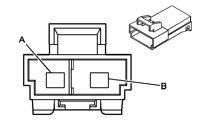
A | RED | 2098 | Steering Column Telescope Motor Forward | A | RED | 2098 | Steering Column Telescope Motor Forward | ||||||||
B | BLK | 2110 | Steering Column Telescope Motor Reverse | B | BLK | 2110 | Steering Column Telescope Motor Reverse | ||||||||
| |||||||||||||||
|---|---|---|---|---|---|---|---|---|---|---|---|---|---|---|---|
Connector Part Information |
| Connector Part Information |
| ||||||||||||
Pin | Wire Color | Circuit No. | Function | Pin | Wire Color | Circuit No. | Function | ||||||||
A | WHT | 347 | Steering Wheel Module - High Control | A | WHT | 347 | Steering Wheel Module - High Control | ||||||||
B | DK GRN | 348 | Steering Wheel Module - Low Control | B | DK GRN | 348 | Steering Wheel Module - Low Control | ||||||||

| |||||||||||||||
|---|---|---|---|---|---|---|---|---|---|---|---|---|---|---|---|
Connector Part Information |
| Connector Part Information |
| ||||||||||||
Pin | Wire Color | Circuit No. | Function | Pin | Wire Color | Circuit No. | Function | ||||||||
A | PPL | 1985 | 5 Volt Reference | A | PPL | 1985 | 5 Volt Reference | ||||||||
B | BLK | 782 | Memory Seat/Mirror Sensor Low Reference | B | BLK | 782 | Memory Seat/Mirror Sensor Low Reference | ||||||||
C | ORN | 2153 | Steering Column Telescope Motor Signal | C | ORN | 2153 | Steering Column Telescope Motor Signal | ||||||||

| |||||||||||||||
|---|---|---|---|---|---|---|---|---|---|---|---|---|---|---|---|
Connector Part Information |
| Connector Part Information |
| ||||||||||||
Pin | Wire Color | Circuit No. | Function | Pin | Wire Color | Circuit No. | Function | ||||||||
A | WHT/BLK | 1403 | I/P Module - High Control | A | WHT/BLK | 1403 | I/P Module - High Control | ||||||||
B | DK GRN /WHT | 1404 | I/P Module - Low Control | B | DK GRN /WHT | 1404 | I/P Module - Low Control | ||||||||

| |||||||||||||||
|---|---|---|---|---|---|---|---|---|---|---|---|---|---|---|---|
Connector Part Information |
| Connector Part Information |
| ||||||||||||
Pin | Wire Color | Circuit No. | Function | Pin | Wire Color | Circuit No. | Function | ||||||||
A | BLK | 150 | Ground | A | BLK | 150 | Ground | ||||||||
B | ORN | 140 | Battery Positive Voltage | B | ORN | 140 | Battery Positive Voltage | ||||||||
C | PNK | 1739 | Ignition 1 Voltage | C | PNK | 1739 | Ignition 1 Voltage | ||||||||
D | -- | -- | Not Used | D | -- | -- | Not Used | ||||||||
E | GRY/BLK | 1458 | Hazard Switch Signal | E | GRY/BLK | 1458 | Hazard Switch Signal | ||||||||
F | LT BLU | 14 | Left Turn Signal Status Signal | F | LT BLU | 14 | Left Turn Signal Status Signal | ||||||||
G | DK BLU | 15 | Right Turn Signal Status Signal | G | DK BLU | 15 | Right Turn Signal Status Signal | ||||||||
H | PPL | 16 | Turn Signal Flasher Signal | H | PPL | 16 | Turn Signal Flasher Signal | ||||||||
J | BRN | 27 | Hazard Flasher Signal | J | BRN | 27 | Hazard Flasher Signal | ||||||||
K | WHT | 17 | Stoplamp Switch Signal | K | WHT | 17 | Stoplamp Switch Signal | ||||||||

| |||||||||||||||
|---|---|---|---|---|---|---|---|---|---|---|---|---|---|---|---|
Connector Part Information |
| Connector Part Information |
| ||||||||||||
Pin | Wire Color | Circuit No. | Function | Pin | Wire Color | Circuit No. | Function | ||||||||
A | GRY | 397 | Cruise Control On Switch Signal | A | GRY | 397 | Cruise Control On Switch Signal | ||||||||
B | PNK/BLK | 1239 | Ignition 1 Voltage | B | PNK | 1239 | Ignition 1 Voltage | ||||||||
C | DK BLU | 84 | Cruise Control Set/Coast Switch Signal | C | DK BLU | 84 | Cruise Control Set/Coast Switch Signal | ||||||||
D | GRY/BLK | 87 | Cruise Control Resume/Accel Switch Signal | D | GRY/BLK | 87 | Cruise Control Resume/Accel Switch Signal | ||||||||

| |||||||||||||||
|---|---|---|---|---|---|---|---|---|---|---|---|---|---|---|---|
Connector Part Information |
| Connector Part Information |
| ||||||||||||
Pin | Wire Color | Circuit No. | Function | Pin | Wire Color | Circuit No. | Function | ||||||||
A | DK GRN | 95 | Windshield Wiper Motor Low Speed | A | DK GRN | 95 | Windshield Wiper Motor Low Speed | ||||||||
B | GRY | 91 | Windshield Wiper Switch Signal 2 | B | GRY | 91 | Windshield Wiper Switch Signal 2 | ||||||||
C | YEL | 143 | Accessory Voltage | C | YEL | 143 | Accessory Voltage | ||||||||
YEL | 143 | Accessory Voltage | |||||||||||||
D | PPL | 92 | Windshield Wiper Motor High Speed | D | PPL | 92 | Windshield Wiper Motor High Speed | ||||||||
E | PNK | 94 | Windshield Washer Switch Signal | E | PNK | 94 | Windshield Washer Switch Signal | ||||||||
F | -- | -- | Not Used | F | -- | -- | Not Used | ||||||||

| |||||||||||||||
|---|---|---|---|---|---|---|---|---|---|---|---|---|---|---|---|
Connector Part Information |
| Connector Part Information |
| ||||||||||||
Pin | Wire Color | Circuit No. | Function | Pin | Wire Color | Circuit No. | Function | ||||||||
A | ORN | 640 | Battery Positive Voltage | A | ORN | 640 | Battery Positive Voltage | ||||||||
B | BLK | 150 | Ground | B | BLK | 150 | Ground | ||||||||
C | LT GRN | 24 | Backup Lamp Supply Voltage | C | LT GRN | 24 | Backup Lamp Supply Voltage | ||||||||
D | GRY | 1690 | Automatic Day/Night Mirror Signal | D | GRY | 1690 | Automatic Day/Night Mirror Signal | ||||||||
E | PNK | 1691 | Automatic Day/Night Mirror Low Reference | E | PNK | 1691 | Automatic Day/Night Mirror Low Reference | ||||||||
F | ORN | 740 | Battery Positive Voltage | F | ORN | 740 | Battery Positive Voltage | ||||||||
G | BRN | 341 | Ignition 3 Voltage | G | BRN | 341 | Ignition 3 Voltage | ||||||||
H | -- | -- | Not Used | H | -- | -- | Not Used | ||||||||

| |||||||||||||||
|---|---|---|---|---|---|---|---|---|---|---|---|---|---|---|---|
Connector Part Information |
| Connector Part Information |
| ||||||||||||
Pin | Wire Color | Circuit No. | Function | Pin | Wire Color | Circuit No. | Function | ||||||||
A | BLK/WHT | 238 | Seat Belt Switch Signal -Driver | A | BLK/WHT | 238 | Seat Belt Switch Signal -Driver | ||||||||
BLK/WHT | 238 | Seat Belt Switch Signal -Driver | |||||||||||||
B | BRN/WHT | 1048 | SCM (Seat) Class 2 Serial Data | B | BRN/WHT | 1048 | SCM (Seat) Class 2 Serial Data | ||||||||
C | ORN | 1840 | Battery Positive Voltage | C | ORN | 1840 | Battery Positive Voltage | ||||||||
D | BLK | 150 | Ground | D | BLK | 150 | Ground | ||||||||
BLK | 150 | Ground (W/AR9) | |||||||||||||
E | ORN | 1740 | Battery Positive Voltage | E | ORN | 1740 | Battery Positive Voltage | ||||||||
ORN | 1740 | Battery Positive Voltage | |||||||||||||
F | ORN | 1140 | Battery Positive Voltage | F | ORN | 1140 | Battery Positive Voltage | ||||||||

| |||||||||||||||
|---|---|---|---|---|---|---|---|---|---|---|---|---|---|---|---|
Connector Part Information |
| Connector Part Information |
| ||||||||||||
Pin | Wire Color | Circuit No. | Function | Pin | Wire Color | Circuit No. | Function | ||||||||
A-B | -- | -- | Not Used | A-B | -- | -- | Not Used | ||||||||
C | ORN | 1440 | Battery Positive Voltage | C | ORN | 1440 | Battery Positive Voltage | ||||||||
D | BLK | 150 | Ground | D | BLK | 150 | Ground | ||||||||
BLK | 150 | Ground | |||||||||||||
E | -- | -- | Not Used | E | -- | -- | Not Used | ||||||||
F | ORN | 1140 | Battery Positive Voltage | F | ORN/BLK | 1140 | Battery Positive Voltage | ||||||||

| |||||||||||||||
|---|---|---|---|---|---|---|---|---|---|---|---|---|---|---|---|
Connector Part Information |
| Connector Part Information |
| ||||||||||||
Pin | Wire Color | Circuit No. | Function | Pin | Wire Color | Circuit No. | Function | ||||||||
A | RED | 2098 | Steering Column Telescope Motor Forward | A | RED | 2098 | Steering Column Telescope Motor Forward | ||||||||
B | BLK | 2110 | Steering Column Telescope Motor Reverse | B | BLK | 2110 | Steering Column Telescope Motor Reverse | ||||||||
C | PPL | 1985 | Steering Column Telescope Motor 5 Volt Reference | C | PPL | 1985 | Steering Column Telescope Motor 5 Volt Reference | ||||||||
D | BLK | 782 | Memory Seat/Mirror Sensor Low Reference | D | BLK | 782 | Memory Seat/Mirror Sensor Low Reference | ||||||||
E | ORN | 2153 | Steering Column Telescope Motor Signal | E | ORN | 2153 | Steering Column Telescope Motor Signal | ||||||||
F | PNK | 2094 | Steering Column Tilt and Telescope Forward Switch Signal | F | PNK | 2094 | Steering Column Tilt and Telescope Forward Switch Signal | ||||||||
G | ORN | 2095 | Steering Column Tilt and Telescope Reverse Switch Signal | G | ORN | 2095 | Steering Column Tilt and Telescope Reverse Switch Signal | ||||||||
H | -- | -- | Not Used | H | -- | -- | Not Used | ||||||||

| |||||||||||||||
|---|---|---|---|---|---|---|---|---|---|---|---|---|---|---|---|
Connector Part Information |
| Connector Part Information |
| ||||||||||||
Pin | Wire Color | Circuit No. | Function | Pin | Wire Color | Circuit No. | Function | ||||||||
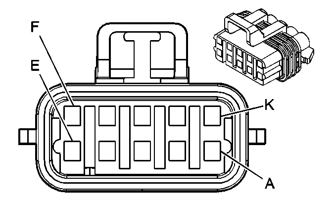
A | BLK | 150 | Ground | A | BLK | 150 | Ground | ||||||||
B | YEL | 820 | CHMSL Supply Voltage | B | YEL | 820 | CHMSL Supply Voltage | ||||||||
C | LT GRN | 24 | Backup Lamp Supply Voltage | C | LT GRN | 24 | Backup Lamp Supply Voltage | ||||||||
D | YEL | 18 | Left Rear Stop/Turn Lamp Supply Voltage | D | YEL | 18 | Left Rear Stop/Turn Lamp Supply Voltage | ||||||||
E | BRN | 9 | Park Lamp Supply Voltage | E | BRN | 9 | Park Lamp Supply Voltage | ||||||||
F | -- | -- | Not Used | F | -- | -- | Not Used | ||||||||
G | DK GRN | 19 | Right Rear Stop/Turn Lamp Supply Voltage | G | DK GRN | 19 | Right Rear Stop/Turn Lamp Supply Voltage | ||||||||
H | RED | 122 | Rear Fog Lamp Supply Voltage (Europe) | H | RED | 122 | Rear Fog Lamp Supply Voltage (Europe) | ||||||||
|
| ||||||||||||||
|---|---|---|---|---|---|---|---|---|---|---|---|---|---|---|---|
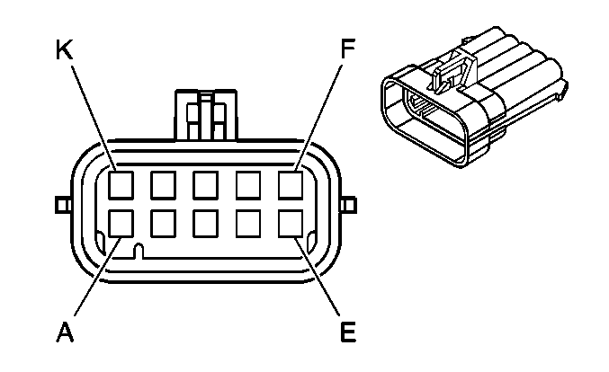
Connector Part Information |
| Connector Part Information |
| ||||||||||||
Pin | Wire Color | Circuit No. | Function | Pin | Wire Color | Circuit No. | Function | ||||||||
A | PNK | 339 | Ignition 1 Voltage | A | PNK | 339 | Ignition 1 Voltage | ||||||||
B | WHT | 1310 | EVAP Canister Vent Solenoid Control | B | WHT | 1310 | EVAP Canister Vent Solenoid Control | ||||||||
C | GRY | 720 | Low Reference | C | GRY | 720 | Low Reference | ||||||||
D | DK GRN | 890 | Fuel Tank Pressure Sensor Signal | D | DK GRN | 890 | Fuel Tank Pressure Sensor Signal | ||||||||
E | GRY/BLK | 598 | 5 Volt Reference | E | GRY | 598 | 5 Volt Reference | ||||||||
F | BLK | 150 | Ground | F | BLK | 150 | Ground | ||||||||
G | GRY | 120 | Fuel Pump Supply Voltage | G | GRY | 120 | Fuel Pump Supply Voltage | ||||||||
H | DK BLU | 1936 | Fuel Level Sensor Signal-Primary | H | DK BLU | 1936 | Fuel Level Sensor Signal-Primary | ||||||||
J | LT BLU | 1937 | Fuel Level Sensor Signal-Secondary | J | LT BLU | 1937 | Fuel Level Sensor Signal-Secondary | ||||||||
K | -- | -- | Not Used | K | -- | -- | Not Used | ||||||||

|

| ||||||||||||||
|---|---|---|---|---|---|---|---|---|---|---|---|---|---|---|---|
Connector Part Information |
| Connector Part Information |
| ||||||||||||
Pin | Wire Color | Circuit No. | Function | Pin | Wire Color | Circuit No. | Function | ||||||||
A | RED | 901 | Left Rear Suspension Damper Solenoid Control | A | DK BLU/WHT | 1114 | Left Rear Suspension Damper Solenoid Control | ||||||||
B | BLK | 902 | Left Rear Suspension Damper Solenoid Low Reference | B | DK GRN | 1115 | Left Rear Suspension Damper Solenoid Low Reference | ||||||||

|

| ||||||||||||||
|---|---|---|---|---|---|---|---|---|---|---|---|---|---|---|---|
Connector Part Information |
| Connector Part Information |
| ||||||||||||
Pin | Wire Color | Circuit No. | Function | Pin | Wire Color | Circuit No. | Function | ||||||||
A | RED | 901 | Right Rear Suspension Damper Solenoid Control | A | DK BLU/WHT | 1118 | Right Rear Suspension Damper Solenoid Control | ||||||||
B | BLK | 902 | Right Rear Suspension Damper Solenoid Low Reference | B | DK GRN | 1119 | Right Rear Suspension Damper Solenoid Low Reference | ||||||||

| |||||||||||||||
|---|---|---|---|---|---|---|---|---|---|---|---|---|---|---|---|
Connector Part Information |
| Connector Part Information |
| ||||||||||||
Pin | Wire Color | Circuit No. | Function | Pin | Wire Color | Circuit No. | Function | ||||||||
A | GRY | 720 | Low Reference | A | GRY | 720 | Low Reference | ||||||||
B | DK GRN | 890 | Fuel Tank Pressure Sensor Signal | B | DK GRN | 890 | Fuel Tank Pressure Sensor Signal | ||||||||
C | GRY/BLK | 598 | 5 Volt Reference | C | GRY/BLK | 598 | 5 Volt Reference | ||||||||

| |||||||||||||||
|---|---|---|---|---|---|---|---|---|---|---|---|---|---|---|---|
Connector Part Information |
| Connector Part Information |
| ||||||||||||
Pin | Wire Color | Circuit No. | Function | Pin | Wire Color | Circuit No. | Function | ||||||||
A | BLK | 293 | Rear Defog Element Supply Voltage | A | BLK | 293 | Rear Defog Element Supply Voltage | ||||||||
|
| ||||||||||||||
|---|---|---|---|---|---|---|---|---|---|---|---|---|---|---|---|
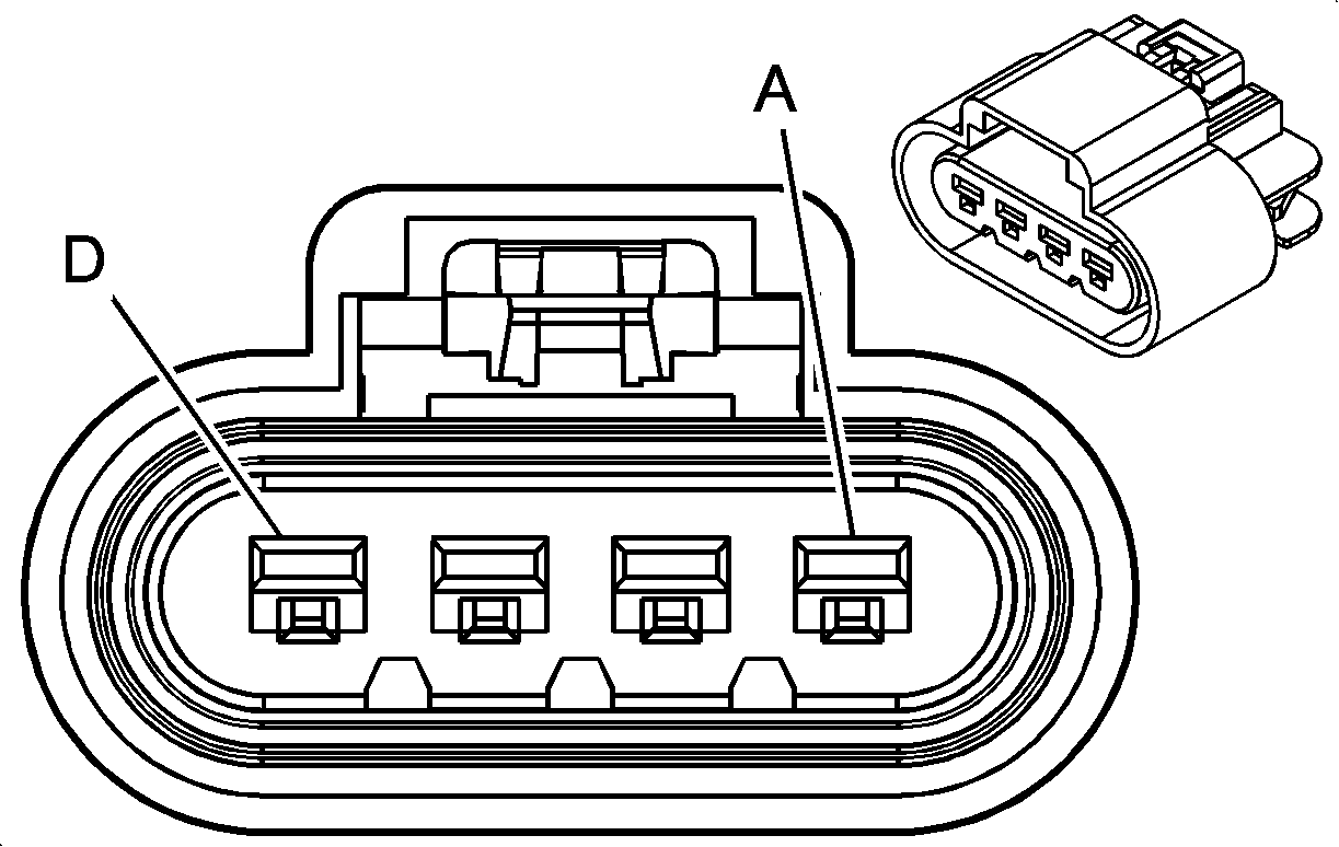
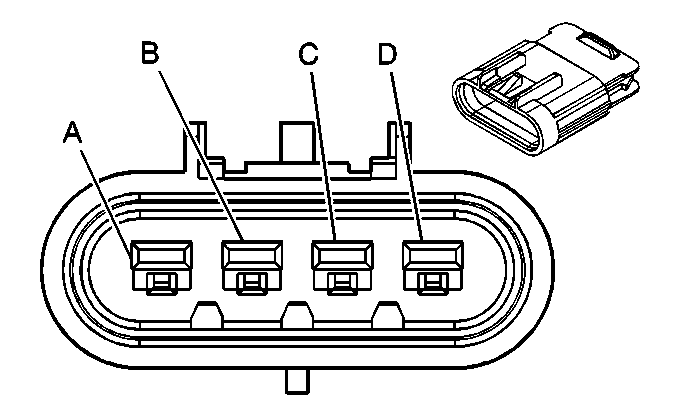
Connector Part Information |
| Connector Part Information |
| ||||||||||||
Pin | Wire Color | Circuit No. | Function | Pin | Wire Color | Circuit No. | Function | ||||||||
A | GRY | 120 | Fuel Pump Supply Voltage | A | GRY | 120 | Fuel Pump Supply Voltage | ||||||||
B | GRY | 720 | Low Reference | B | BLK | 808 | Low Reference | ||||||||
C | DK BLU | 1936 | Fuel Level Sensor Signal-Primary | C | DK BLU | 1936 | Fuel Level Sensor Signal-Primary | ||||||||
D | BLK | 150 | Ground | D | BLK | 9531 | Ground | ||||||||
|
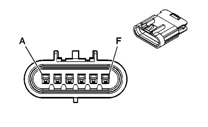
| ||||||||||||||
|---|---|---|---|---|---|---|---|---|---|---|---|---|---|---|---|
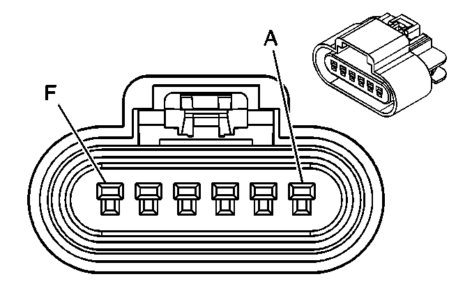
Connector Part Information |
| Connector Part Information |
| ||||||||||||
Pin | Wire Color | Circuit No. | Function | Pin | Wire Color | Circuit No. | Function | ||||||||
A | LT BLU | 1937 | Fuel Level Sensor Signal-Secondary | A | LT BLU | 1937 | Fuel Level Sensor Signal-Secondary | ||||||||
B | GRY | 720 | Low Reference | B | BLK | 808 | Low Reference | ||||||||
C | BLK | 150 | Ground | C | BLK/WHT | 850 | Ground | ||||||||
D | DK GRN | 890 | Fuel Tank Pressure Sensor Signal | D | DK GRN | 890 | Fuel Tank Pressure Sensor Signal | ||||||||
E | GRY/BLK | 598 | 5 Volt Reference | E | GRY | 2709 | 5 Volt Reference | ||||||||
F | -- | -- | Not Used | F | -- | -- | Not Used | ||||||||
