Tools Required
J 7872
Magnetic Base Dial Indicator Set
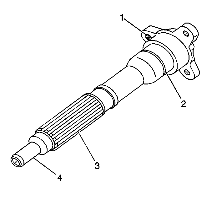
- Clean all bolts and bolt holes of threadlocking material.
- Clean the components in solvent.
Caution: Wear safety glasses in order to avoid eye damage.
- Dry the components with compressed air.
- Inspect the hub for the following conditions:
| • | Damaged bolt hole threads (1) |
| • | Damaged snap ring grooves (2) |
| • | Worn or scored surface (4) |
| • | Worn or damaged bushing |
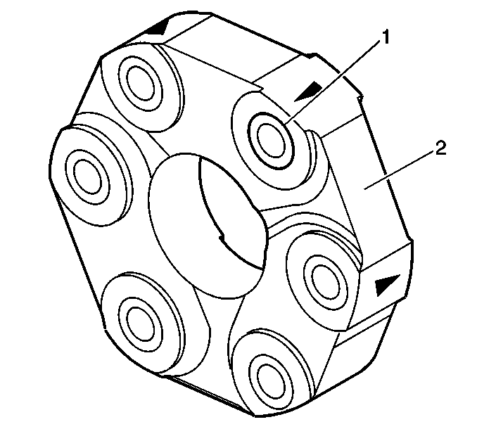
- Inspect the couplings for the following conditions:
| • | Loose or damaged inserts (1) |
| • | Worn, cracking, or deteriorated rubber (2) |
| • | MINOR cracking of the rubber is normal and acceptable. If the cracks expose any frayed fabric or internal windings, replace the coupling. |
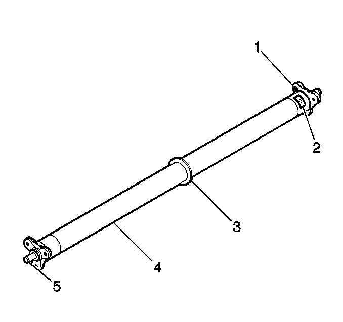
- Inspect the propeller shaft for the following conditions:
| • | Damaged bolt hole threads (1) |
| • | Loose or missing balance weights (2) |
| • | Balance weights may have been installed and removed during the balancing process. In those cases, a weld mark will remain on the propeller tube. |
| • | Inspect the inside of the driveline support tube for a missing balance weight. |
| • | Loose or damaged snubber (3) - manual transmission |
| • | Dented or damaged propeller shaft tube (4) |
| • | Worn, bent, loose, or damaged pins (5) |
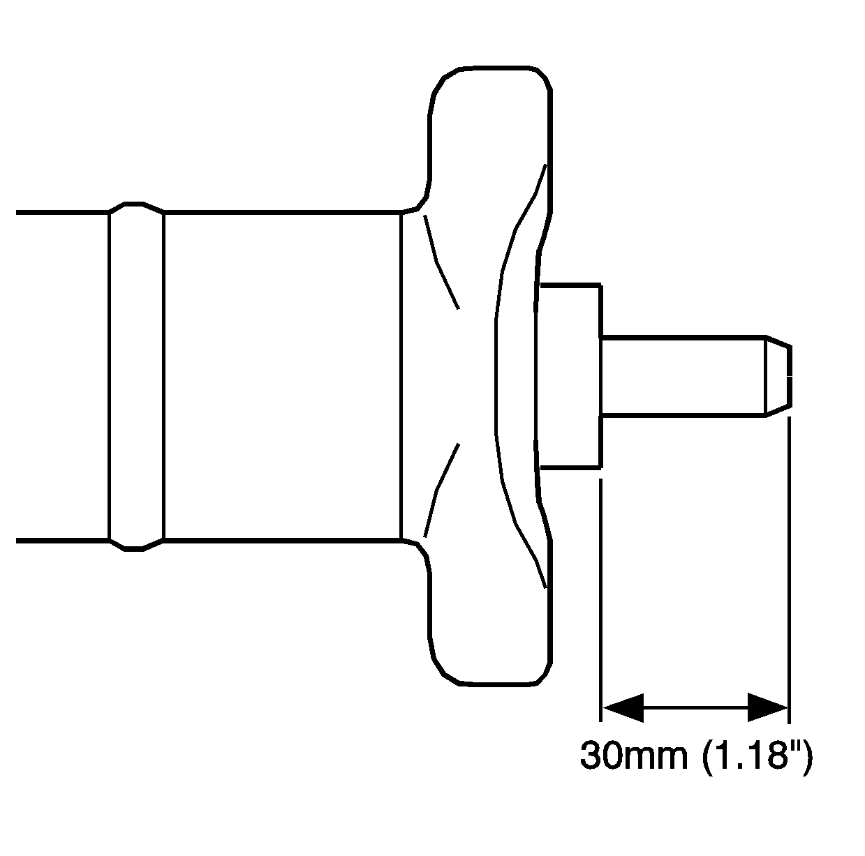
- Inspect the propeller shaft pins for proper installation. The pin should extend beyond the flange 30 mm
(1.18 in).
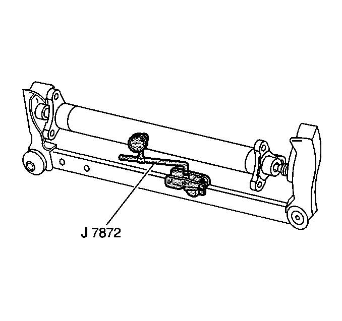
- Measure the propeller shaft runout.
| 8.1. | Mount the propeller shaft in wooden V-blocks or between centers on a fixture. |
| 8.2. | Check the runout of the propeller shaft in multiple locations, including the barrel ends, using the
J 7872
. |
| 8.3. | If propeller shaft runout exceeds 0.3 mm (0.118 in), the propeller shaft is bent and should be replaced. |
- Inspect the snubber - manual transmission - for wear or a flat spot on the outer edge.
- Check the runout of the snubber.
If the runout of the outer edge of the snubber exceeds 2 mm (0.79 in), replace the propeller shaft.
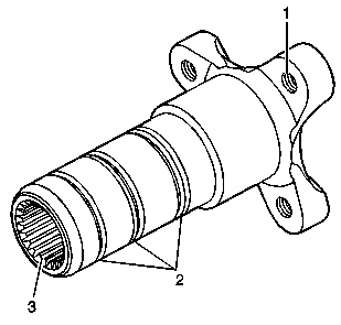
- Inspect the bearing housing hub for the following conditions:
| • | Damaged bolt hole threads (1) |
| • | Damaged snap ring grooves (2) |
| • | Worn or damaged splines (3) |
| • | Worn or damaged bushings |
| • | Bushings that have been removed from the hub will be damaged and should not be reused. Install NEW bushings during assembly. |
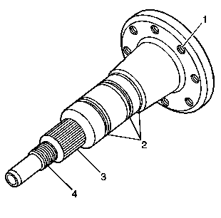
- Inspect the flex plate spindle - automatic transmission, for the following
conditions:
| • | Damaged bolt hole threads (1) |
| • | Damaged snap ring grooves (2) |
| • | Worn or damaged splines (3) |
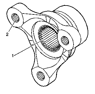
- Inspect the input hub - automatic transmission, for the following conditions:
| • | Worn or damaged splines (1) |
| • | Damaged bolt hole threads (2) |
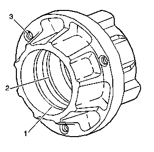
- Inspect the bearing housing for the following conditions:
| • | Damaged O-ring or snap ring grooves (1-2) |
| • | Worn or scored bearing bores |
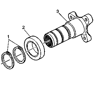
- Inspect the bearings for the following conditions:
| • | Excessive wear or roughness of operation |
| • | Bearings should rotate freely with no coarseness or rough feel |
- Inspect for bent or broken snap rings (1) and replace, as required.
- Inspect the driveline tube for the following conditions:
| • | Damaged bolt hole threads |
| • | Damaged front O-ring groove |
| • | Worn or scored front bearing bore |
| • | Missing or damaged bellhousing dowel pins |
| • | Damage to the exterior of the tube |


