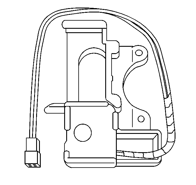
Tilt\Telescoping Description
The tilt/telescoping steering column uses the same tilt lever as the non-telescoping column and functions in the same manner. The telescoping function of this column consists of the telescoping drive motor, the telescoping actuator assembly and the telescoping actuator switch. The telescoping actuator assembly is cable driven by the telescoping drive motor. The telescoping actuator switch operates the inward or outward movement of the steering wheel.
The energy absorbing and locking steering column includes three important features in addition to the steering function.
- The steering column is energy absorbing and is designed to compress in a front-end collision which will lessen the chance of injury to the driver.
- The steering column has a telescoping control system that consists of an electronic control module capable of Class 2 serial data communication, a steering column power assembly with positioning motor and sensor, and a steering column control switch.
- The multi-function lever provides for the control of the headlamp high beams, and the windshield washer and wiper.
The steering column may be removed, disassembled and reassembled with relative ease. It is important to use only the specified screws, bolts and nuts and to tighten them to the specified torque in order to ensure the proper energy absorbing functions. When the steering column assembly is removed from the vehicle, special care must be taken in handling it. Avoid the use of a steering wheel puller other than the special one recommended in this manual. Sharply striking the end of the steering shaft, leaning on the assembly or dropping the assembly could shear off or loosen the plastic fasteners which maintain the steering column rigidity.
Tilt\Telescoping Operation
The telescoping steering column in/out switch is an input to the seat control module. The telescoping drive motor is an output function of the seat control module. The telescoping actuator assembly is cable driven by the telescoping drive motor.
Steering column memory settings are stored in the seat control module. The steering column position sensor is an internal part of the telescoping actuator assembly, and is an input to the seat control module. The seat control module uses the position sensor input when storing and recalling memory settings.
Memory steering column, and the easy enter/exit operations are performed by the seat control module. However the left door control module assumes control when memory settings are stored and recalled, by use of the serial data link. The body control module assumes control when the easy enter/exit operation occurs, by use of the serial data link.
The body control module stores the RPO code configuration which signals to the seat control module whether or not the telescoping steering column option is active. This RPO code configuration must be correct, and received by the seat control module, or power seat, and telescoping steering column operation will be inoperative or incorrect.
Steering Column Lock Description

The BCM provides the steering column control function which allows the column to be electronically locked or unlocked. The BCM provides three outputs, steering column lock, steering column unlock, and the external steering column lock relay. The BCM can apply a ground or battery output on the steering column lock circuit or steering column unlock circuit depending on the desired steering column lock motor position. The BCM accomplishes steering column lock motor operation based on the following output commands:
Steering Column Unlock | Steering Column Lock | Steering Column Lock Motor Operation |
|---|---|---|
GROUND | GROUND | NONE |
GROUND | BATTERY | UNLOCK |
BATTERY | GROUND | LOCK |
BATTERY | BATTERY | NONE |
The BCM controls the position of the steering column lock motor based on the following input information:
| • | Ignition position |
| • | Key in Ignition status |
| • | Key Out of Ignition status |
| • | Steering column lock feedback switch |
| • | PASS-Key® system |
| • | PCM password information |
| • | System voltage |
The external steering column lock relay is located above the BCM, in the passenger footwell area. The external steering column lock relay can be identified by 2 orange wires connected to it. There may be either 2 or 3 relays in this area, and they may not always be in the same position.
Steering Column Lock Operation
The BCM supplies the ground to the steering column unlock circuit through the key out of ignition switch which is integrated within the ignition switch. This prevents the BCM from locking the steering column with the key inthe ignition. The BCM supplies battery voltage to the steering column lock motor through BCM2 fuse. The BCM also controls the external steering column lock relay. The relay prevents the motor from operating unless the relay is energized. The BCM uses a feedback switch which is integrated within the steering column lock motor in order to monitor the motor position. The feedback switch allows the BCM to determine if the commanded position was actually accomplished. If the BCM is unable to determine the steering column lock state, due to a steering column lock system malfunction or by disconnecting the steering column motor with the ignition in the ON position, the BCM will enter a fail enable mode and prevent steering column lock operation. The PCM will also inhibit vehicle motion by disabling fuel. To clear the BCM fail enable mode, disconnect the BCM & IPC fuse in the I/P fuse block for 15 seconds. The BCM also monitors its circuitry for the column lock circuit. If the BCM detects a malfunction present the Driver Information Center (DIC) will display PULL KEY-WAIT 10 SEC. When the key is pulled out of the ignition for 10 seconds and then key is turned to the ON position the DIC will display SERVICE COLUMN LOCK and a DTC will set in the BCM memory. Always perform the BCM Diagnostic System Check before attempting any diagnosis on the steering column lock system.
