For 1990-2009 cars only
Removal Procedure
- Disconnect the negative battery cable. Refer to Battery Negative Cable Disconnection and Connection in Engine Electrical.
- Remove the right door sill plate. Refer to Door Sill Plate Replacement in Interior Trim.
- Remove the floor kick-up pad on the passenger side. Refer to Front Floor Kick-Up Panel Replacement in Interior Trim.
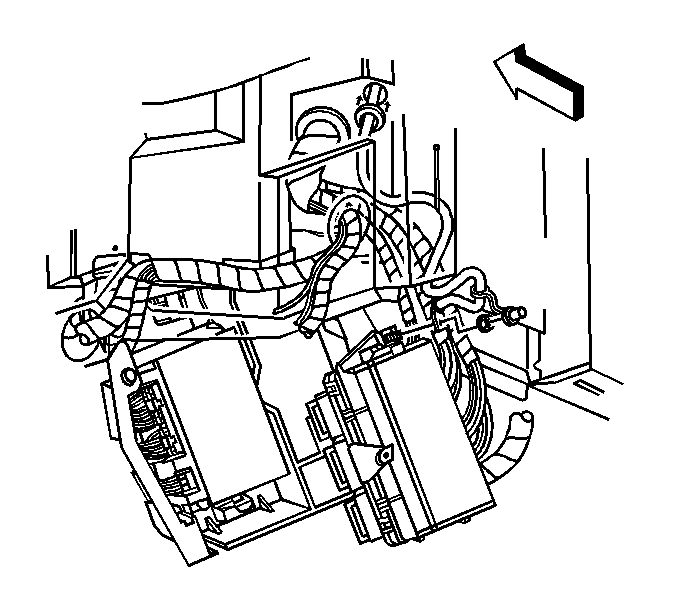
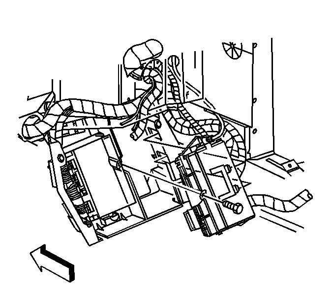
- Remove the retaining bolt which secures the multi-use bracket to the electrical wiring junction block.
- Disengage the retaining clip from the outboard side, twist the electrical wiring block, and pull outward.
- Remove the battery cable lead.
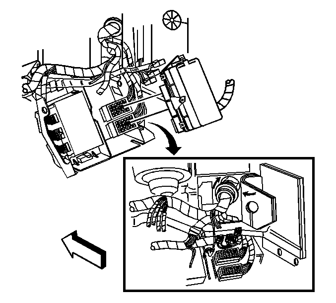
- Disconnect 3 64-way block connectors and 3 I/P wiring harness connectors.
- Transfer all fuses and relays as required.


Installation Procedure
- Position the electrical wiring junction block and connect 3 I/P wiring harness connectors and 3 64-way block connectors.
- Install the electrical wiring junction block to the multi-use bracket with the retaining bolt.
- Install the battery cable lead.
- Install the floor kick-up pad on the passenger side. Refer to Front Floor Kick-Up Panel Replacement in Interior Trim.
- Install the right door sill plate. Refer to Door Sill Plate Replacement in Interior Trim.
- Connect the negative battery cable. Refer to Battery Negative Cable Disconnection and Connection in Engine Electrical.

