Removal Procedure
- Disable the SIR system. Refer to SIR Disabling and Enabling in SIR.
- Disconnect the negative battery cable.
- Remove the console. Refer to Console Replacement .
- Remove the I/P accessory trim plate. Refer to Instrument Panel Accessory Trim Plate Replacement .
- Remove the driver knee bolster trim panel. Refer to Driver Knee Bolster Panel Replacement .
- Remove the I/P passenger compartment. Refer to Instrument Panel Compartment Replacement .
- Remove the I/P upper trim pad. Refer to Instrument Panel Upper Trim Pad Replacement .
- Remove the park/lock control cable (A/T). Refer to Park Lock Cable Replacement in Automatic Transmission - 4L60-E.
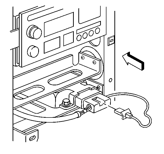
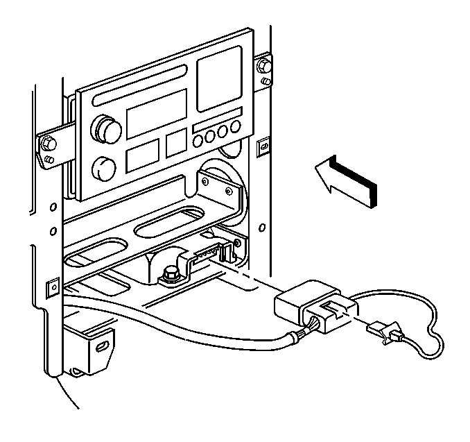
- Remove the connector position assurance (CPA) from the electrical connector on the inflatable restraint sensing and diagnostic module (SDM).
- Disconnect the SDM electrical connector.
- Remove the ignition switch bolts, then reposition the ignition switch. Refer to Ignition and Start Switch Replacement .
- Mark the location of the I/P center support bracket. Refer to Instrument Panel Disassembly Precautions .
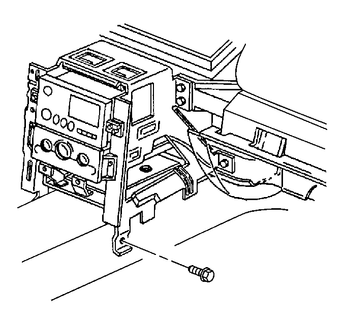
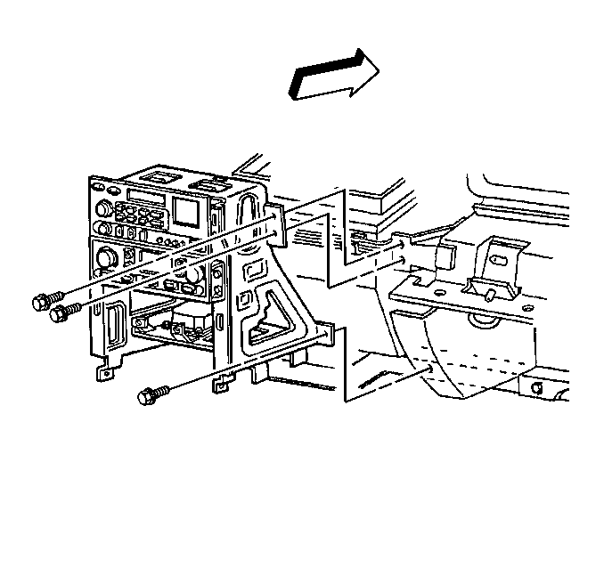
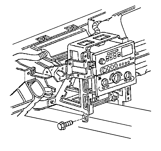
- Remove the right bolt that secures the center support bracket to the driveline tunnel.
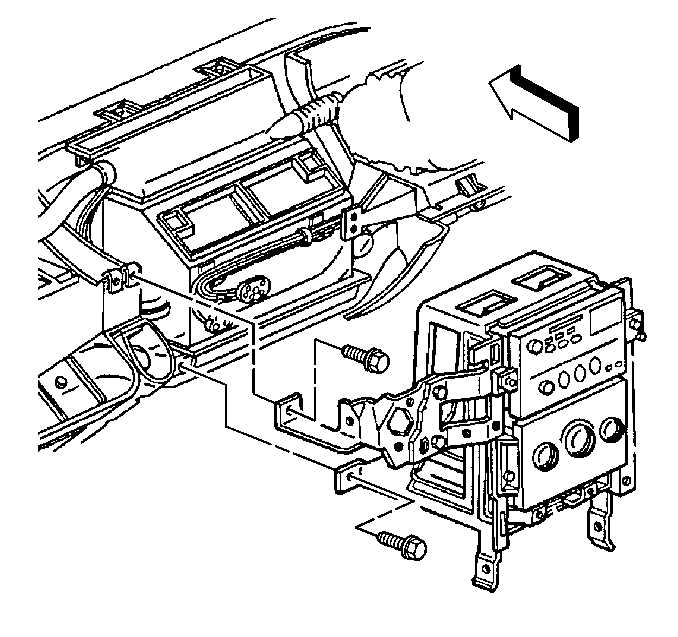
- Remove the bolts that secure the center support bracket to the passenger knee bolster bracket.
- Remove the right bolt that secures the center support bracket to the I/P lower support beam.
- Remove the right bolt that secures the center support bracket to the driveline tunnel.
- Mark the location of the ignition switch housing bracket. Refer to Instrument Panel Disassembly Precautions .
- Remove the bolt that secures the ignition switch housing bracket to the steering column bracket.
- Remove the left bolt that secures the center support bracket to the I/P lower support beam.
- Slowly pull the center support bracket away from the I/P to access the radio control and HVAC control connectors.
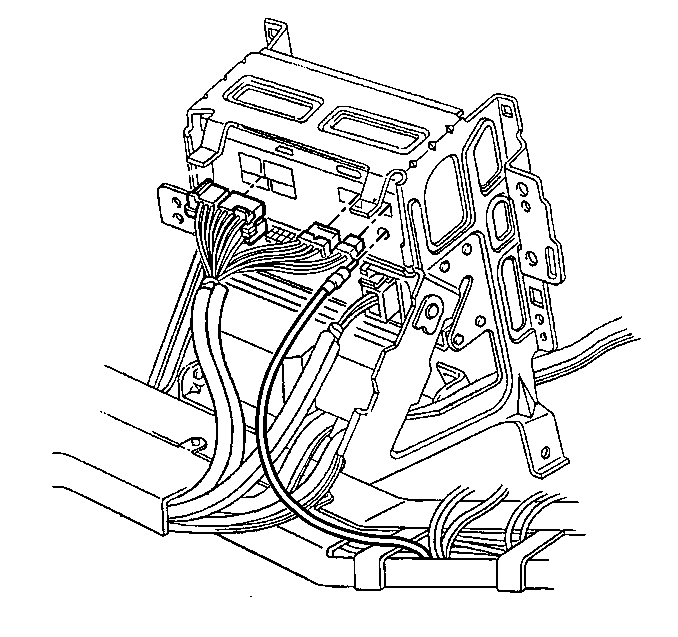
- Disconnect the connectors from the radio control electrical/audio and the coaxial cable.
- Disconnect the HVAC control electrical connectors and the vacuum harness connectors (C60).
- Release the I/P wiring harness retainer and the parking brake connector clip from the center support bracket.
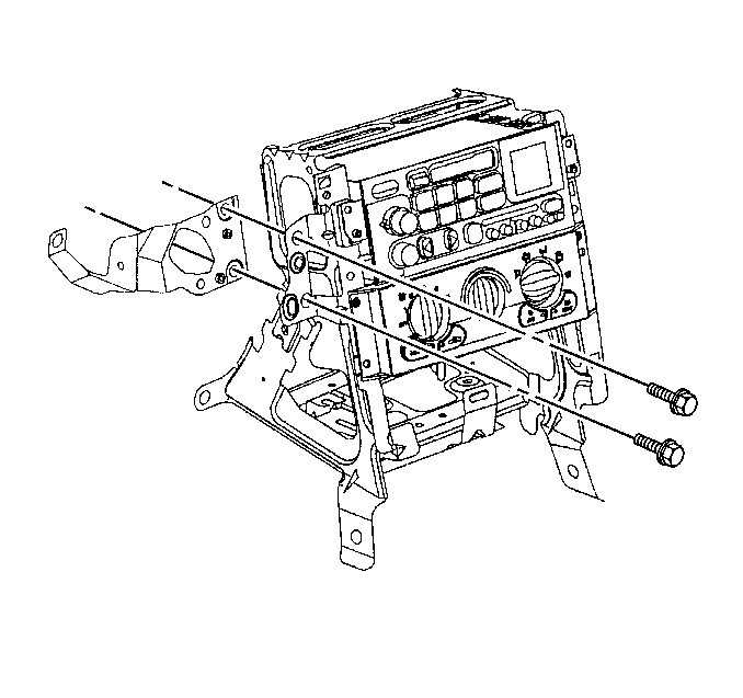
- Remove the bolts that secure the ignition switch housing bracket to the center support bracket.
- Remove the ignition switch housing bracket.
- Remove the I/P harness from the center support bracket.
- Remove the center support bracket from the vehicle.
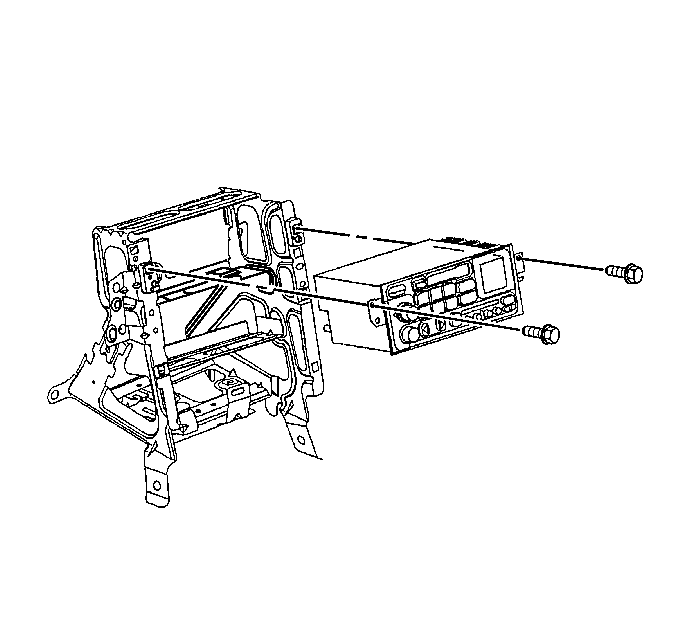
- Remove the radio control retaining screws.
- Remove the radio control from the center support bracket.
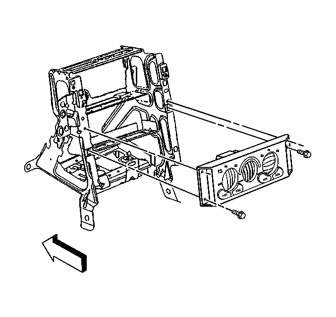
- Remove the HVAC control retaining screws.
- Remove the HVAC control from the center support bracket.
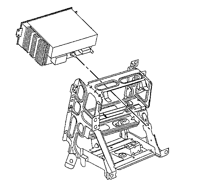
- Remove the SDM from the center support bracket. Refer to Inflatable Restraint Sensing and Diagnostic Module Replacement in SIR.
Caution: Unless directed otherwise, the ignition and start switch must be in the OFF or LOCK position, and all electrical loads must be OFF before servicing any electrical component. Disconnect the negative battery cable to prevent an electrical spark should a tool or equipment come in contact with an exposed electrical terminal. Failure to follow these precautions may result in personal injury and/or damage to the vehicle or its components.
Important: The following step must be performed to assure proper trim fit during installation.
Important: The following step must be performed to assure proper trim fit during installation.
Important: Take note of the I/P harness routing through the I/P center support bracket prior to removal.
Installation Procedure
- Install the SDM to the center support bracket. Refer to Inflatable Restraint Sensing and Diagnostic Module Replacement in SIR.
- Install the HVAC control to the center support bracket.
- Install the HVAC control retaining screws.
- Align the radio control locator to the center support bracket locator hole, then push to install the radio control.
- Install the radio control retaining screws.
- Position the ignition switch housing bracket to the center support bracket as marked prior to removal.
- Install the bolts that secure the ignition switch housing bracket to the center support bracket.
- Install the center support bracket to the vehicle.
- Install the I/P wiring harness to the center support bracket as noted prior to removal.
- Secure the I/P wiring harness retainer and the parking brake connector clip to the center support bracket.
- Connect the HVAC control electrical connectors and the vacuum harness connectors (C60).
- Connect the radio control electrical/audio connectors and the coaxial cable connectors.
- Install the center support bracket into position as marked prior to removal.
- Install the left bolt to secure the center support bracket to the I/P lower support beam.
- Position the ignition switch housing bracket to the steering column bracket as marked prior to removal.
- Install the bolt to secure the ignition switch housing bracket to the steering column bracket.
- Install the left bolt to secure the center support bracket to the driveline tunnel.
- Install the right bolt to secure the center support bracket to the I/P lower support beam.
- Install the bolts to secure the center support bracket to the passenger knee bolster bracket.
- Install the right bolts to secure the center support bracket to the driveline tunnel.
- Position and install the ignition switch to the ignition switch housing bracket. Refer to Ignition and Start Switch Replacement .
- Connect the SDM electrical connector.
- Install the CPA to the SDM electrical connector.
- Install the park/lock control cable (A/T). Refer to Park Lock Cable Replacement in Automatic Transmission.
- Install the I/P upper trim pad. Refer to Instrument Panel Upper Trim Pad Replacement .
- Install the I/P passenger compartment. Refer to Instrument Panel Compartment Replacement .
- Install the driver knee bolster trim panel. Refer to Driver Knee Bolster Panel Replacement .
- Install the I/P accessory trim plate. Refer to Instrument Panel Accessory Trim Plate Replacement .
- Install the console. Refer to Console Replacement .
- Connect the negative battery cable.
- Program the transmitters. Refer to Transmitter Synchronization and Transmitter Programming in Keyless Entry.
- Enable the SIR system. Refer to SIR Disabling and Enabling in SIR.

Notice: Use the correct fastener in the correct location. Replacement fasteners must be the correct part number for that application. Fasteners requiring replacement or fasteners requiring the use of thread locking compound or sealant are identified in the service procedure. Do not use paints, lubricants, or corrosion inhibitors on fasteners or fastener joint surfaces unless specified. These coatings affect fastener torque and joint clamping force and may damage the fastener. Use the correct tightening sequence and specifications when installing fasteners in order to avoid damage to parts and systems.
Tighten
Tighten the screws to 1.9 N·m (17 lb in).


Tighten
Tighten the screws to 2.5 N·m (22 lb in).

Tighten
Tighten the bolts to 12 N·m (106 lb in).


Tighten
Tighten the bolt to 12 N·m (106 lb in).
Tighten
Tighten the bolt to 1.9 N·m (17 lb in).

Tighten
Tighten the bolt to 12 N·m (106 lb in).

Tighten
Tighten the bolt to 12 N·m (106 lb in).
Tighten
Tighten the bolts to 12 N·m (106 lb in).

Tighten
Tighten the bolt to 12 N·m (106 lb in).


Tighten
Tighten the cable bolt to 15 N·m (11 lb ft).
