Driver or Passenger Seat Replacement Power
Removal Procedure
- Place a protective cover
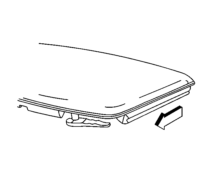
over the sill plate and door trim panel and/or remove the roof lift off panel
(coupe), or lower the folding top (convertible), to provide additional space
for seat removal.
- Tilt the steering wheel full up.
- Position the seat rearward.
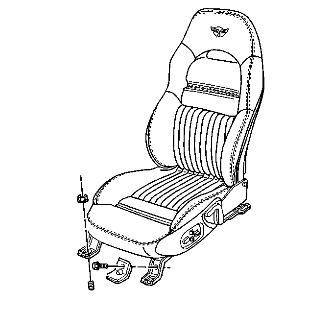
- Remove the push pins and covers from the front of the adjuster
legs.
- Remove the nuts from the front of the adjuster legs.
- Position the seat forward. If the rear adjuster nuts are accessible
skip to step 9. If the seat will not move and the rear adjuster nuts are not
accessible determine if the motor or the adjuster is the cause and perform
step 7 or 8.
- If the power seat motor is inoperative and the rear adjuster nuts
are not accessible perform the following steps.
| 7.1. | Power up and raise the front of the power seat to gain access
to the forward motor bracket. |
| 7.2. | Reach under the seat and cut the tie strap attaching the front
motor bracket to the torque tube. |
| 7.3. | Bend the bracket ends inward and slide the bracket off the adjuster
transmissions. |
| 7.4. | Pull the forward motor cables from the adjusters. |
| 7.5. | Insert one end of a removed cable into a low speed drill and insert
the other end into the adjuster. |
| 7.6. | With the low speed drill move the adjuster forward, alternating
sides, until the rear adjuster nuts are exposed. |
- If the seat adjuster is
inoperative and the rear adjuster nuts are not accessible perform the following
steps:
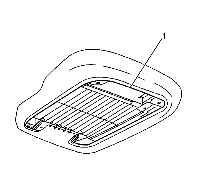
| 8.3. | Reach under the seat cushion and cut the seat cover tie string
(1) at the front center of the seat cushion. |
| 8.4. | Lift the seat cushion cover and foam to access the 4 seat cushion
to frame attaching bolts. |
| 8.5. | Remove the seat cushion to frame attaching bolts. |
| 8.6. | Cut the tie straps mounting the lumbar pump pouch and reposition
the pump and pouch up through the seat support wires. |
| 8.7. | Remove the memory seat control module from the seat. |
| 8.8. | Disconnect the seat belt harness rosebud clip (drivers seat). |
| 8.9. | Disconnect the electrical connectors. |
- Remove the nuts attaching the rear adjuster legs.
- Disconnect the seat electrical connector.
- Remove the seat and/or the adjuster.
- Transfer parts as necessary.
Installation Procedure
- Install the adjuster(s) to the seat if removed. Refer to
Front Seat Adjuster Replacement
.
- Install the seat cushion cover, if removed, Refer to
Seat Cushion Trim Cover and Pad Replacement
.
Notice: Use the correct fastener in the correct location. Replacement fasteners
must be the correct part number for that application. Fasteners requiring
replacement or fasteners requiring the use of thread locking compound or sealant
are identified in the service procedure. Do not use paints, lubricants, or
corrosion inhibitors on fasteners or fastener joint surfaces unless specified.
These coatings affect fastener torque and joint clamping force and may damage
the fastener. Use the correct tightening sequence and specifications when
installing fasteners in order to avoid damage to parts and systems.
- Install the buckle
side of the seat belt, if removed.
Tighten
Tighten the seat belt buckle side mounting nut to 50 N·m
(37 lb ft).
- Install the front motor bracket, if removed.
- Install the lumbar pump, if removed.
- Position the seat forward on the adjuster(s).
- Position the seat with the adjuster on the rear studs.
- Lift the front of the seat and connect the electrical connector.
- Install the nut to the rear inboard stud (net locating
stud).
- Install the nut to the rear outboard stud.
Tighten
Tighten the adjuster mounting nuts to 50 N·m (37 lb ft).
- Move the seat rearward.
- Install the nuts to the front adjuster legs.
Tighten
Tighten the adjuster mounting nuts to 50 N·m (37 lb ft).
- Install the adjuster leg covers.
- Secure the covers with push pins.
- Remove the protective
cover and/or install the roof lift off panel, or raise the convertible top.
Driver or Passenger Seat Replacement Manual
Removal Procedure
- Protect the interior and/or
provide access for seat removal as follows:
| • | Tilt the steering wheel full up. |
| • | Remove the coupe's roof lift off panel to provide additional space
for seat removal and/or place a protective cover over the sill plate and door
trim panel. |
| • | Lower the convertible's folding top to provide additional space
for seat removal and/or place a protective cover over the sill plate and door
trim panel. |
| • | Place a protective cover over the hardtop's sill plate and door
trim panel. |
- Position the seat rearward.
- Remove the push pins and covers from the front of the adjuster
legs.
- Remove the nuts from the front of the adjuster legs.
- Position the seat forward and proceed to step 7. If the seat wont move
because the adjuster is inoperative and the rear mounting nuts are not accessible
perform the following steps.
| 5.2. | Reach under the front of the seat cushion and cut the seat cushion
cover draw string at the front center of the seat. |
| 5.3. | Reposition the seat cushion cover and foam to access the 4 seat
cushion frame to adjuster attaching bolts. |
| 5.4. | Remove the seat cushion frame to adjuster bolts. |
| 5.5. | Remove the seat belt harness rosebud clip (drivers seat). |
- Remove the nuts attaching the rear adjuster legs.
- Remove the seat and/or the adjuster(s).
- Transfer parts as necessary.
Installation Procedure
- Install the adjuster(s) if removed. Refer to
Front Seat Adjuster Replacement
.
- Install the seat cushion cover if removed. Refer to
Seat Cushion Trim Cover and Pad Replacement
.
Notice: Use the correct fastener in the correct location. Replacement fasteners
must be the correct part number for that application. Fasteners requiring
replacement or fasteners requiring the use of thread locking compound or sealant
are identified in the service procedure. Do not use paints, lubricants, or
corrosion inhibitors on fasteners or fastener joint surfaces unless specified.
These coatings affect fastener torque and joint clamping force and may damage
the fastener. Use the correct tightening sequence and specifications when
installing fasteners in order to avoid damage to parts and systems.
- Install the buckle
side of the seat belt to the adjuster, if removed.
Tighten
Tighten the seat belt buckle side mounting nut to 50 N·m
(37 lb ft).
- Align the adjusters with their locking pawls engaged in the same
slots side to side.
- Install the seat adjuster adjustment bar.
- Position the seat forward on the seat adjusters.
- Check that the locking pawls are completely engaged in the slots.
- Position the seat adjusters on the rear floor studs.
- Connect the electrical connector (drivers side).
- Install the nut to the rear inboard stud (net locating
stud).
- Install the nut to the rear outboard stud.
Tighten
Tighten the adjuster mounting nuts to 50 N·m (37 lb ft).
- Move the seat rearward.
- Install the nuts to the front adjuster legs.
Tighten
Tighten the adjuster mounting nuts to 50 N·m (37 lb ft).
- Install the adjuster leg covers.
- Secure the covers with push pins.
- Install the roof lift
off panel if removed, or raise the convertible top if lowered.
- Remove any protective covering.
