Removal Procedure
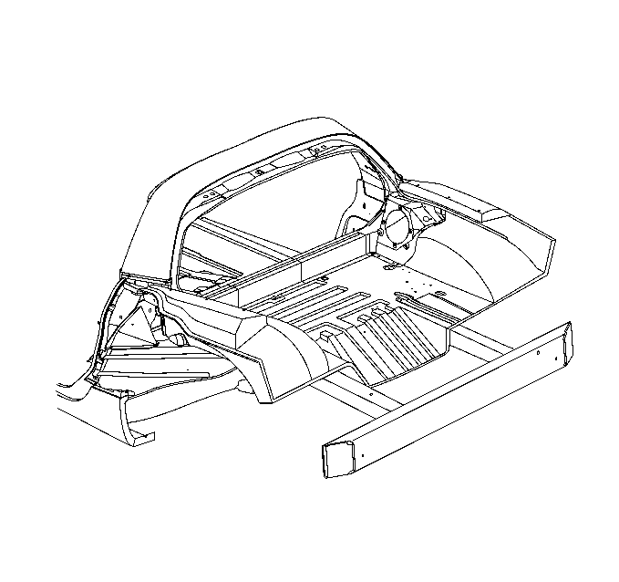
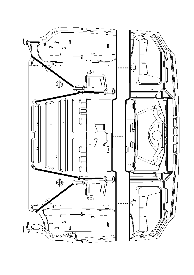
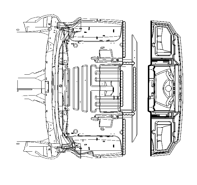
Important: The Rear Compartment Panel is manufactured with section lines to indicate the proper sectioning location of the service part. Check all the bonding areas of the Rear Compartment Panel (tub). If adhesive is cracked or broken loose from the rails or the tub, complete tub replacement is recommended.

- Disable the SIR system. Refer to SIR Disabling and Enabling in SIR.
- Disconnect the negative battery cable. Refer to Battery Negative Cable Disconnection and Connection in Engine Electrical.
- Visually inspect and repair as much of the damage as possible to specifications using three-dimensional measuring procedures. Refer to Dimensions - Body or to Measurements - Underbody .
- Remove all panels, components, and interior trim located in the rear compartment. Save any and all brackets, mounting studs, and accessories for transfer to the new rear compartment panel.
- Remove both rear quarter panels and rear compartment panel frame (rear surround).
- Identify the section line etched in the floor of the rear compartment panel.
- Remove or reposition components on the bottom side of the tub to avoid damage where sectioning procedures are being performed.
- Cut along the section line and remove the damaged panel.
Caution: Refer to Approved Equipment for Collision Repair Caution in the Preface section.
Important: Ensure that the fuel inlet is sealed before proceeding with repair procedure.

Important: The etched line is in the floor only, the line must be continued straight up both side-walls of the tub to complete the cuts.
Important: Take care not to damage the frame rails when sectioning the rear compartment panel.
Installation Procedure
- Remove all remaining adhesive, and scuff all bonding surfaces to ensure proper adhesion.
- Clean and prepare all bonding surfaces prior to SMC panel installation. Refer to Plastic Panels in Plastic Panel Information and Repair.
- Prime all bare metal surfaces with an approved anti-corrosion primer. Do not top-coat any bonding surface. Refer to Basecoat/Clearcoat Paint Systems in Paint and Coating.
- Cut the replacement rear compartment panel along the section line to create service part.
- Create 50 mm (2 in) wide backing plates to be installed along the bottom side of the section joint.
- Apply structural adhesive GM P/N 89020330 (Canadian P/N 8902332) to the backing plate strips and secure along the section joint using screws.
- Remove excess adhesive from the service part mounting area.
- Temporarily install the modified service panel and check for proper fit and alignment
- Remove service part.
- Apply structural adhesive GM P/N 89020330 (Canadian P/N 8902332) to the extended portion of the mating flange created from the backing strips, and to the frame rails, and rear bumper impact bar as necessary.
- Install the modified service part and press down firmly to wet-out the adhesive.
- Use two close-end rivets in areas indicated along the bond line to hold the tub to the rails while adhesive cures.
- Allow to cure according to adhesive manufacturer recommendations.
- After structural adhesive is fully cured, bevel butt-joint edges to prep for reinforcement and refinishing of the interior joint.
- Apply structural adhesive GM P/N 89020330 (Canadian P/N 8902332) to the entire joint area extending across the cut lines and across the backer, using tacky mesh tape or an equivalent reinforcement matting. Allow to cure as necessary.
- Prepare the repair areas as necessary to resemble OEM appearance.
- Refinish repair areas. Do not combine paint systems. Always refer to paint manufacturers recommendations. Refer to Basecoat/Clearcoat Paint Systems in Paint and Coating.
- Install all related panels and components.
- Connect the negative battery cable. Refer to Battery Negative Cable Disconnection and Connection in Engine Electrical.
- Enable the SIR system. Refer to SIR Disabling and Enabling in SIR.


Important: Use fasteners no longer than 20 mm (¾ in) in length.
