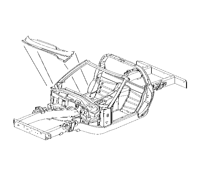
For 1990-2009 cars only
Tools Required
J 42058 Frame Adapter Clamp
Removal Procedure
- Disable the SIR system. Refer to SIR Disabling and Enabling in SIR.
- Disconnect the negative battery cable. Refer to Battery Negative Cable Disconnection and Connection in Engine Electrical.
- Remove the following panels and components to gain access to the windshield assembly:
- Visually inspect for damage to the frame rails or wheelhouse mounting areas.
- Repair as much of the damage as possible to specifications using three-dimensional measuring procedures. Use J 42058 if pulling and straightening of the vehicle are required. Refer to Dimensions - Body or to Measurements - Underbody .
- Remove and relocate wiring as necessary to avoid damage.
- Drill out the close-end rivets securing the upper plenum to the windshield frame.
- Apply heat to the upper plenum side of the bond area.
- Pry up on the panel to remove it.
- Apply heat and pry as necessary to break the windshield frame loose from the lower plenum.
- From inside the vehicle, remove all hardware attaching the instrument panel supports to the windshield frame assembly.
- Remove bolts attaching cross-car brace.
- Heat and break loose adhesive bonds.
- Remove brace from vehicle.
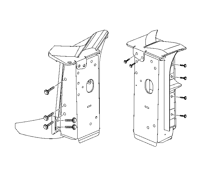
- Remove bolts attaching windshield frame to the front hinge pillars.
- Remove damaged windshield frame.
Caution: Refer to Approved Equipment for Collision Repair Caution in the Preface section.
Notice: When replacing panels that involve servicing stationary glass, refer to GM Service Bulletin no. 43-9-48 before performing any priming or refinishing.
| • | Front fenders |
| • | Front wheelhouses |
| • | Windshield |
| • | Instrument panel assembly |
Important: Use care not to damage the plenums. If they are damaged during the removal process, they should be replaced.


Installation Procedure
- Remove all remaining adhesive.
- Scuff all bonding surfaces to ensure proper adhesion.
- Clean and prepare all bonding surfaces prior to Sheet Moulded Compound (SMC) panel installation. Refer to Plastic Panels in Plastic Panel Information and Repair.
- Prime all bare metal surfaces with PPGs DP90, or an equivalent epoxy anti-corrosion primer. Do not top-coat any bonding surface. Refer to Basecoat/Clearcoat Paint Systems in Paint and Coating.
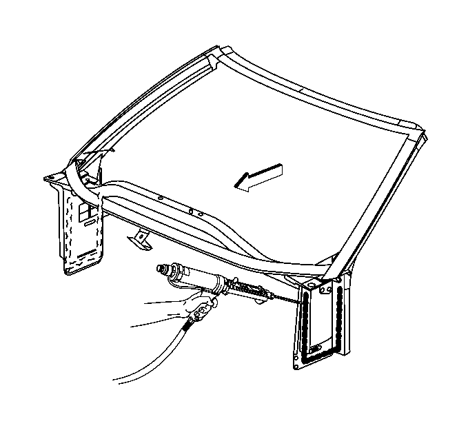
- Apply a bead of structural adhesive GM P/N 89020330 (Canadian P/N 8902332) to the bonding surfaces of the new windshield frame and install.
- Save any and all brackets, mounting studs, and accessories for transfer to the new rear compartment panel.
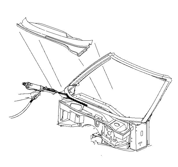
- Apply a bead of structural adhesive GM P/N 89020330 (Canadian P/N 8902332) to attach lower plenum to windshield frame. Drill holes and use close-end rivets (GM P/N 9418420, or equivalent) to hold plenum secure while adhesive cures.
- Apply a bead of structural adhesive GM P/N 89020330 (Canadian P/N 8902332) to the area that the cross-car brace bonds to the center tunnel assembly, and install brace and bolt into place.
- Attach all instrument panel supports to the windshield frame assembly service part.
- Apply a bead of structural adhesive GM P/N 89020330 (Canadian P/N 8902332) to the upper plenum and install using close-end rivets in factory locations, to hold in place while adhesive cures.
- Prime bare metal areas with an approved anti-corrosion primer. Refer to Basecoat/Clearcoat Paint Systems in Paint and Coating.
- Install all related panels and components.
- Connect the negative battery cable. Refer to Battery Negative Cable Disconnection and Connection in Engine Electrical.
- Enable the SIR system. Refer to SIR Disabling and Enabling in SIR.


Important: Do not top coat any bonding surfaces.
