For 1990-2009 cars only
Removal Procedure
Important: When servicing the right front floor panel, the bonded and bolted electrical component mounting brackets must be removed. Remove or reposition electrical components and wiring harness as necessary to avoid damage.
- Disable the SIR system. Refer to SIR Disabling and Enabling in SIR.
- Disconnect the negative battery cable. Refer to Battery Negative Cable Disconnection and Connection in Engine Electrical.
- Remove the seat and carpeting to gain access to the floor panel.
- Visually inspect for damage to the frame rail and seat mounting brace. Repair as much of the damage as possible to specifications using three-dimensional measuring procedures. Refer to Dimensions - Body or to Measurements - Underbody .
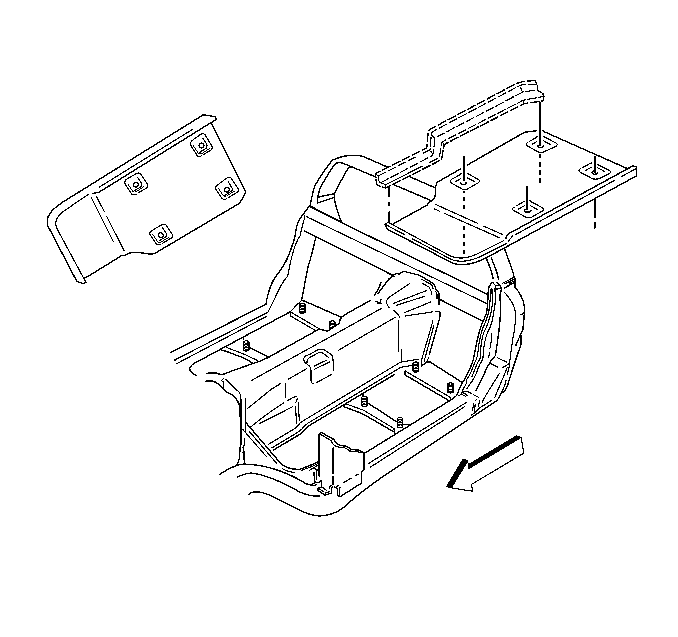
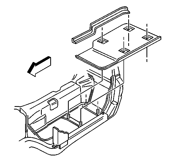
- Remove the side reinforcement bonded to the floor panel and the frame rail.
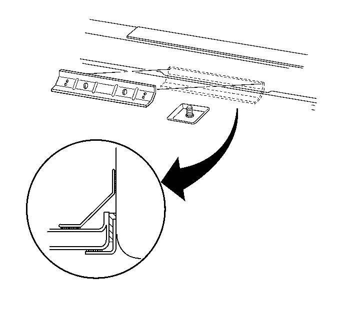
- Remove the side reinforcement bonded to the floor panel and the tunnel area.
- Apply upward force and heat simultaneously to the floor panel as necessary to detach adhesive.
- Remove damaged floor panel, save wiring harness clips (3 per side) for transfer to service floor panel.
Caution: Refer to Approved Equipment for Collision Repair Caution in the Preface section.
Important: Use care when removing the reinforcement. If it is damaged during the removal process replacement will be necessary.


Installation Procedure
- Remove all original adhesive using suitable tool.
- Scuff all bonding surfaces to ensure proper adhesion.
- Clean and prepare all bonding surfaces prior to Sheet Moulded Compound (SMC) panel installation. Refer to Plastic Panels in Plastic Panel Information and Repair.
- Prime bare metal areas with an equivalent epoxy anti-corrosion primer. Do not top-coat any bonding surface. Refer to Basecoat/Clearcoat Paint Systems in Paint and Coating.
- Temporarily position the service panel and check for proper fit, making sure the perimeter of the floor panel and the seat mount cross-brace fit flush.
- Remove the service panel.
- After primer is fully cured, apply structural adhesive GM P/N 89020330 (Canadian P/N 8902332) to the mating flanges as necessary. Keep adhesive away from seat studs to minimize squeeze out.
- Install service floor panel. Apply even pressure to all bonding surfaces to ensure the floor panel fits flush and level.
- Apply structural adhesive GM P/N 89020330 (Canadian P/N 8902332) to the new floor panel support bracket.
- Install the brace to attach floor panel to tunnel.
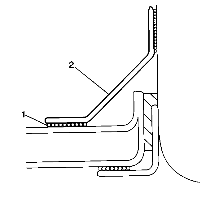
- Apply structural adhesive GM P/N 89020330 (Canadian P/N 8902332) (1) to the new floor panel brace (2) and install the brace.
- Apply pressure evenly for uniform adhesive wet-out.
- Apply structural adhesive GM P/N 89020330 (Canadian P/N 8902332) to wiring harness clips, and install at the etched indicators on the service panel by pressing firmly into place.
- Temporarily install the seat mounting nuts to wet-out the adhesive at the cross brace.
- Smooth adhesive squeeze-out around perimeter of floor panel from underside of vehicle to form a consistent, leak-proof seal.
- Apply constant firm pressure in the toe-pan area until the adhesive is fully cured.
- After the adhesive is fully cured, remove the seat mounting nuts.
- Finish and feather-edge the repair areas as necessary to resemble OEM.
- Prime the body with suitable primer. Refer to Basecoat/Clearcoat Paint Systems in Paint and Coating.
- Apply sealers and anti-corrosion materials as necessary. Refer to Anti-Corrosion Treatment and Repair in Paint and Coatings.
- Apply top-coat over all primed areas. Refer to paint manufacturer's recommendations. Do not combine paint systems. Refer to Basecoat/Clearcoat Paint Systems in Paint and Coating.
- Install all related panels and components.
- Connect the negative battery cable. Refer to Battery Negative Cable Disconnection and Connection in Engine Electrical.
- Enable the SIR system. Refer to SIR Disabling and Enabling in SIR.


