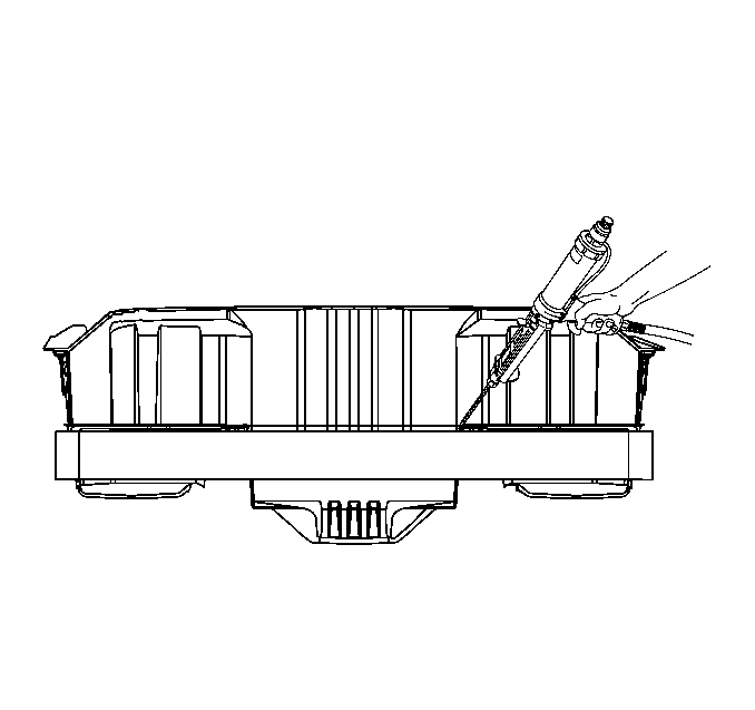
Tools Required
J 42058 Frame Adapter Clamp
Removal Procedure
- Disable the SIR system. Refer to SIR Disabling and Enabling in SIR.
- Disconnect the negative battery cable. Refer to Battery Negative Cable Disconnection and Connection in Engine Electrical.
- Remove all panels and components to gain access to the rear impact bar. This includes the following components:
- Visually inspect and repair as much of the damage as possible to specifications using 3-dimensional measuring procedures. Use J 42058 if pulling and straightening of the vehicle are required. Refer to Dimensions - Body or to Measurements - Underbody .
- Remove or reposition wiring as necessary to avoid being damaged.
- Using a die grinder or equivalent, cut the Metal Insert Gas (MIG) welds attaching the rear impact bar to the frame rails.
- Cut the welds around the perimeter of the frame rail (fishmouth) ends.
- Cut the welds favoring the impact bar side of the joint. Do not cut into the frame rails.
- To gain access to the inner rail welds, modify the rear wall of the SMC rear compartment panel in the following manner:
- The windows provide access to inner MIG welds attaching the impact bar to the rails.
- Cut the remaining welds around the perimeter of the impact bar, favoring the impact bar side of the joint.
- If necessary, apply heat, then pry apart to separate the impact bar from rear panel.
- With the rear bumper impact bar removed, repair any cracks in the SMC from outside the vehicle.
Caution: Refer to Approved Equipment for Collision Repair Caution in the Preface section.
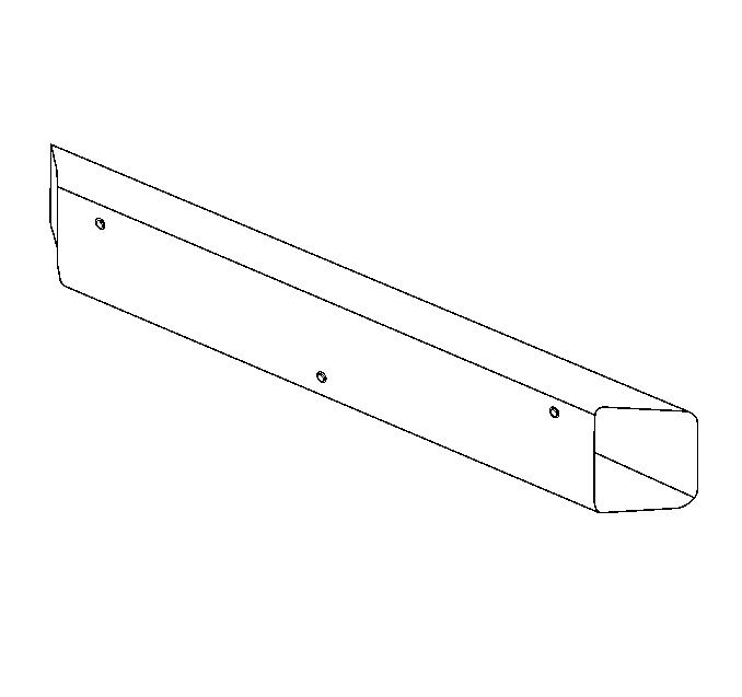
Important: Save any and all brackets, mounting studs, and accessories for transfer to the new rear compartment panel.
| • | Rear bumper cover |
| • | Energy absorber |
| • | Mufflers |
| 3.1. | Disconnect exhaust at the bolted joint just forward of the rear axle. |
| 3.2. | From inside the vehicle remove trim panels. |
| 3.3. | Pull back the carpeting inside the rear compartment area. |
Notice: The frame rails and bumper impact bars must be serviced as required, and returned to three-dimensional coordinates before any SMC repairs are attempted.
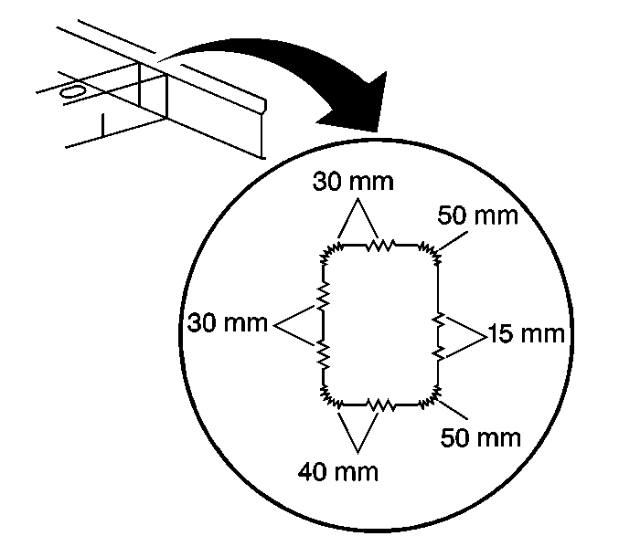
Notice: Do not cut the rails when cutting windows in the rear compartment panel.
Important: The top and bottom welded edges, as well as the outer rail welds, are accessible from outside the vehicle.
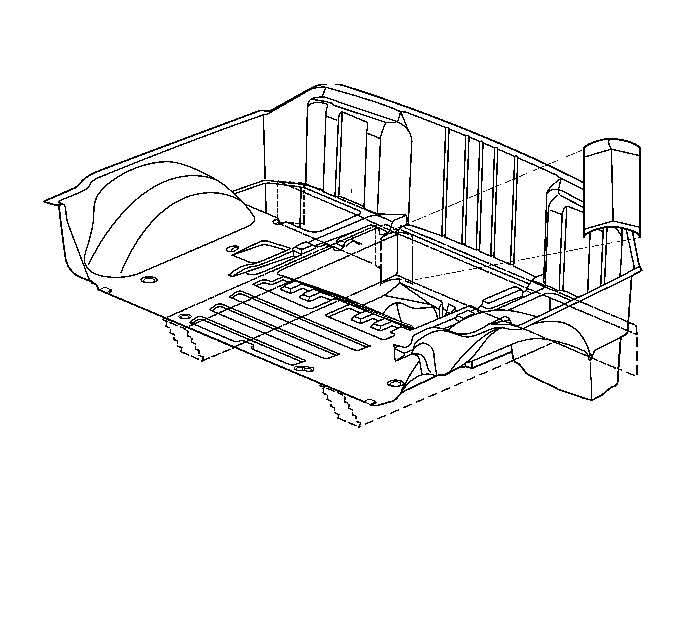
| • | Save the cutouts for re-installation. |
| • | From inside the vehicle locate, mark, and cut out windows in the rear compartment panel. |
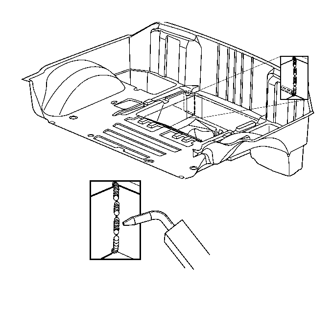
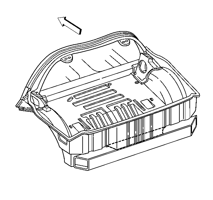
Important: Do not install the windows in rear compartment yet, welding access is necessary for installing the replacement impact bar.
Installation Procedure
- Straighten and deburr the rail ends as necessary to allow the service bumper impact bar to fit the rail ends properly.
- Remove any adhesive which is cracked or broken loose from the rails or the rear compartment panel.
- Remove the primer from the areas to be MIG welded by sanding with 80-grit paper on a Dual-Action (DA) sander. Do not use a grinder to remove the primer.
- Prepare all bare metal surfaces and apply 3M weld-thur coating P/N 05916 or equivalent as necessary. Be sure to apply primer to the inside of the fishmouth area also.
- Position the bumper impact bar using three-dimensional measuring equipment and weld accordingly.
- Clean and prepare all welded surfaces using 3M's Scotch-Brite Clean-N-Strip Discs (disc P/N 07460, mandrel P/N 07491), or equivalent.
- From outside the vehicle, apply 50 mm (2 in) wide tape over the windows cut in the rear compartment panel.
- Apply structural adhesive GM P/N 89020330 or GM P/N (Canada 8902332), to the inside of the tape backer.
- Install the previously cut-out pieces in their original locations.
- Apply structural adhesive GM P/N 89020330 or GM P/N (Canada 8902332), to the inside of the tape backer to the entire repair area extending across the cut lines, using tacky mesh tape or an equivalent reinforcement matting.
- Scuff all bonding surfaces to ensure proper adhesion.
- Clean and prepare all bonding surfaces as necessary.
- Apply a bead of structural adhesive GM P/N 89020330 or GM P/N (Canada 8902332), to bond the impact bar to the rear compartment. This is a structural bond, and care must be used to ensure that the adhesive fills the gap adequately.
- Finish and feather-edge the repair areas as necessary to resemble OEM.
- Apply appropriate sealers. Refer to Anti-Corrosion Treatment and Repair in Paint and Coating.
- Apply top-coat over all repaired areas. Refer to Basecoat/Clearcoat Paint Systems in Paint and Coating.
- Install all related panels and components.
- Connect the negative battery cable. Refer to Battery Negative Cable Disconnection and Connection in Engine Electrical.
- Enable the SIR system. Refer to SIR Disabling and Enabling in SIR.

| 5.1. | Stitch weld around the fishmouth joint. |
| 5.2. | Make 40 mm (1 in) MIG welds along the top, bottom, and outer sides of the joint. This will create a solid weld joint with minimal heat distortion. |
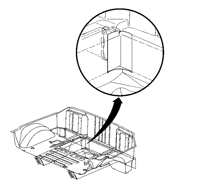
Notice: Do not top coat the top surface of the impact bar where it is to be bonded to the rear compartment panel. The bonding area must remain a primer-only surface.
| • | Apply enough structural adhesive GM P/N 89020330 or GM P/N (Canada 8902332), to fully wet out reinforcement matting. |
| • | Allow to cure as necessary. |
