For 1990-2009 cars only
Tools Required
J 42058 Frame Adapter Clamp
Removal Procedure
- Disable the SIR system. Refer to SIR Disabling and Enabling in SIR.
- Disconnect the negative battery cable. Refer to Battery Negative Cable Disconnection and Connection in Engine Electrical.
- Visually inspect for damage to the frame rails or wheelhouse mounting areas. Repair as much of the damage as possible to specifications using three-dimensional measuring procedures. Use J 42058 if vehicle pulling and straightening are required. Refer to Dimensions - Body or to Measurements - Underbody .
- Remove all panels and components to gain access to door side frame. The door side frame can be removed if the quarter panel is loosened from it. This may include removal of the following components:
- Remove latch striker closeout cover and striker.
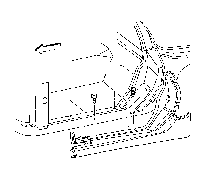
- Remove the trim screws that attach the side door frame panel to the rail. These screws must be re-installed to secure the service panel in place until the adhesive cures.
- Use caution along the underside of the vehicle when applying heat not to de-bond the floor panels from the frame rail.
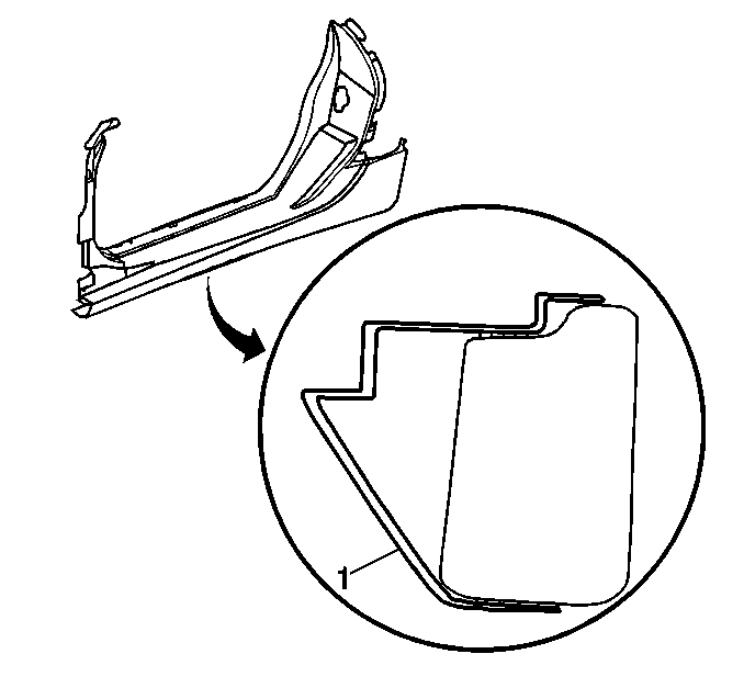
- Apply heat and pry to break bond along area (1).
Caution: Refer to Approved Equipment for Collision Repair Caution in the Preface section.
Notice: The frame rails and bumper impact bars must be serviced as required, and returned to three-dimensional coordinates before any SMC repairs are attempted.
| • | Door |
| • | Quarter panel |
| • | Quarter inner splash shield |
Important: Ensure that the fuel inlet is sealed before proceeding with repair procedure.

Installation Procedure
- Remove all remaining adhesive, and scuff all bonding surfaces to ensure proper adhesion.
- Clean and prepare all bonding surfaces prior to SMC panel installation. Refer to Plastic Panels in Plastic Panel Information and Repair.
- Prime bare metal areas with an equivalent epoxy anti-corrosion primer. Do not top-coat any bonding surface. Refer to Basecoat/Clearcoat Paint Systems in Paint and Coating.
- Temporarily fit the side door opening assembly to ensure proper fit and alignment with adjacent panels.
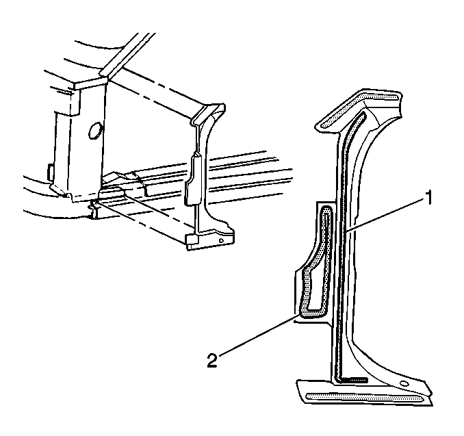
- Remove panel assembly and apply structural adhesive GM P/N 89020330 (Canadian P/N 8902332) (1) to the front body hinge pillar and top surface of rail (2) and to all areas originally bonded, except for bottom side of rail.
- The bead should be 10 mm (13/32 in) diameter.
- This area is bonded after the side door opening assembly is installed.
- Install assembly using original screws in factory locations. The screws are necessary to secure the service part until the adhesive cures.
- Apply structural adhesive GM P/N 89020330 (Canadian P/N 8902332) to inner edge of rocker and clamp in place until adhesive cures. Standoffs in part must fit flush against bottom of rail.
- Remove excess adhesive squeeze-out and allow to cure.
- Prime bare metal areas with an equivalent epoxy anti-corrosion primer. Do not combine paint systems. Always refer to paint manufacturer's recommendations. Refer to Basecoat/Clearcoat Paint Systems in Paint and Coating.
- Install all related panels and components.
- Connect the negative battery cable. Refer to Battery Negative Cable Disconnection and Connection in Engine Electrical.
- Enable the SIR system. Refer to SIR Disabling and Enabling in SIR.


Important: Ensure that the foam seal on the front body hinge pillar portion of the side door opening panel makes contact with the front hinge pillar.
Important: Use only approved adhesives. Refer to Rigid Plastic Part Repair Materials in Plastic Panel Information and Repair.
