For 1990-2009 cars only
Tools Required
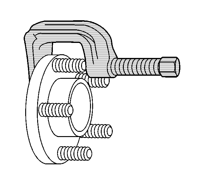
J 43631 Ball Joint Separator
Removal Procedure
- Raise and support the vehicle. Refer to Lifting and Jacking the Vehicle in General Information.
- Remove the tire and wheel assembly. Refer to Tire and Wheel Removal and Installation in Tires and Wheels.
- Remove the rear wheel hub/speed sensor assembly from the suspension knuckle. Refer to Rear Wheel Bearing and Hub Replacement .
- Install J 43631 onto the wheel hub and stud.
- Turn the forcing screw in until the stud is pushed out of the wheel hub.

Installation Procedure
- Place a new stud in the wheel hub.
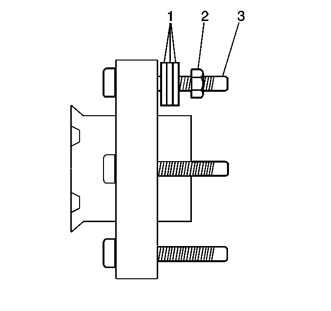
- Place some washers (1) onto the wheel stud (3).
- With the flat side of a wheel nut against the washers, tighten the wheel nut until the wheel stud head seats against the wheel hub flange.
- Remove the wheel nut and washers.
- Install the rear wheel hub/speed sensor assembly into the suspension knuckle. Refer to Rear Wheel Bearing and Hub Replacement .
- Install the tire and wheel assembly. Refer to Tire and Wheel Removal and Installation in Tires and Wheels.
- Lower the vehicle.

Important: Make sure that the wheel stud is fully seated against the wheel hub flange.
