SMU - Revised Steering Column Turn Signal Cancel Cam and Steering Shaft Upper (Manual and Telescoping) Procedure

| Subject: | Revised Steering Column Turn Signal Cancel Cam and Steering Shaft Upper Bearing Spring Replacement (Manual and Telescoping) Procedure |
| Models: | 1997-2004 Chevrolet Corvette -- with Manual Transmission |
| 1997-2000 Chevrolet Corvette -- with Automatic Transmission (Export Only) |
| 2001-2004 Chevrolet Corvette -- with Automatic Transmission (Europe Only) |
| Attention: | This bulletin applies to authorized Chevrolet Corvette Dealers only. |
Important: The revised procedure should be completed ONLY if the vehicle has had Product Safety Recall 04006B (Electronic Column Lock System) completed.
This bulletin is being issued to revise the removal and replacement procedure for the Steering Column Turn Signal Cancel Cam and Steering Shaft Upper Spring Replacement (Manual and Telescoping) procedure in the Steering Wheel and Column sub-section of the Service Manual. Please replace the current information in the Service Manual with the following information.
The following information has been updated within SI. If you are using a paper version of this Service Manual, please make a reference to this bulletin on the affected page.
Upon reinstallation of the steering column shaft lock shield, it is recommended to electronically function test the operation of the ECL (Electronic Column Lock) to ensure the proper installation of the shaft lock shield. The test below will determine if the shaft lock shield is correctly installed. If the ECL pin contact the shaft lock shield, repeat the Turn Signal Cancel Cam and Steering Shaft Upper Bearing Spring Replacement (Telescoping and Manual) Procedure.
The required functional test may require a special tool that was shipped to all Corvette Dealers. Depending on the model year of the vehicle, Special Tool EL47728 will be needed to complete the repair. Refer to the chart below to determine the correct functional test for the vehicle you are working on.
Models | Functional Test | |
|---|---|---|
Tech 2 | Tech 2 w/EL47728 | |
1997 All Manual & Export Automatic | ||
All |
| X |
1998 All Manual & Export Automatic | ||
Built through 5/25/98 |
| X |
Built on or after 5/26/98 | X |
|
1999-2000 All Manual & Export Automatic | ||
All | X |
|
2001-2004 All Manual and European Automatics | ||
All | X |
|
Turn Signal Cancel Cam and Steering Shaft Upper Bearing Spring Replacement
| • | J 23653-SIR Steering Column Lock Plate Compressor |
| • | J 42137 Steering Column Lock Plate Compressor Adapter |
| • | EL47728 Electronic Column Lock Tester (for 1997 and 1998 model built through 5/25/98) |
Important: The function test portion of this procedure should ONLY be used on:
• 1997-2004 Corvette with a manual transmission • 1997-2004 Corvette with an automatic transmission -- export only • 2001-2004 Corvette with an automatic transmission -- European only
Important: This procedure should ONLY be used on Corvettes that have had product safety recall 04006B (Electronic Column Lock System) completed. If 04006B has not been completed, it MUST be completed first.
Removal Procedure
- Disable the SIR System. Refer to Disabling the SIR System in SIR.
- Remove the SIR coil from the steering column. Refer to Steering Wheel Inflator Module Coil Replacement in SIR.
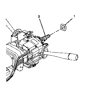
- Remove the wave washer (1) from the steering shaft assembly (2).
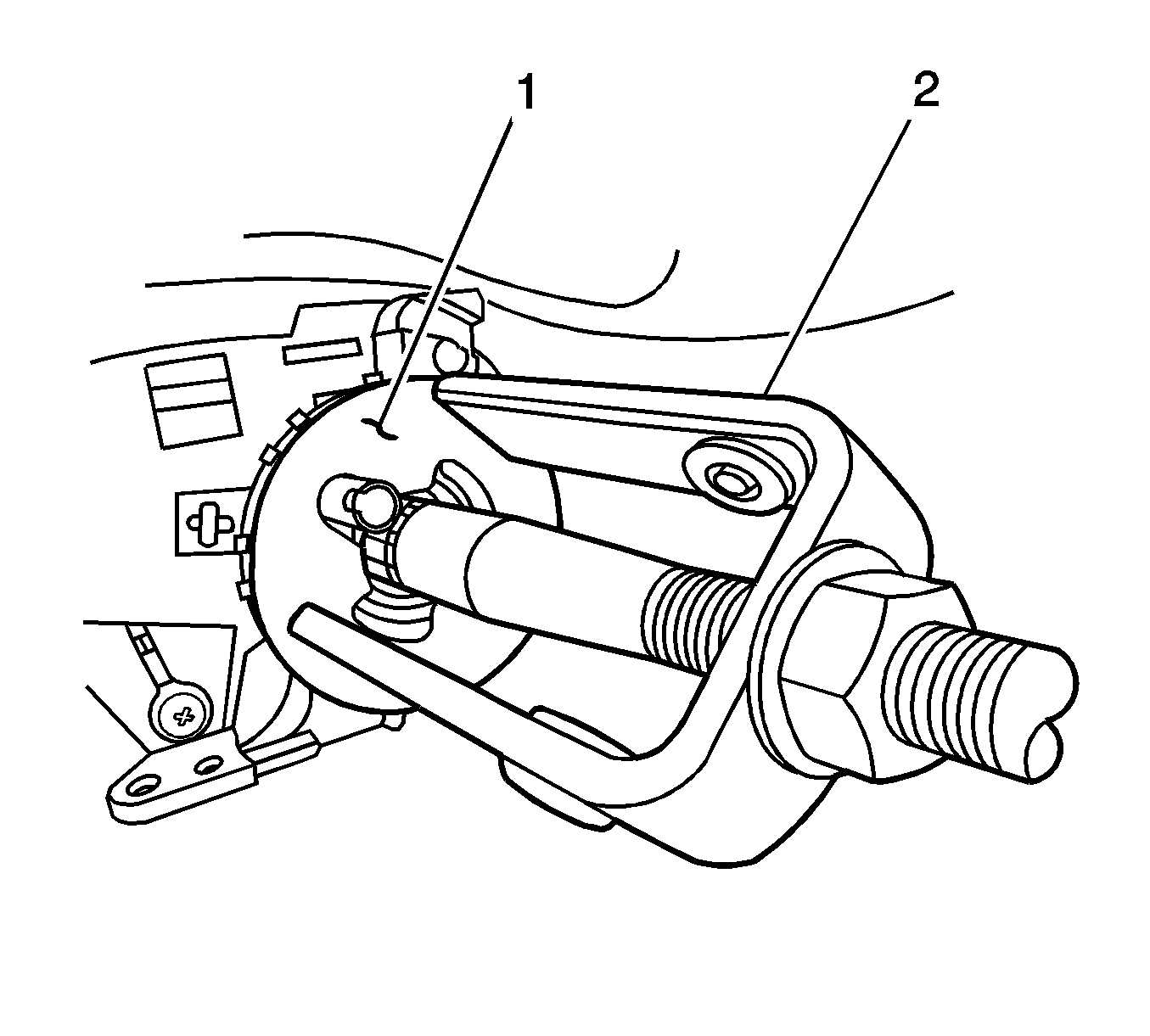
- Compress the cam orientation plate using J 23653-SIR (2) and J 42137 (1).
- Remove the bearing retainer from the steering shaft assembly.
- Remove J 23653-SIR and J 42137.
- Dispose of the bearing retainer.
- Remove the following from the steering shaft:

Caution: Refer to SIR Caution in Cautions and Notices.
Important: Let the SIR coil hang freely after removal.


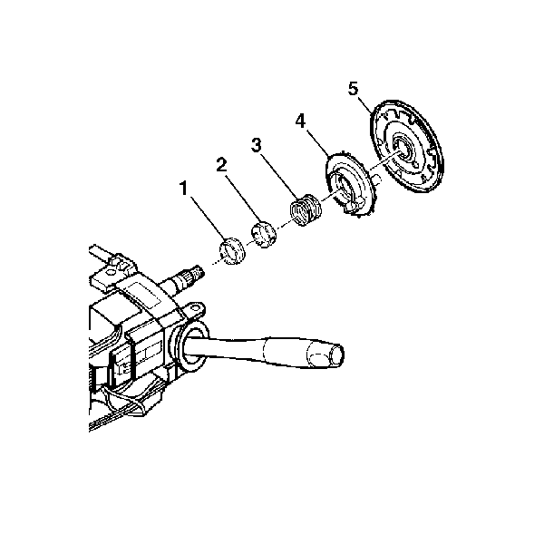
| 8.1. | Shaft lock shield (5) |
| 8.2. | Turn signal cancel cam assembly (4) |
| 8.3. | Upper bearing spring (3) |
| 8.4. | Upper bearing inner race seat (2) |
| 8.5. | Inner race (1) |
Installation Procedure
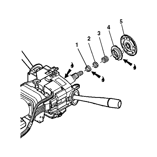
- Lubricate where indicated with synthetic grease.
- Install the following to the steering shaft:
- Install a new bearing retainer onto the steering shaft assembly.
- Compress the cam orientation plate using J 23653-SIR (2) and J 42137 (1) to install the bearing retainer.
- Remove J 23653-SIR and J 42137 from the steering shaft assembly.
- Install the wave washer (1) onto the steering shaft assembly (2). Using the procedure below, perform a functional test of the ECL using the Tech 2 and EL47728 Electronic Column Lock Tester (for 1997 and 1998 models built before 5/26/98).
- Raise the vehicle on a suitable lift so that the front wheels are off the ground by a few millimeters.
- Position the front tires/wheels in the straight-ahead position.
- Open the hood and connect a battery charger to the vehicle. Operate the charger at a Low or Medium charge rate.
- Turn the ignition to the ON position.
- Close both windows and turn off all accessories (radio, HVAC, etc.) and lighting.
- While listening carefully, slowly turn the steering wheel to the full left and then back to the full right. Then return the front tires/wheels to the straight-ahead position.
- Turn the ignition switch to the OFF position and REMOVE THE KEY.
- Verify that the steering column LOCKED and that no ECL-related messages are displayed on the Driver Information Center. It may be necessary to turn the steering wheel slightly in order for the ECL to engage in one of the openings in the lock plate.
- If the vehicle is a 1997 or 1998 built before 5/26/98, disconnect the upper pink 32-way connector (C2) and the lower green 16-way connector (C3) from the BCM. Attach the tester to the BCM and to the vehicle's wiring harness pink and green connectors.
- Connect the Tech 2 to the vehicle's DLC, power it up, and press ENTER. If necessary, refer to up-do-date Techline equipment user instructions.
- Select DIAGNOSTICS.
- Enter MODEL YEAR followed by PASSENGER CAR, followed by BODY.
- Select "Y" for the product line followed by the appropriate body style (coupe, convertible, etc.).
- Select BODY CONTROL MODULE, followed by SPECIAL FUNCTIONS, followed by OUTPUT CONTROL followed by MISCELLANEOUS TESTS.
- Select STEERING COL. LOCK FUNCTIONAL TEST.
- Open the hood and connect a battery charger to the vehicle. Operate the charger at a Low or Medium charge rate.
- Follow the on-screen instructions.
- Results of Functional Test:
- Press the EXIT button on the Tech 2 as necessary and disconnect it from the vehicle.
- Disconnect the battery charger from the vehicle and close the hood.
- If the vehicle is a 1997 or 1998 built before 5/26/98, disconnect the EL47728 from the BCM and the vehicle's wiring harness. Then reconnect the vehicle's wiring harness to the BCM. Also, reassembly the BCM area of the vehicle at this time.
- Using the Tech 2, check and erase any current and history codes that may be stored in the BCM.
- Install the SIR coil. Refer to Steering Wheel Inflator Module Coil Replacement in SIR.
- Enable the SIR system. Refer to Enabling the SIR System in SIR.

| 2.1. | Inner race (1) |
| 2.2. | Upper bearing inner race seat (2) |
| 2.3. | Upper bearing spring (3) |
| 2.4. | Turn signal cancel cam assembly (4) |
| 2.5. | Shaft lock shield (5) |

Important: The bearing retainer must be properly seated into the groove on the steering shaft.
Important: Depending on conditions that may occur during the functional test, the Tech 2 may display various messages (Sequence Number). Definitions for the different sequence messages are at the end of the functional test procedure in this bulletin.
Important: In order to perform the following procedure, your Tech 2 must be updated with software version 24.008 or later. If your Tech 2 does not have the necessary software, you will need to update it before proceeding.
Important: In order to hear a possible interference between the ECL and the lock plate in the steering column during the functional test, the area in and around the vehicle must be as quiet as possible in the next few steps.
| • | If you heard any ratcheting, ticking, scraping or other type sounds coming from the steering column, locate the source and correct before proceeding. |
| • | If you did NOT hear any ratcheting, ticking, scraping or other type sounds, continue to the next step. |
Important: The ignition key must be removed from the ignition switch in the next step.
| • | If the column did not lock, inspect for installation of a Cam Orientation Plate and the related wiring harness that are to be used only on non-export vehicle with AUTOMATIC transmissions. |
| • | Inspect for installation of aftermarket wiring/relay that override the operation of the steering column lock. |
| • | Repair the ECL system per Service Manual procedure before proceeding with this functional test. |
Important: On 1997 and 1998 models built BEFORE 5/26/98, EL47728, Electronic Column Lock Tester, must be installed in the vehicle in the next step.
Important: The test is only for vehicles with manual transmission and EXPORT vehicles with automatic transmissions. Do NOT use this test on non-export vehicles with automatic transmissions.
Important: The battery voltage must be maintained between 13.0 and 15.0 volts when performing the functional test in the next steps. Because the engine is NOT to be running during the test, a battery charger must be connected to the vehicle in the next step. The battery charger must be operated at a Low or Medium charge rate. Do NOT operate the charger on a "Fast Charge" or "HIGH" charge rate. Doing so may exceed the 15.0 volt limit for the test.
| • | If you could hear or feel any type of ratcheting, ticking or scraping sound (that wasn't heard earlier) when turning the steering wheel, the steering column lock plate, retaining ring, and steering wheel retaining nut must be replaced. Proceed to the section of bulletin 04006B titled "Lock Plate, Retaining Ring, and Nut Replacement." |
| • | If you could NOT hear or feel any type of ratcheting, ticking or scraping sound when turning the steering wheel, no further repairs are required. Proceed to the next step. |
Important: On 1997 and 1998 models built BEFORE 5/26/98, EL47728 Electronic Column Lock Tester, must be removed from the vehicle in the next step. If it is not removed, the ECL and starter will not operate with the ignition key.
Important: When using EL47728, some codes may be set in the BCM. These codes must be cleared in the next step.
Tech 2 Message Definitions
| - | Test Won't Start "Battery voltage needs to be between 13.0 and 15.0 in order to run test." Connect the battery charger to the battery and operate the charger at a Low or Medium rate. DO NOT operate the charger on High or Fast Charge. |
| - | Test Terminated Sequence 1 "Make sure steering is not side loaded." The front tires are turned tightly left or right causing the steering column to be under load and the ECL pin to bind in lock plate. To correct, turn the steering wheel so that the tires are straight ahead and restart the test. |
| - | Test Terminated Sequence 2 "Remove key from ignition switch." The test cannot run with the key in the ignition switch. To correct, remove the key and restart the test. |
| - | Test Terminated Sequence 3 Not applicable. Depending on the condition, different messages may be displayed in Sequence 3. |
| - | Test Terminated Sequence 4 "Test Terminated" or "Check for automatic transmission (non-export) steering wheel theft deterrent lock shorting harness" being installed. The harness is only for use on non-export vehicles with automatic transmissions. It is NOT for use on manual transmission vehicles. If the harness has been installed, it must be removed. If the harness is not there, replace the ECL. |
| - | Test Terminated Sequence 5 "Test Terminated". Check for the automatic transmission (non-export) steering wheel theft deterrent lock shorting harness being installed. The harness is only for use on non-export vehicles with automatic transmissions. It is NOT for use on manual transmission vehicles or EXPORT automatic transmission vehicles. if the harness has been installed, it must be removed. If the harness is not there, replace the ECL. |
