Removal Procedure
- Remove the fuel rail cover.
- Remove the generator. Refer to Generator Replacement in Engine Electrical.
- Raise and suitably support the vehicle. Refer to Lifting and Jacking the Vehicle in General Information.
- Remove the exhaust manifold nuts.
- Remove the connector position assurance (CPA) lock.
- Disconnect the oxygen sensor electrical connector.
- Remove the oxygen sensor connector clip at the body.
- Remove the oxygen sensor.
- Lower the vehicle.
- Remove the hose clamp at the secondary air injection (AIR) pipe.
- Remove the AIR hose from the AIR pipe.
- Remove the hose clamps at the right and left check valves.
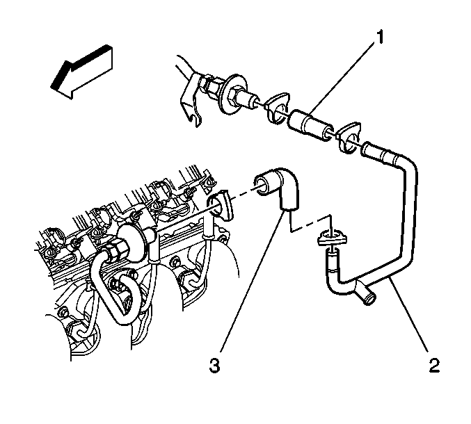
- Remove the AIR injection pipe hose (1) from the right check valve.
- Remove the AIR injection pipe hose (3) from the left check valve.
- Remove the AIR pipe (2).
- Remove the AIR pipe bolts.
- Remove the AIR pipe and gasket. Discard the old gasket
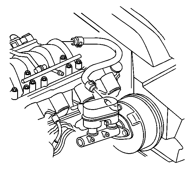
- Remove the brake booster vacuum hose from the brake booster.
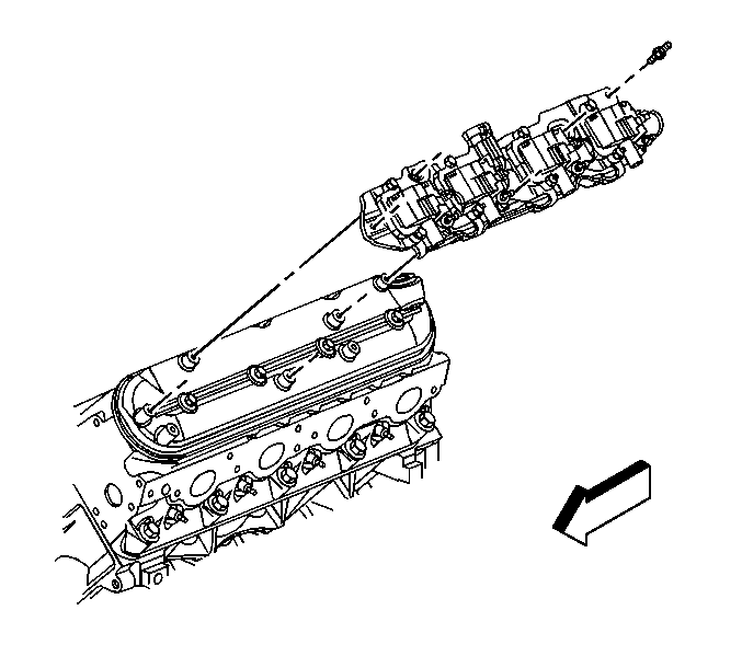
- Remove the ignition coil bracket studs.
- Remove the ignition coil bracket.
- Remove the spark plugs. Refer to Spark Plug Replacement in Engine Controls - 5.7 L.
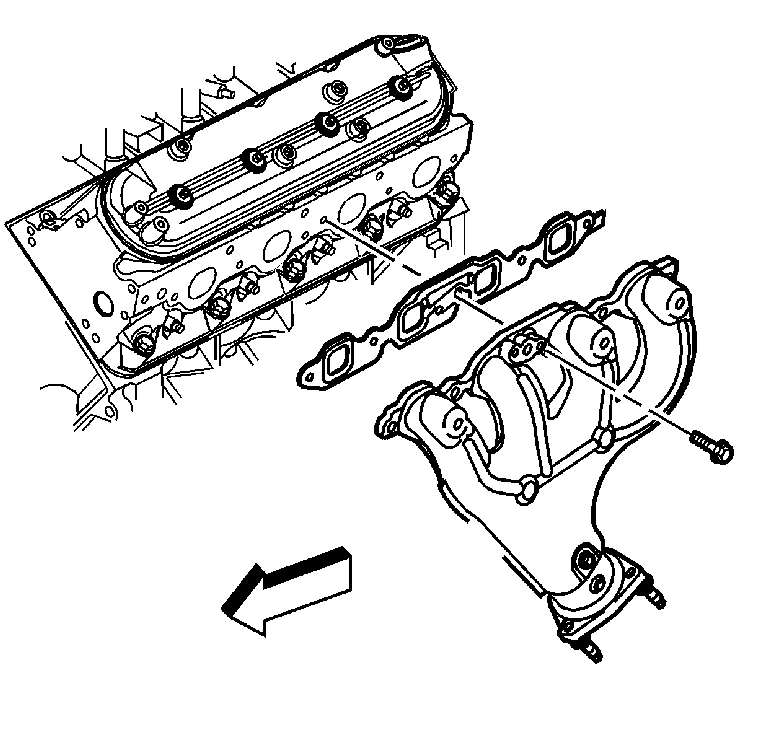
- Remove the exhaust manifold bolts.
- Remove the exhaust manifold, and old gasket. Discard the gasket.
- If necessary, remove the exhaust manifold heat shield bolts and shield.
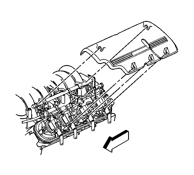
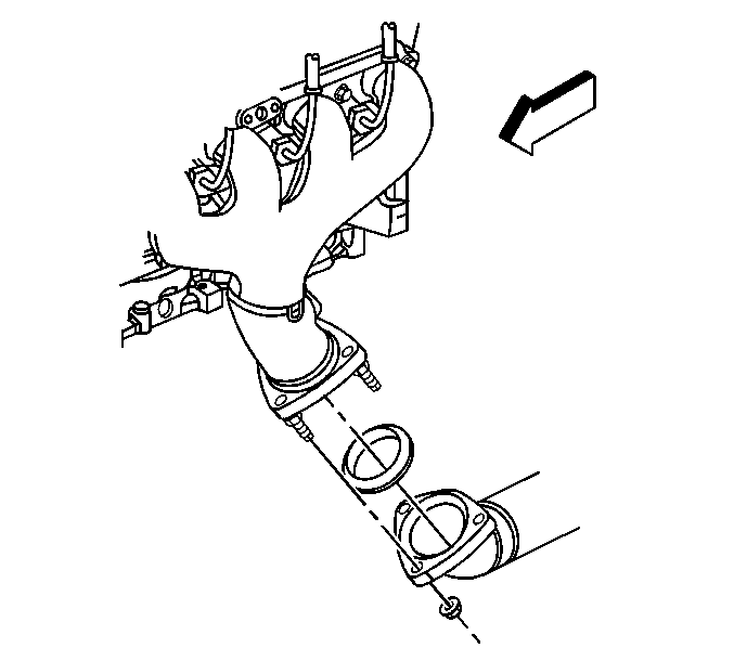
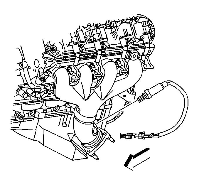
Notice: Handle the oxygen sensors carefully in order to prevent damage to the component. Keep the electrical connector and the exhaust inlet end free of contaminants. Do not use cleaning solvents on the sensor. Do not drop or mishandle the sensor.
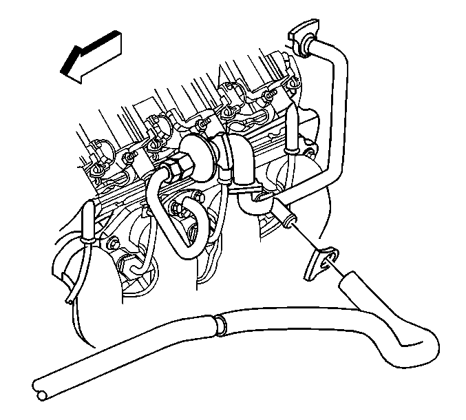
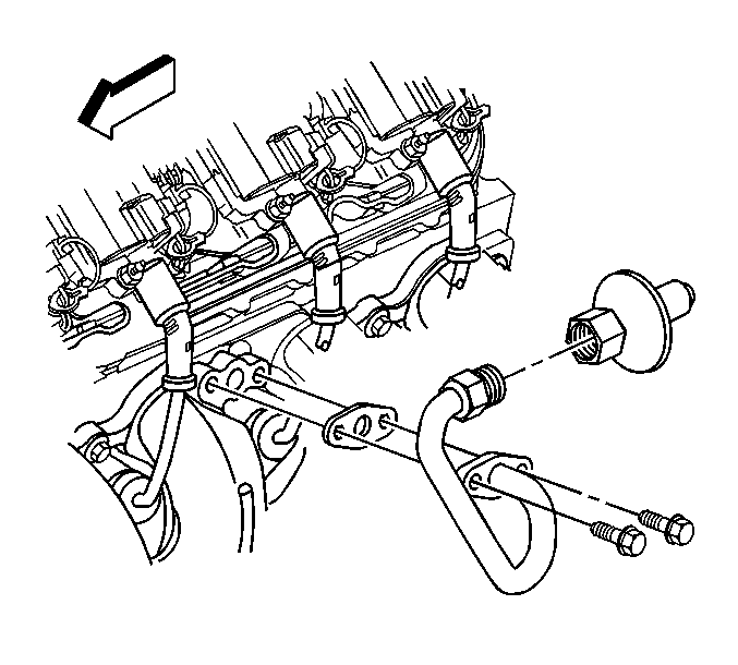
Important: Do not remove the check valve from the AIR pipe unless valve service is required.
Installation Procedure
Important: Tighten the exhaust manifold bolts as specified in the service procedure. Improperly installed and/or leaking exhaust manifold gaskets may effect vehicle emissions and/or On-Board Diagnostics (OBD) II system performance.
The cylinder head exhaust manifold bolt hole threads must be cleaned and free of debris or threadlocking material.- If necessary, install the exhaust manifold heat shield and bolts.
- Apply a 5 mm (0.2 in) wide band of threadlock GM P/N 12345493 (Canadian P/N 10953489), or equivalent to the threads of the exhaust manifold bolts.
- Position the exhaust manifold and a NEW gasket into place.
- Install the exhaust manifold bolts.
- Tighten the exhaust manifold bolts a first pass to 15 N·m (11 lb ft). Tighten the exhaust manifold bolts beginning with the center two bolts. Alternate from side-to-side, working toward the outside bolts.
- Tighten the exhaust manifold bolts a final pass to 25 N·m (18 lb ft). Tighten the exhaust manifold bolts beginning with the center two bolts. Alternate from side-to-side, working toward the outside bolts.
- Bend over the exposed edge of the exhaust manifold gasket at the rear of the cylinder head.
- Install the spark plugs. Refer to Spark Plug Replacement in Engine Controls - 5.7 L.
- Place the ignition coil bracket into place.
- Apply threadlock GM P/N 12345382 (Canadian P/N 10953489), or equivalent to the threads of the coil bracket studs.
- Install the ignition coil bracket studs.
- Install the brake booster vacuum hose to the brake booster.
- Install the AIR pipe (with check valve) and a NEW gasket.
- Install the AIR pipe bolts.
- Install the AIR pipe (2).
- Install the AIR injection pipe hose (3) to the left check valve.
- Install the AIR injection pipe hose (1) to the right check valve.
- Install the hose clamps at the right and left check valves.
- Install the AIR hose to the AIR pipe.
- Install the hose clamp at the AIR pipe.
- Raise the vehicle.
- Apply anti-sieze compound GM P/N 12377953 or equivalent to the threads of the oxygen sensor.
- Install the oxygen sensor.
- Install the oxygen sensor connector clip at the body.
- Connect the oxygen sensor electrical connector.
- Install the CPA lock.
- Install the exhaust manifold nuts.
- Lower the vehicle.
- Install the generator. Refer to Generator Replacement in Engine Electrical.
- Install the fuel rail cover.

Notice: Use the correct fastener in the correct location. Replacement fasteners must be the correct part number for that application. Fasteners requiring replacement or fasteners requiring the use of thread locking compound or sealant are identified in the service procedure. Do not use paints, lubricants, or corrosion inhibitors on fasteners or fastener joint surfaces unless specified. These coatings affect fastener torque and joint clamping force and may damage the fastener. Use the correct tightening sequence and specifications when installing fasteners in order to avoid damage to parts and systems.
Tighten
Tighten the exhaust manifold heat shield bolts to 9 N·m
(80 lb in).
Tighten

Tighten
Tighten the ignition coil bracket studs to 12 N·m (106 lb in).


Tighten
Tighten the AIR pipe bolts to 20 N·m (15 lb ft).


Notice: Handle the oxygen sensors carefully in order to prevent damage to the component. Keep the electrical connector and the exhaust inlet end free of contaminants. Do not use cleaning solvents on the sensor. Do not drop or mishandle the sensor.
Tighten
Tighten the oxygen sensor to 42 N·m (30 lb ft).

Tighten
Tighten the exhaust manifold nuts to 20 N·m (15 lb ft).

