Shimming Procedures Y Car
Input Shaft, Mainshaft, and Countershaft
Tools Required
- Rotate the transmission adapter plate to the vertical position.
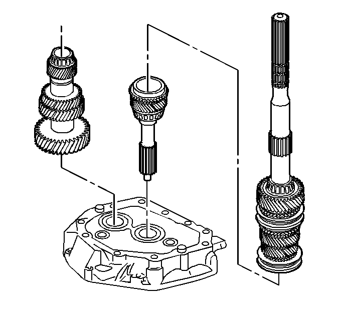
- Install the following
assemblies in order:
| 2.1. | The input shaft to the adapter plate |
| 2.2. | Align the 4th speed gear blocking ring to the input shaft. |
| 2.3. | The mainshaft assembly |
| 2.4. | The countershaft (lift up the mainshaft enough to install the
countershaft.) |
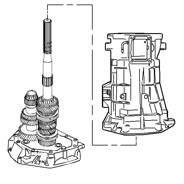
- Install the transmission
case.
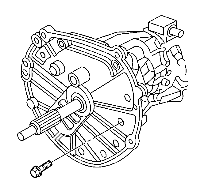
Notice: Use the correct fastener in the correct location. Replacement fasteners
must be the correct part number for that application. Fasteners requiring
replacement or fasteners requiring the use of thread locking compound or sealant
are identified in the service procedure. Do not use paints, lubricants, or
corrosion inhibitors on fasteners or fastener joint surfaces unless specified.
These coatings affect fastener torque and joint clamping force and may damage
the fastener. Use the correct tightening sequence and specifications when
installing fasteners in order to avoid damage to parts and systems.
- Install the adapter
plate to transmission case bolts.
Tighten
Tighten the bolts to 35 N·m (26 Ib ft).
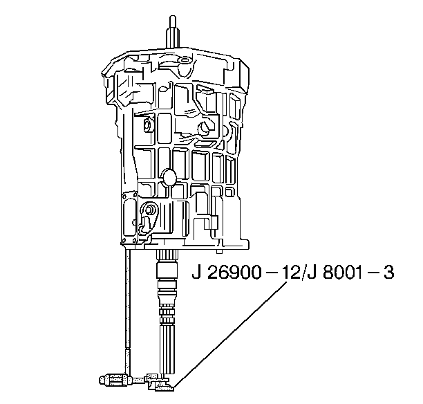
- Measure the input shaft/mainshaft
end play using the following procedure:
| 5.1. | Place the tip of the J 8001
-3 on the end of the mainshaft. |
| 5.2. | Move the input shaft up and down. |
| 5.3. | Record the measurement. |
- Select a shim to achieve 0.00-0.05 mm (0.000-0.002 in)
preload.
- Remove the J 8001
-3.
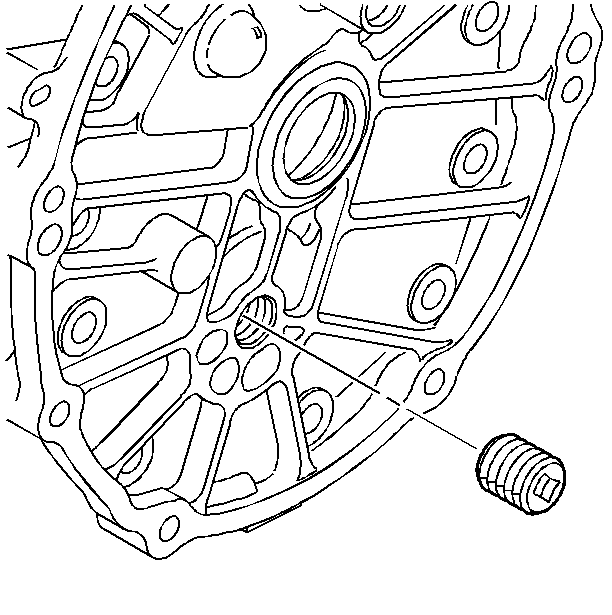
- Remove the adapter plate
plug.
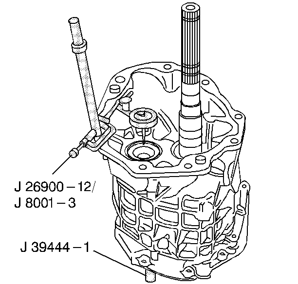
- Place the tip of the J 8001
-3 on the end of the countershaft.
- Measure the countershaft end play using the following procedure:
| 10.1. | Install the J 39444-1
through the adapter plate plug hole. Screw the J 39444-1
into the countershaft. |
| 10.2. | Move the countershaft up and down with the countershaft end play
rod J 39444-1
. |
| 10.3. | Record the measurement. |
- Select a shim to achieve 0.00-0.05 mm (0.000-0.002 in)
preload.
- Remove the J 8001
-3.
- Remove the J 39444-1
.

- Remove the adapter plate
to the transmission case bolts.

- Remove the transmission
case.

- Remove the following parts
in order:
| 16.1. | The countershaft (lift up the mainshaft enough to remove the countershaft). |
| 16.2. | The mainshaft assembly |
| 16.3. | The input shaft from the adapter plate |
| 16.4. | The input shaft bearing race |
| 16.5. | The countershaft bearing race |
Countershaft Extension
Tools Required
| • | J 39444-2 Countershaft
Extension End Play Rod |
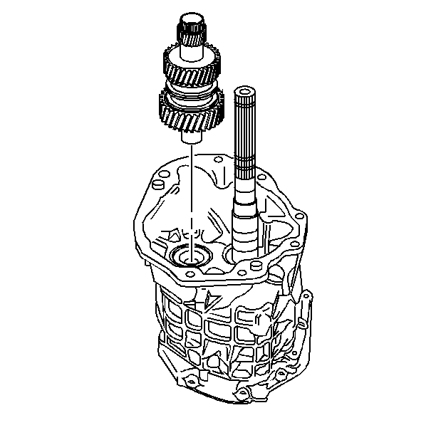
Important: The following procedure cannot be performed accurately until the countershaft
shimming procedure has been completed and the transmission has been assembled
to the point of installing the countershaft extension.
- Rotate the transmission in the horizontal position.
- Install the countershaft extension to the countershaft. Make
sure the splines fully engage.
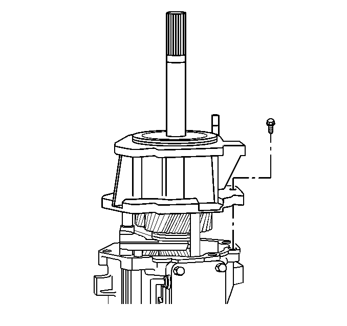
Notice: Use the correct fastener in the correct location. Replacement fasteners
must be the correct part number for that application. Fasteners requiring
replacement or fasteners requiring the use of thread locking compound or sealant
are identified in the service procedure. Do not use paints, lubricants, or
corrosion inhibitors on fasteners or fastener joint surfaces unless specified.
These coatings affect fastener torque and joint clamping force and may damage
the fastener. Use the correct tightening sequence and specifications when
installing fasteners in order to avoid damage to parts and systems.
- Install the extension housing and the extension housing retainer bolts.
Tighten
Tighten the bolts to 35 N·m (26 Ib ft).

- Remove the plug from the
adapter plate.
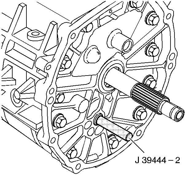
- Install the J 39444-2
through the adapter plate plug hole.
- Screw J 39444-2
into the countershaft extension.
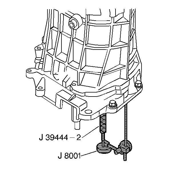
- Measure the countershaft
extension end play using the following procedure:
| 7.1. | Install a J 8001
so the tip is on the end of the countershaft extension end play rod. |
| 7.2. | Rotate the transmission in the vertical position. |
| 7.3. | Move the countershaft extension up and down using the J 39444-2
. |
| 7.4. | Record the measurement. |
- Select a shim to achieve 0.05-0.13 mm (0.002-0.005 in)
axial play.
- Remove the J 8001
.
- Remove the J 39444-2
.
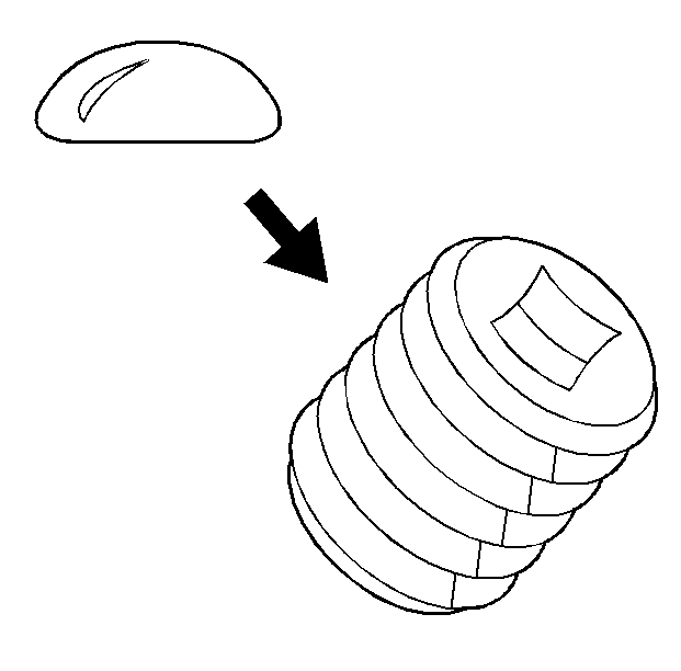
- Apply sealant GM P/N United
States 12346004, GM P/N Canada 10953480 or the
equivalent to the plug threads.

- Install the adapter plate
plug.
Tighten
Tighten the plug to 27 N·m (20 Ib ft).

- Install the countershaft
extension.
- Install the countershaft extension bearing race.

- Install the extension housing bolts and the extension housing.
Shimming Procedures GTO
Input Shaft, Mainshaft, and Countershaft
Tools Required
- Rotate the transmission adapter plate to the vertical position.

- Install the following assemblies in order:
| 2.1. | The input shaft to the adapter plate |
| 2.2. | The 4TH speed gear blocking ring |
| 2.3. | The mainshaft assembly |
| 2.4. | The countershaft (Lift up the mainshaft enough to install the countershaft.) |

- Install the transmission case.
Notice: Use the correct fastener in the correct location. Replacement fasteners
must be the correct part number for that application. Fasteners requiring
replacement or fasteners requiring the use of thread locking compound or sealant
are identified in the service procedure. Do not use paints, lubricants, or
corrosion inhibitors on fasteners or fastener joint surfaces unless specified.
These coatings affect fastener torque and joint clamping force and may damage
the fastener. Use the correct tightening sequence and specifications when
installing fasteners in order to avoid damage to parts and systems.
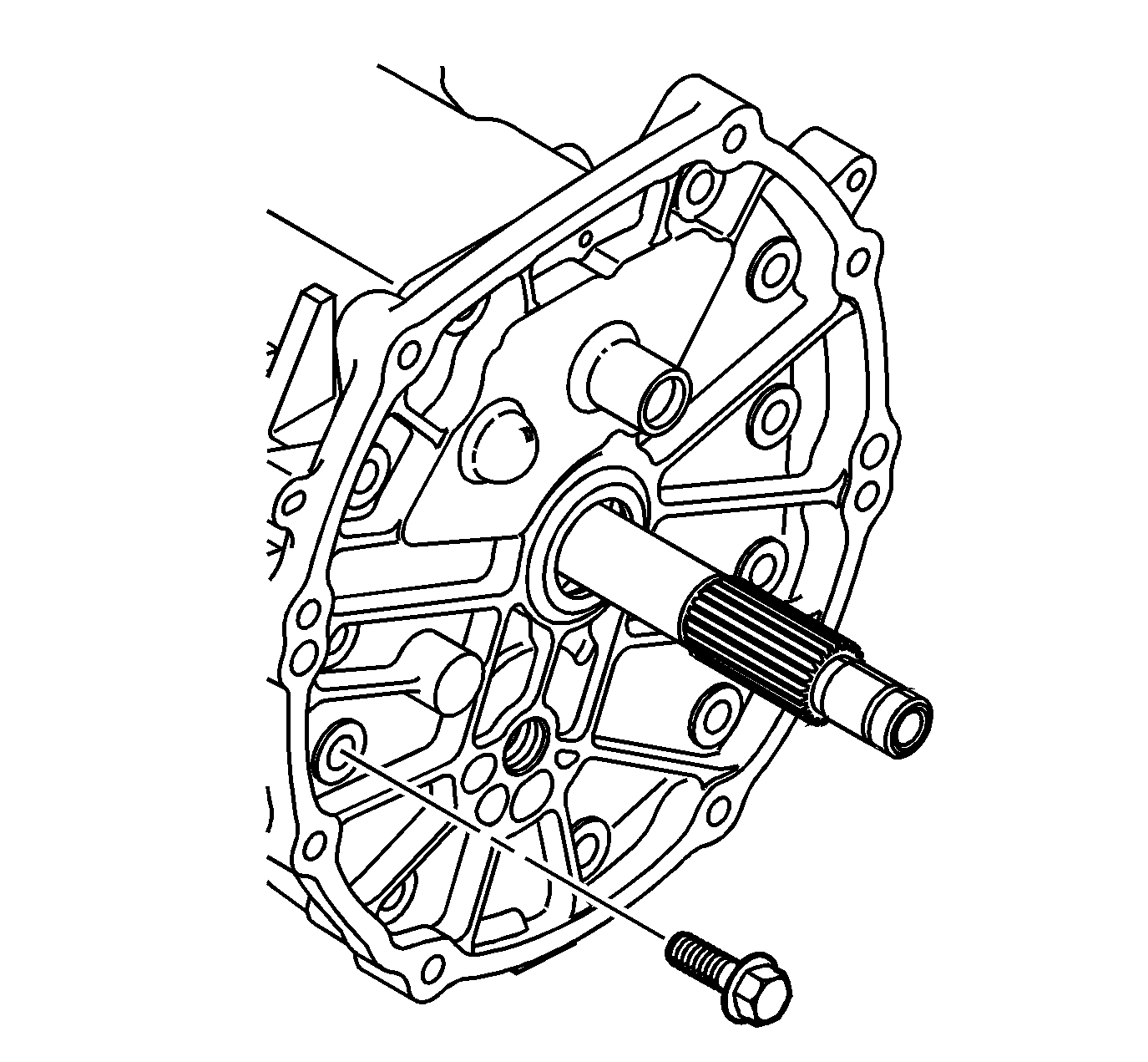
- Install the adapter plate to transmission case bolts.
Tighten
Tighten the bolts to 35 N·m (26 Ib ft).

- Measure the input shaft/mainshaft end play using the
following procedure:
| 5.1. | Place the tip of the J 8001
-3 on
the end of the mainshaft. |
| 5.2. | Move the input shaft up and down. |
| 5.3. | Record the measurement. |
- Select a shim to achieve 0.00-0.05 mm (0.000-0.002 in)
preload.
- Remove the J 8001
-3.

- Remove the adapter plate plug.

- Place the tip of the J 8001
-3
on the end of the countershaft.
- Measure the countershaft end play using the following procedure:
| 10.1. | Install the J 39444-1
through the
adapter plate plug hole. Screw the J 39444-1
into the countershaft. |
| 10.2. | Move the countershaft up and down with the countershaft end play rod J 39444-1
. |
| 10.3. | Record the measurement. |
- Select a shim to achieve 0.00-0.05 mm (0.000-0.002 in)
preload.
- Remove the J 8001
-3.
- Remove the J 39444-1
.

- Remove the adapter plate to the transmission case
bolts.

- Remove the transmission case.

- Remove the following parts in order:
| 16.1. | The countershaft (Lift up the mainshaft enough to remove the countershaft). |
| 16.2. | The mainshaft assembly |
| 16.3. | The 4TH speed gear blocking ring and the input shaft from the adapter
plate |
| 16.4. | The input shaft bearing race |
| 16.5. | The countershaft bearing race |
Countershaft Extension
Tools Required
| • | J 39444-2 Countershaft Extension
End Play Rod |
Important: The following procedure cannot be performed
accurately until the countershaft shimming procedure has been completed and the
transmission has been assembled to the point of installing the countershaft extension.
- Rotate the transmission in the horizontal position.

- Install the countershaft extension to the countershaft.
Make sure the splines fully engage.
Notice: Use the correct fastener in the correct location. Replacement fasteners
must be the correct part number for that application. Fasteners requiring
replacement or fasteners requiring the use of thread locking compound or sealant
are identified in the service procedure. Do not use paints, lubricants, or
corrosion inhibitors on fasteners or fastener joint surfaces unless specified.
These coatings affect fastener torque and joint clamping force and may damage
the fastener. Use the correct tightening sequence and specifications when
installing fasteners in order to avoid damage to parts and systems.
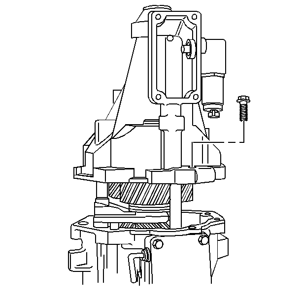
- Install the extension housing and the extension housing retainer bolts.
Tighten
Tighten the bolts to 35 N·m (26 Ib ft).

- Remove the plug from the adapter plate.

- Install the J 39444-2
through
the adapter plate plug hole.
- Screw J 39444-2
into the countershaft
extension.

- Measure the countershaft extension end play using
the following procedure:
| 7.1. | Install a J 8001
so the tip is
on the end of the countershaft extension end play rod. |
| 7.2. | Rotate the transmission in the vertical position. |
| 7.3. | Move the countershaft extension up and down using the J 39444-2
. |
| 7.4. | Record the measurement. |
- Select a shim to achieve 0.05-0.13 mm (0.002-0.005 in)
axial play.
- Remove the J 8001
.
- Remove the J 39444-2
.

- Apply sealant GM P/N 12346004 (Canadian P/N 10953480)
or the equivalent to the plug threads.

- Install the adapter plate plug.
Tighten
Tighten the plug to 27 N·m (20 Ib ft).

- Install the countershaft extension.
- Install the countershaft extension bearing race.

- Install the extension housing bolts and the extension
housing.
Shimming Procedures CTSV
Input Shaft, Mainshaft, and Countershaft
Tools Required
- Rotate the transmission adapter plate to the vertical position.

- Install the following assemblies in order:
| 2.1. | The input shaft to the adapter plate |
| 2.2. | The 4TH speed gear blocking ring |
| 2.3. | The mainshaft assembly |
| 2.4. | The countershaft (Lift up the mainshaft enough to install the countershaft.) |

- Install the transmission case.
Notice: Use the correct fastener in the correct location. Replacement fasteners
must be the correct part number for that application. Fasteners requiring
replacement or fasteners requiring the use of thread locking compound or sealant
are identified in the service procedure. Do not use paints, lubricants, or
corrosion inhibitors on fasteners or fastener joint surfaces unless specified.
These coatings affect fastener torque and joint clamping force and may damage
the fastener. Use the correct tightening sequence and specifications when
installing fasteners in order to avoid damage to parts and systems.
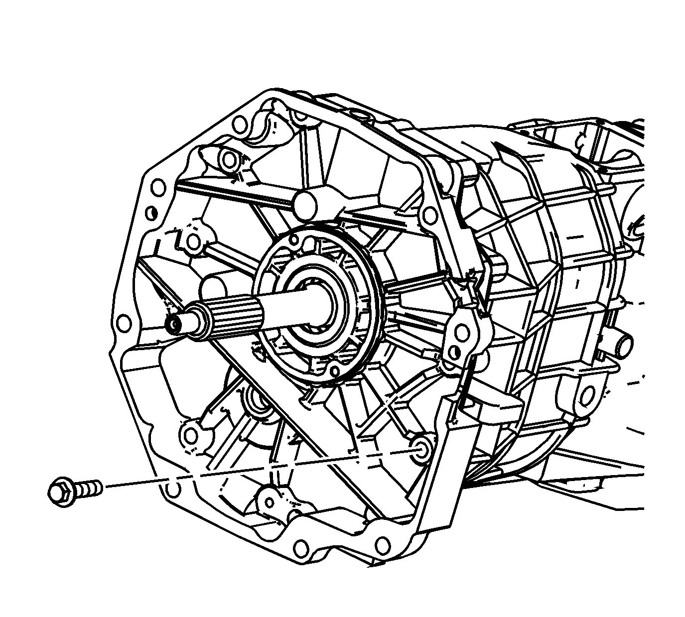
- Install the adapter plate to transmission case bolts.
Tighten
Tighten the bolts to 35 N·m (26 Ib ft).

- Measure the input shaft/mainshaft end play using the
following procedure:
| 5.1. | Place the tip of the J 8001
-3 on
the end of the mainshaft. |
| 5.2. | Move the input shaft up and down. |
| 5.3. | Record the measurement. |
- Select a shim to achieve 0.00-0.05 mm (0.000-0.002 in)
preload.
- Remove the J 8001
-3.
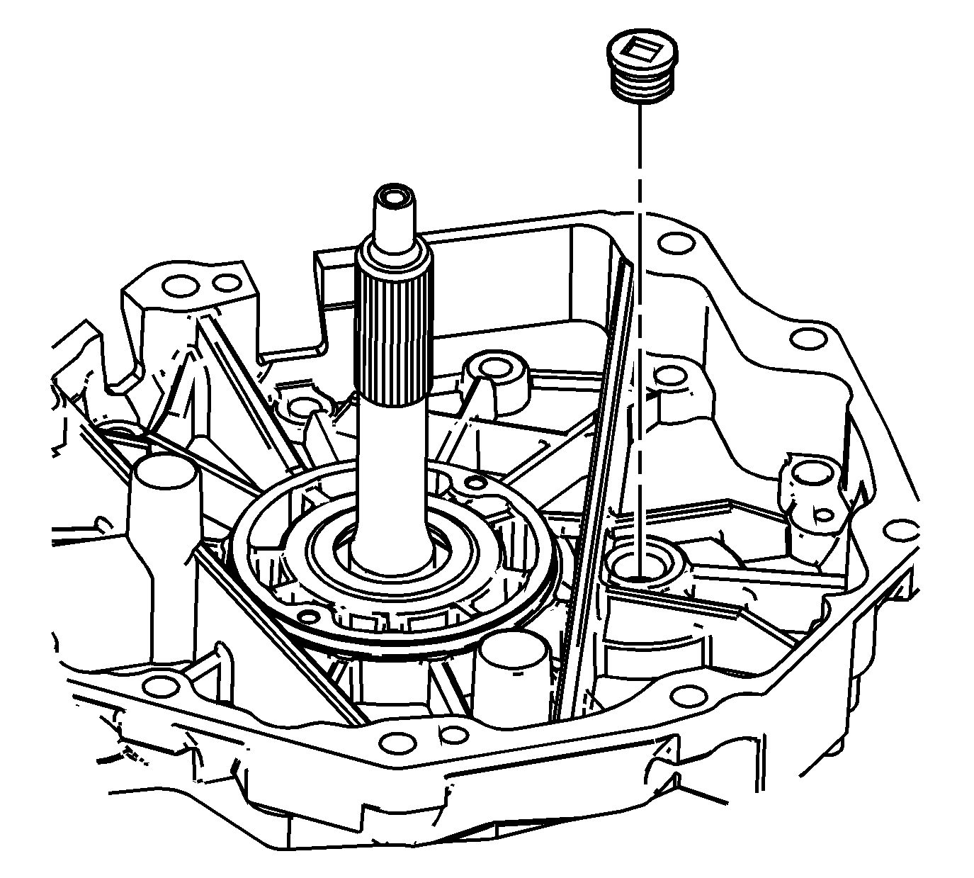
- Remove the adapter plate plug.

- Place the tip of the J 8001
-3
on the end of the countershaft.
- Measure the countershaft end play using the following procedure:
| 10.1. | Install the J 39444-1
through the
adapter plate plug hole. Screw the J 39444-1
into the countershaft. |
| 10.2. | Move the countershaft up and down with the countershaft end play rod J 39444-1
. |
| 10.3. | Record the measurement. |
- Select a shim to achieve 0.00-0.05 mm (0.000-0.002 in)
preload.
- Remove the J 8001
-3.
- Remove the J 39444-1
.

- Remove the adapter plate to the transmission case
bolts.

- Remove the transmission case.

- Remove the following parts in order:
| 16.1. | The countershaft (Lift up the mainshaft enough to remove the countershaft). |
| 16.2. | The mainshaft assembly |
| 16.3. | The 4TH speed gear blocking ring and the input shaft from the adapter
plate |
| 16.4. | The input shaft bearing race |
| 16.5. | The countershaft bearing race |
Countershaft Extension
Tools Required
| • | J 39444-2 Countershaft Extension
End Play Rod |
Important: The following procedure cannot be performed
accurately until the countershaft shimming procedure has been completed and the
transmission has been assembled to the point of installing the countershaft extension.
- Rotate the transmission in the horizontal position.

- Install the countershaft extension to the countershaft.
Make sure the splines fully engage.

Notice: Use the correct fastener in the correct location. Replacement fasteners
must be the correct part number for that application. Fasteners requiring
replacement or fasteners requiring the use of thread locking compound or sealant
are identified in the service procedure. Do not use paints, lubricants, or
corrosion inhibitors on fasteners or fastener joint surfaces unless specified.
These coatings affect fastener torque and joint clamping force and may damage
the fastener. Use the correct tightening sequence and specifications when
installing fasteners in order to avoid damage to parts and systems.
- Install the extension housing and the extension housing retainer bolts.
Tighten
Tighten the bolts to 35 N·m (26 Ib ft).

- Remove the plug from the adapter plate.
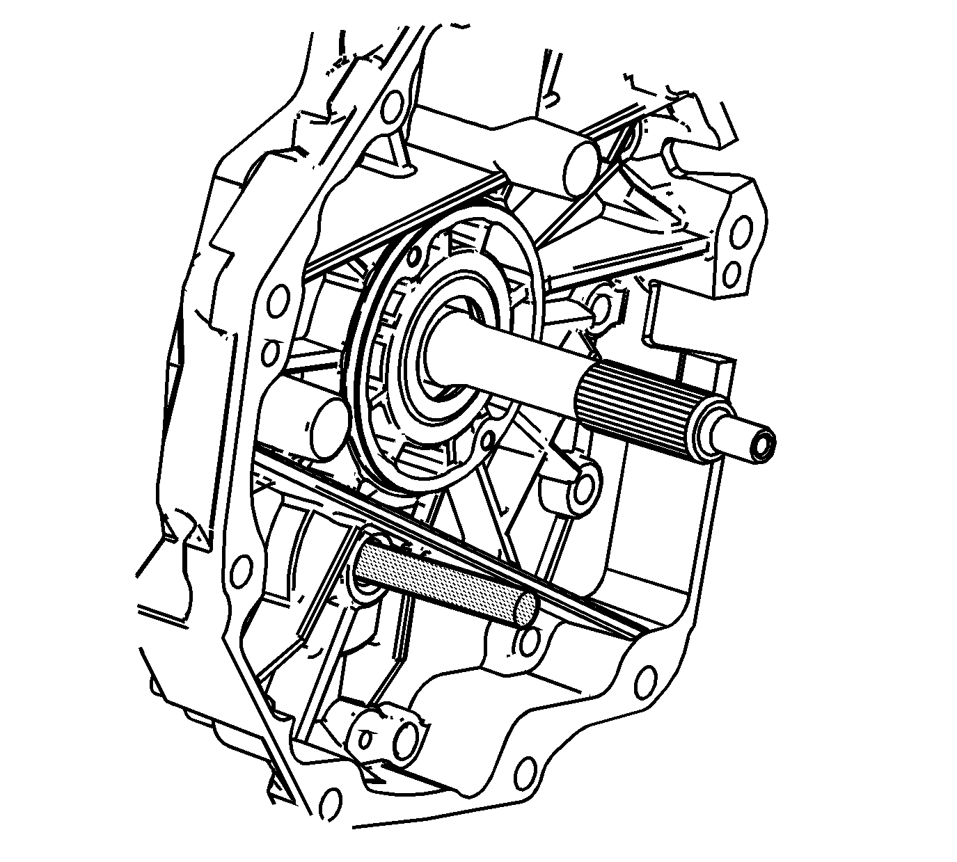
- Install the J 39444-2
through
the adapter plate plug hole.
- Screw J 39444-2
into the countershaft
extension.

- Measure the countershaft extension end play using
the following procedure:
| 7.1. | Install a J 8001
so the tip is
on the end of the countershaft extension end play rod. |
| 7.2. | Rotate the transmission in the vertical position. |
| 7.3. | Move the countershaft extension up and down using the J 39444-2
. |
| 7.4. | Record the measurement. |
- Select a shim to achieve 0.05-0.13 mm (0.002-0.005 in)
axial play.
- Remove the J 8001
.
- Remove the J 39444-2
.

- Apply sealant GM P/N 12346004 (Canadian P/N 10953480)
or the equivalent to the plug threads.

- Install the adapter plate plug.
Tighten
Tighten the plug to 27 N·m (20 Ib ft).

- Install the countershaft extension.
- Install the countershaft extension bearing race.

- Install the extension housing bolts and the extension
housing.


