Tool Required
| • | J 42155
Getrag Axle Differential Housing Lifting Tool |
| • | J 42173
Getrag Axle Ring Gear Holder |
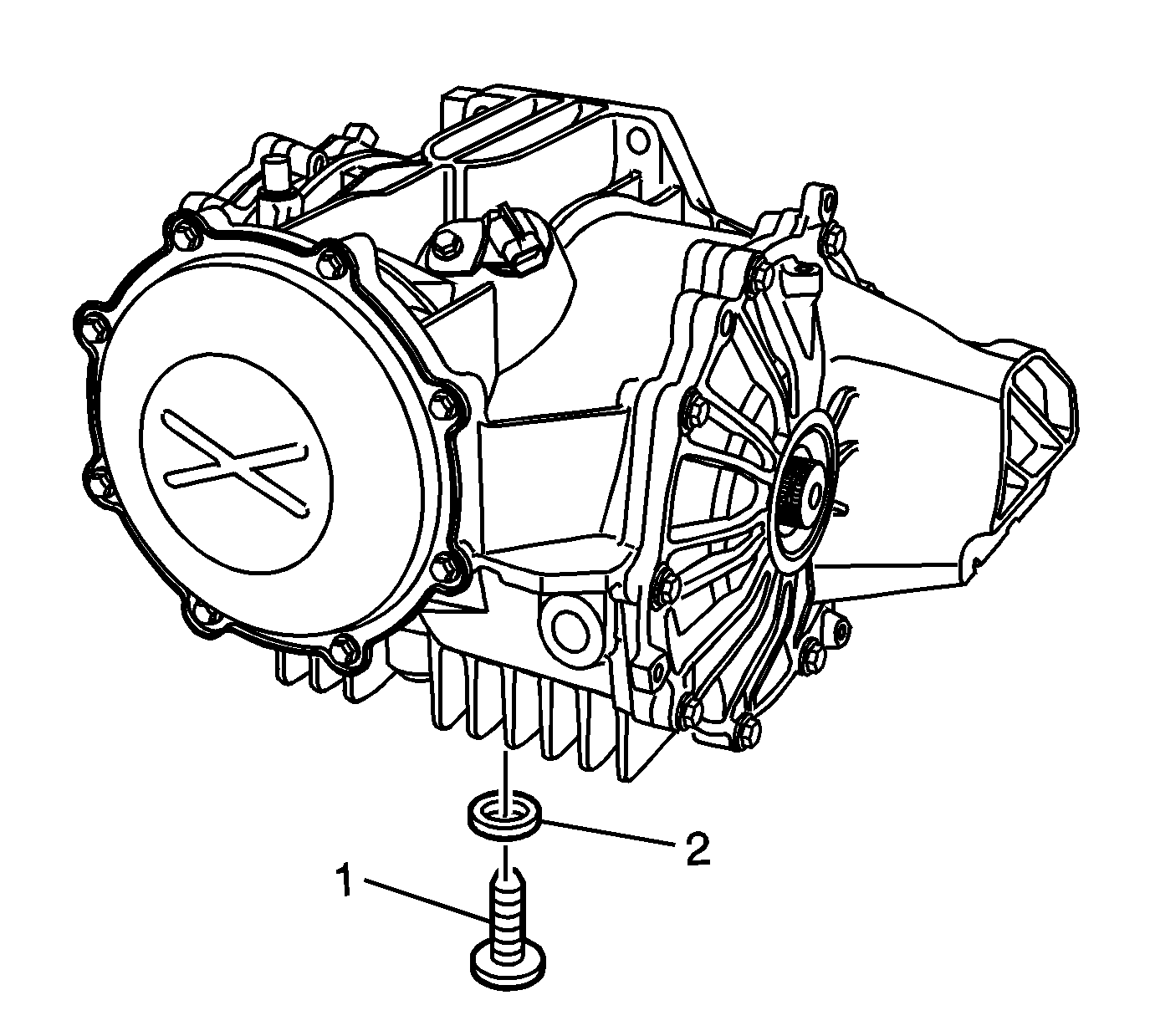
- Remove the drain plug (1) and washer (2) and allow the fluid to drain.
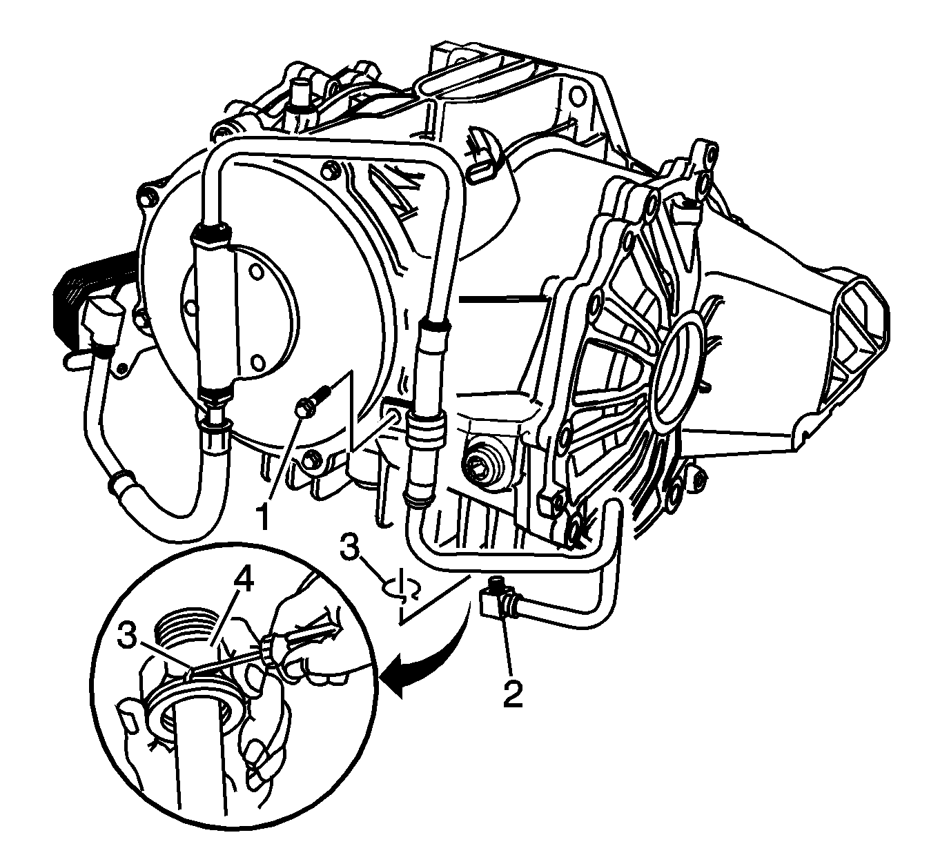
- To drain the fluid from models equipped
with a pump and cooler, perform the following steps:
| 2.1. | Remove the bolt (1) retaining the lower inlet pipe clamp. |
| 2.2. | Using a bent tip screwdriver, remove the quick connect fitting retaining ring (3) from the quick connect fitting (4), and discard the retaining ring. |
| 2.3. | Drain the fluid by pulling the lower inlet pipe (2) straight out of the quick connect fitting. |
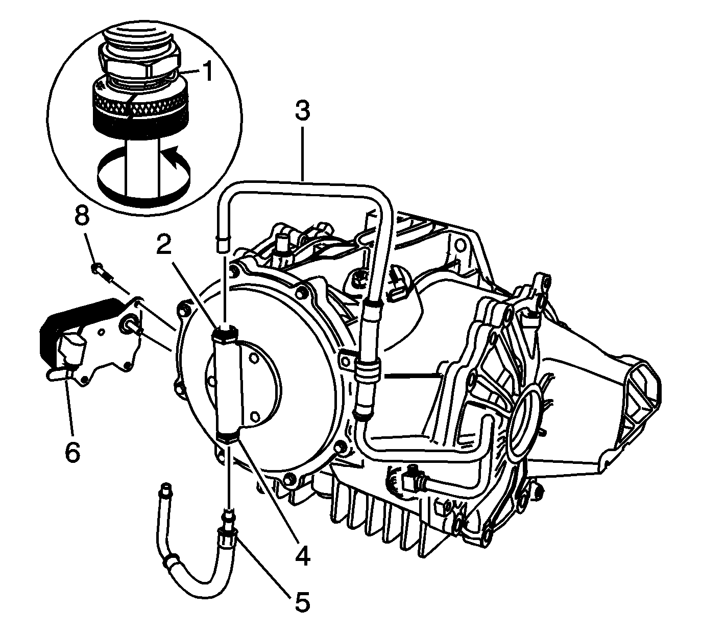
- For models equipped with a pump and cooler, perform the following steps to remove
the cooler and pipes:
| 3.1. | Using the
J 41623-B
, remove the inlet and outlet pipes by aligning notches on the
J 41623-B
with quick connect fittings (2, 4, 6)
and rotating the tool to release pipes (3 and 5) from the quick connect fittings. |
| 3.2. | Remove the 3 cooler retaining bolts (8). |
| 3.3. | Remove the cooler (7). |
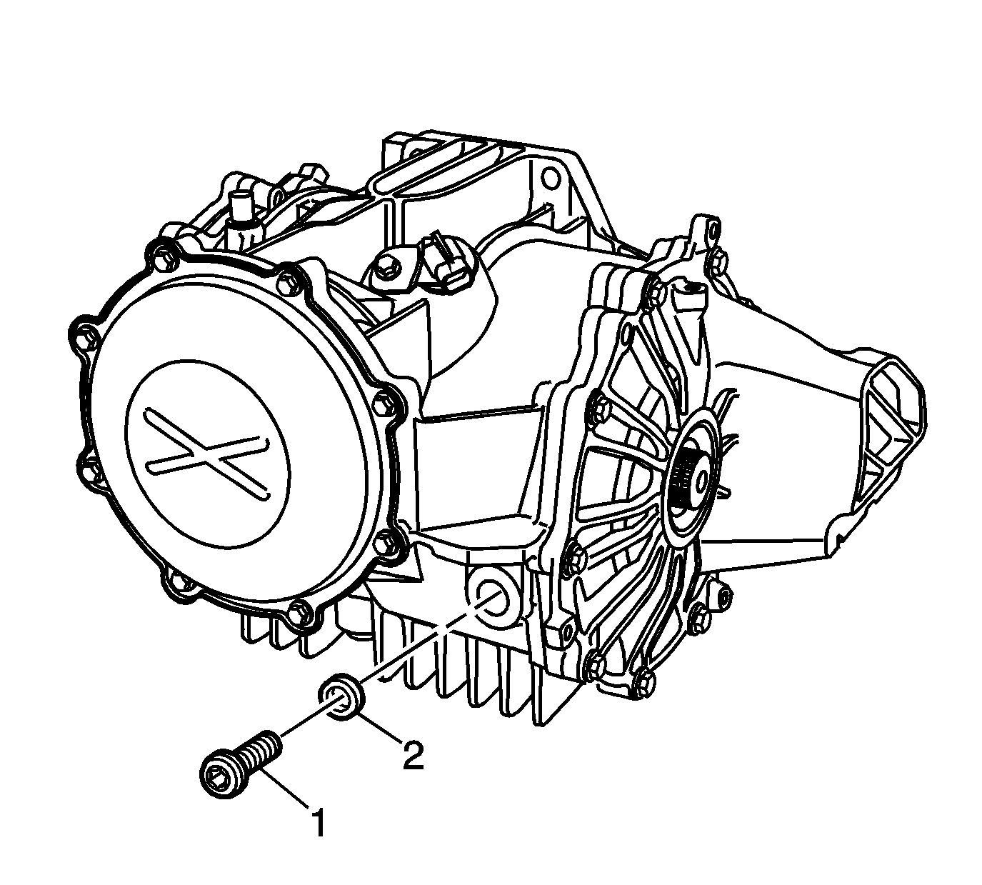
- Remove the fill plug (1) and washer (2).
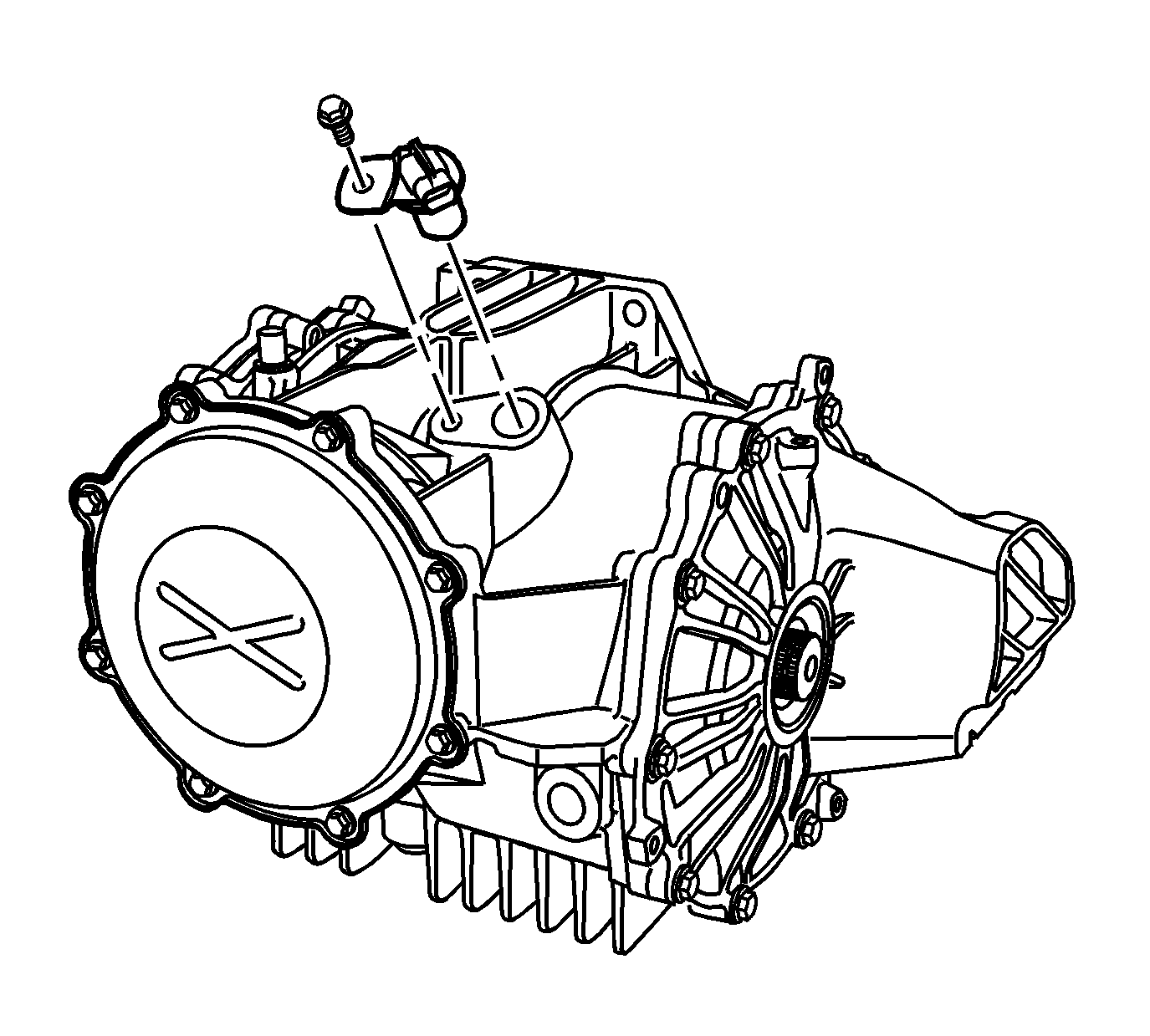
- Remove the vehicle speed sensor and bolt.
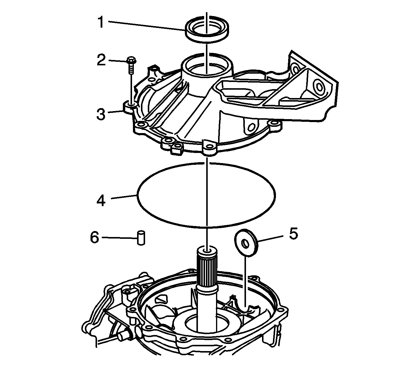
- Remove the left cover (3) and bolts (2).
- Remove the O-ring (4) and oil seal (1) from the cover.
- Remove the magnet (5) and dowel (6) from the carrier.
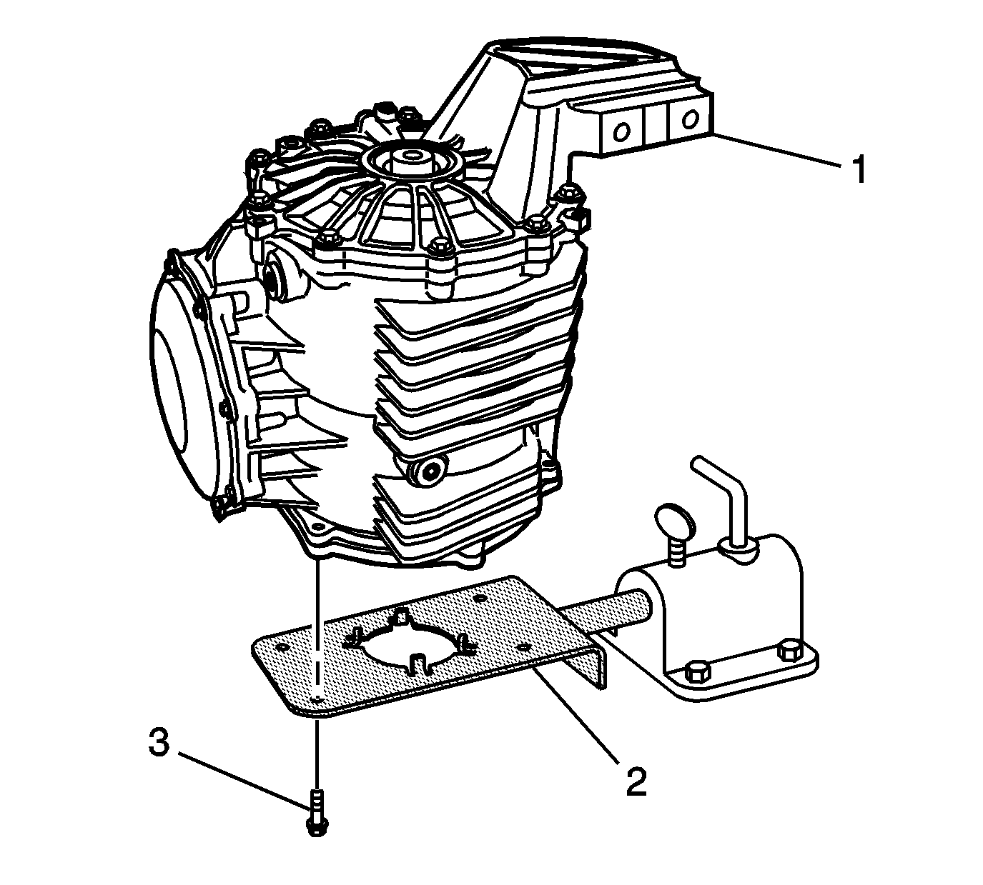
- Install the differential assembly (1) onto the
J 42173
(2).
Notice: Use the correct fastener in the correct location. Replacement fasteners
must be the correct part number for that application. Fasteners requiring
replacement or fasteners requiring the use of thread locking compound or sealant
are identified in the service procedure. Do not use paints, lubricants, or
corrosion inhibitors on fasteners or fastener joint surfaces unless specified.
These coatings affect fastener torque and joint clamping force and may damage
the fastener. Use the correct tightening sequence and specifications when
installing fasteners in order to avoid damage to parts and systems.
- Install 4 M8 x 1.25 bolts (3).
Tighten
Tighten the bolts to 30 N·m (22 lb ft).
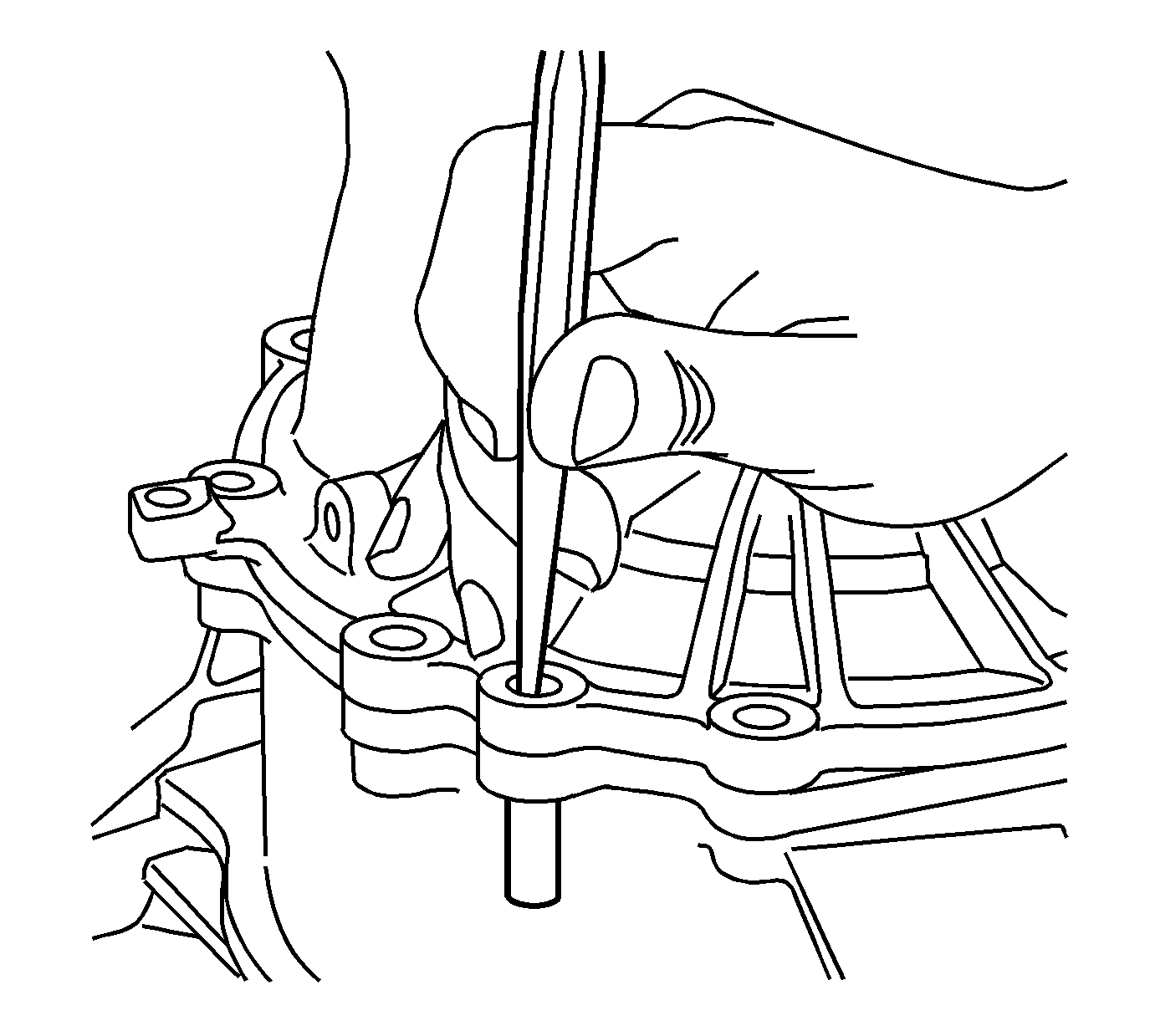
- Using a punch, remove the cover alignment pin.
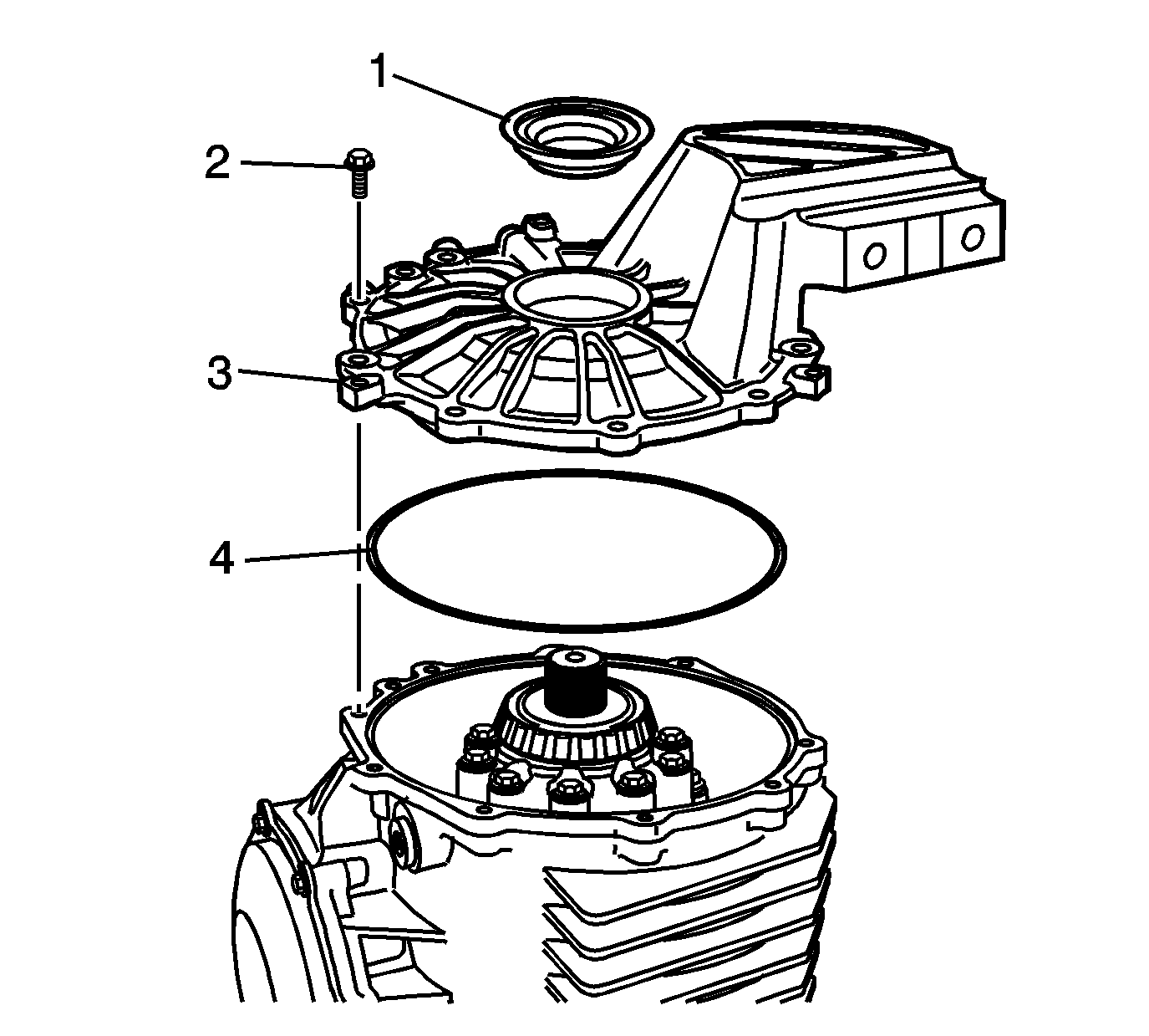
- Remove the right cover (3) and bolts (2) from the differential.
- Remove the O-ring (4) and oil seal (1) from the cover.
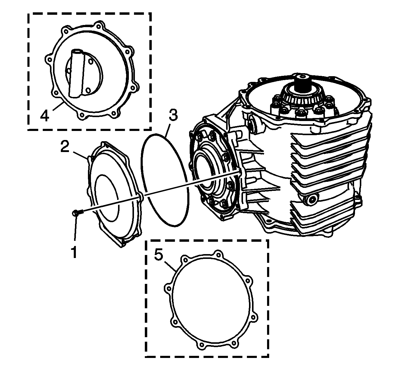
Important: Note the location of the rear cover bolt/stud for assembly.
- Remove the rear cover (2), bolts (3), O-ring (1), pump - some models (4), or gasket - some models (5).
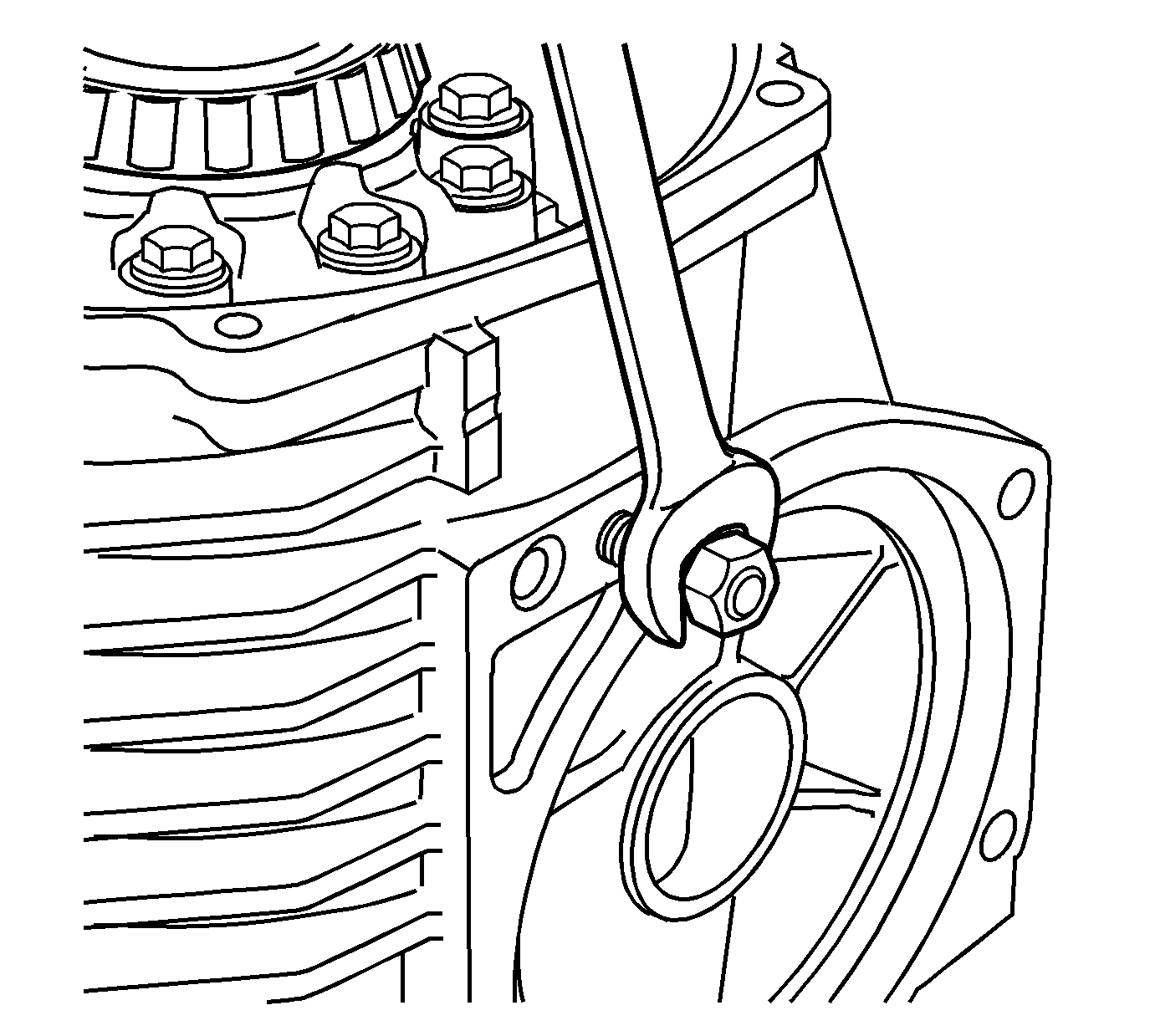
- Install 2 M10 x 1.5 nuts onto the transmission stud. Remove the stud from the
differential.
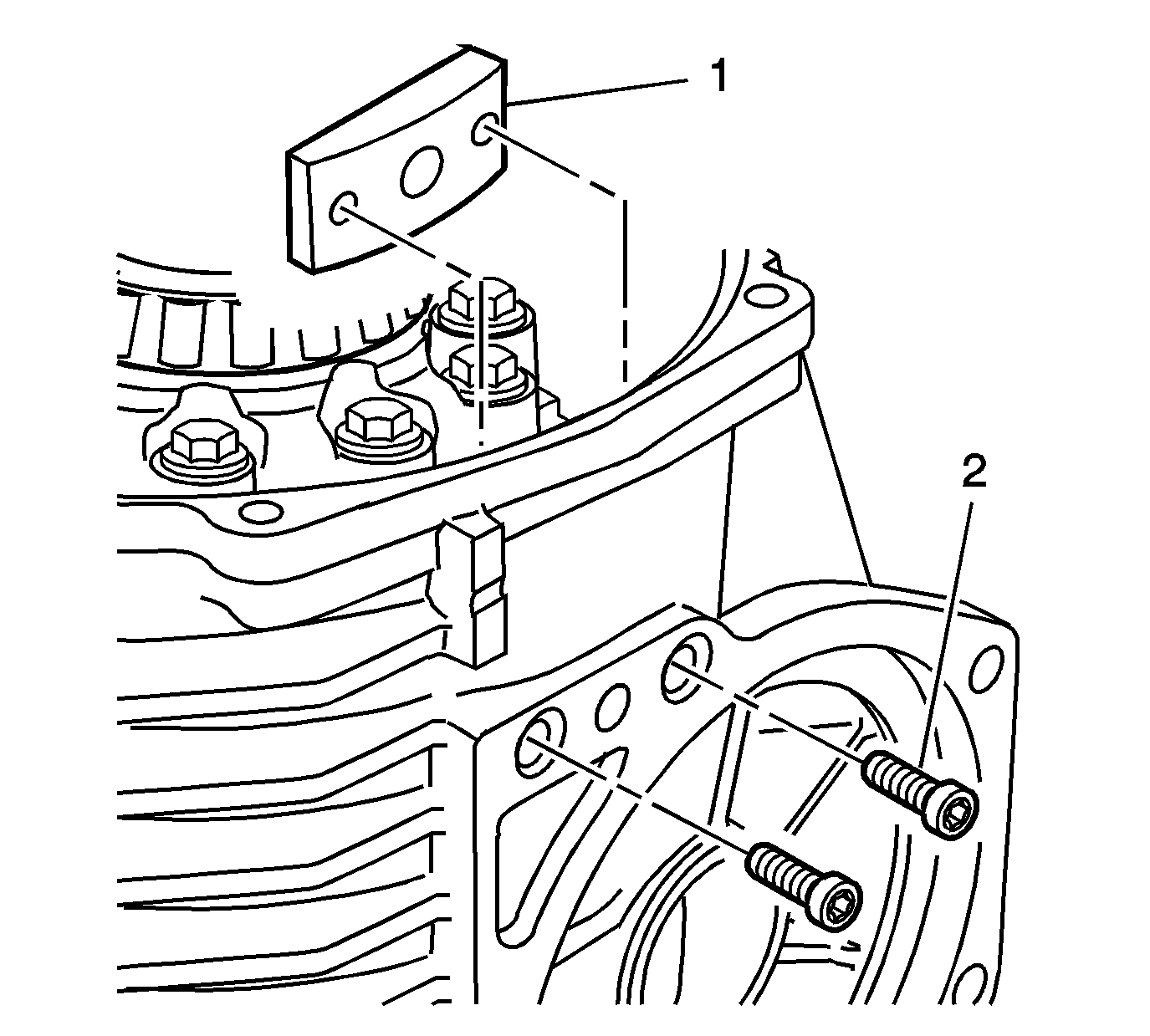
- Remove the bolts (2) and mount (1) from the differential. Note and mark the position and direction of the mount.
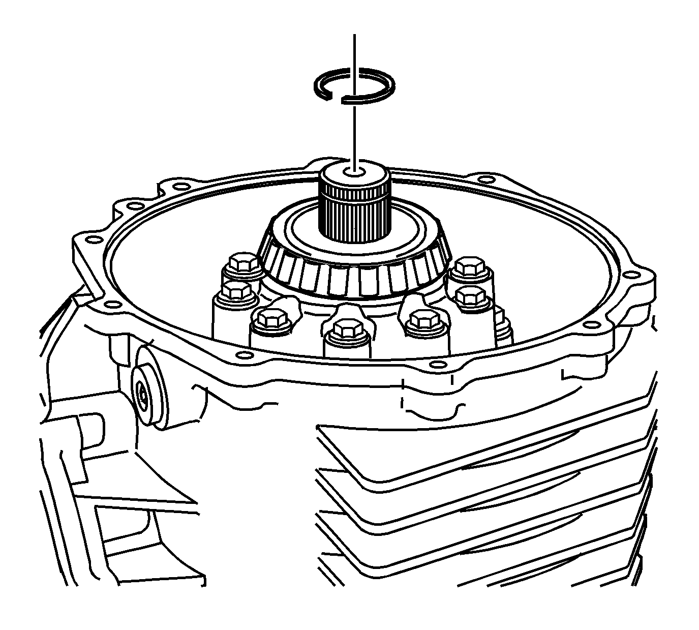
- Remove the C-clip from the output shaft.
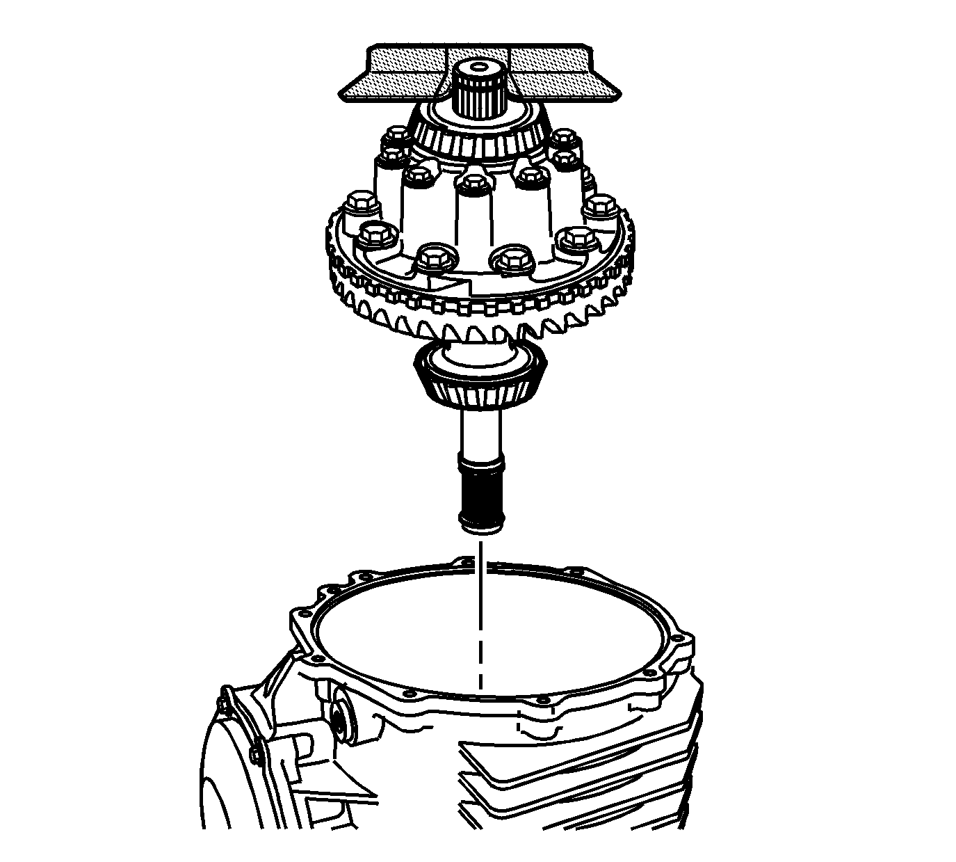
- Install the
J 42155
into the groove of the output shaft
in order to remove the differential case assembly.
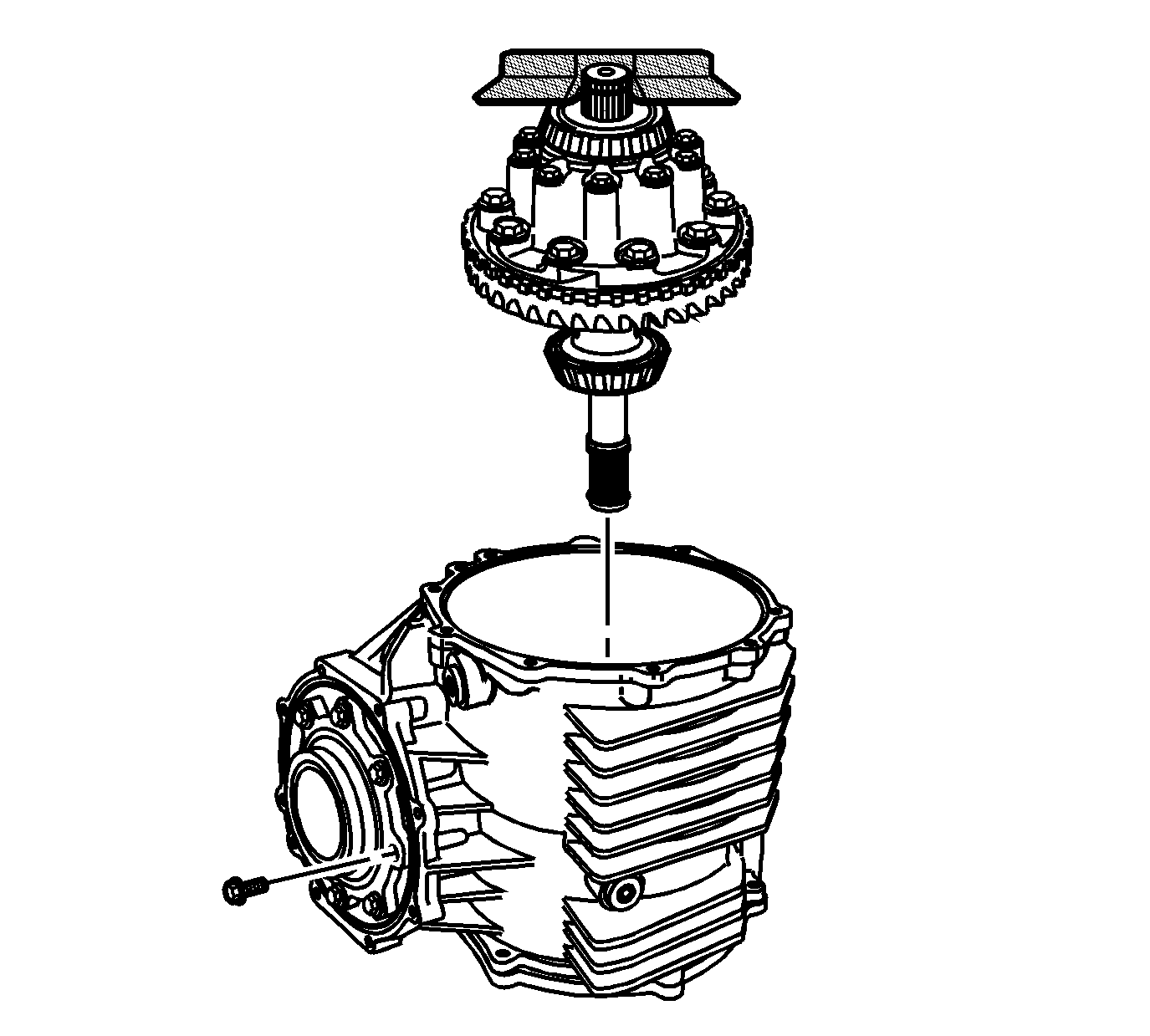
- Remove the pinion housing/cage bolts.
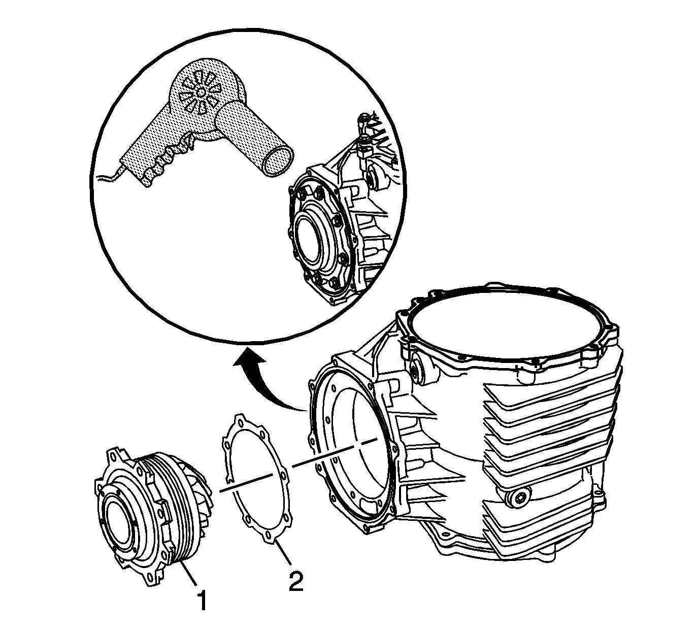
- Using the
J 25070
, heat the differential housing around
the pinion housing. Heating the housing will ease in pinion removal.
- Remove the pinion housing/cage assembly (1) and shims (2) from the differential housing. Mark or tag the shims for assembly.
Locate 2 screwdrivers or pry bars to the flange area of the pinion housing/cage to ease
in removal.
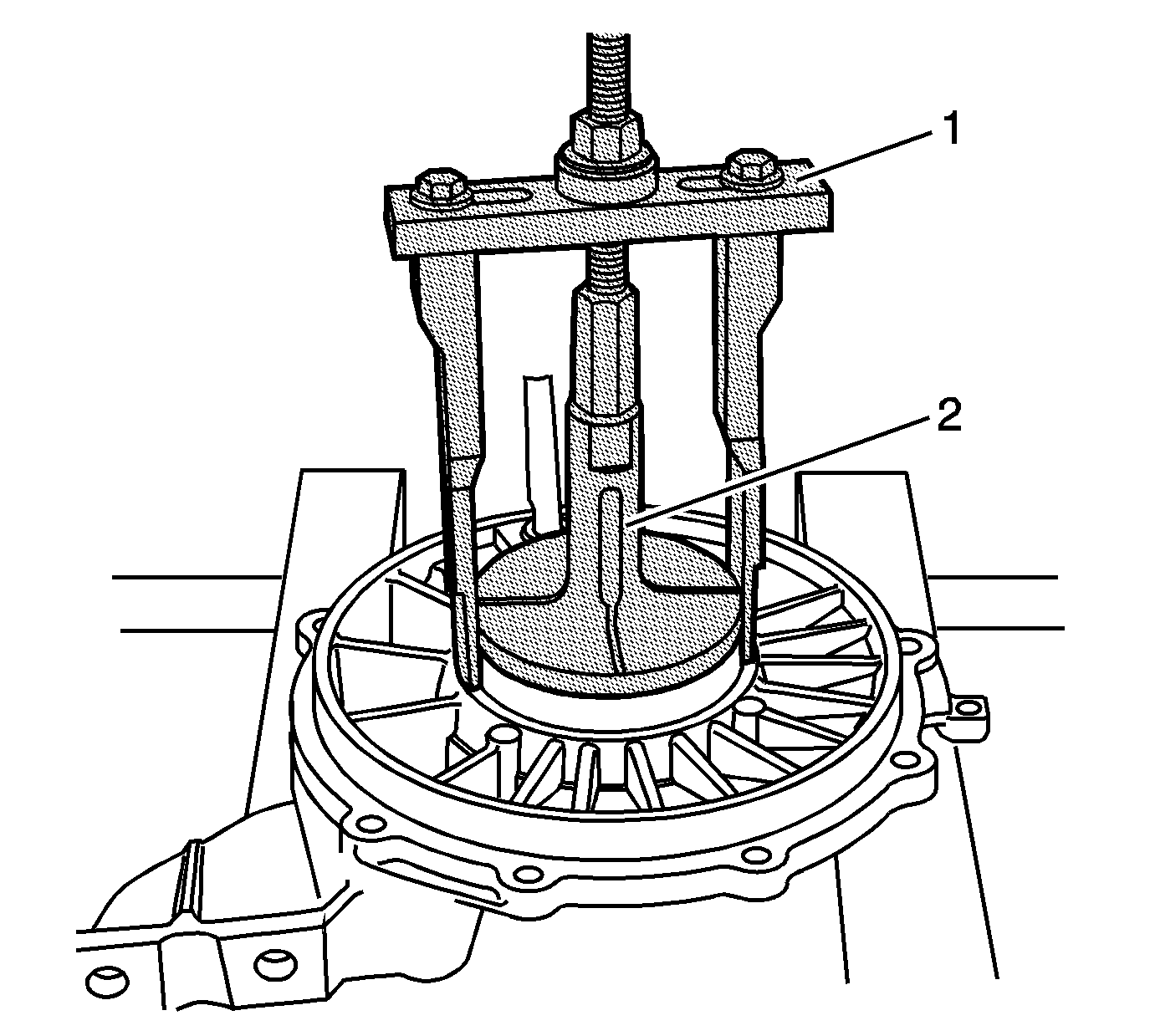
- Install the
DT-47596
(2) into the right cover.
Tighten securely into the bearing cup.
- Place
J 45124
(1) over
DT-47596
(2). Adjust legs for best fit. Install supplied bolt, nut, thrust bearing and washer. Hold
the bolt and tighten the nut to remove the bearing cup and shim.
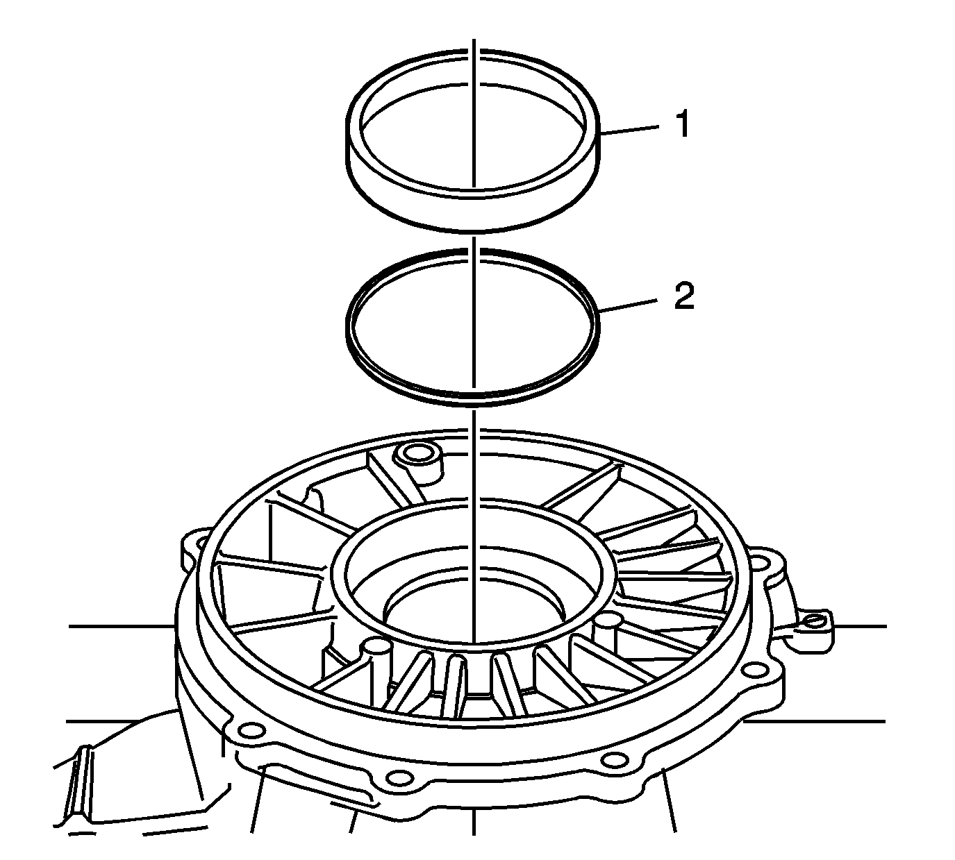
- Remove the bearing cup (1) and shim (2). Mark or tag the shims for
assembly.
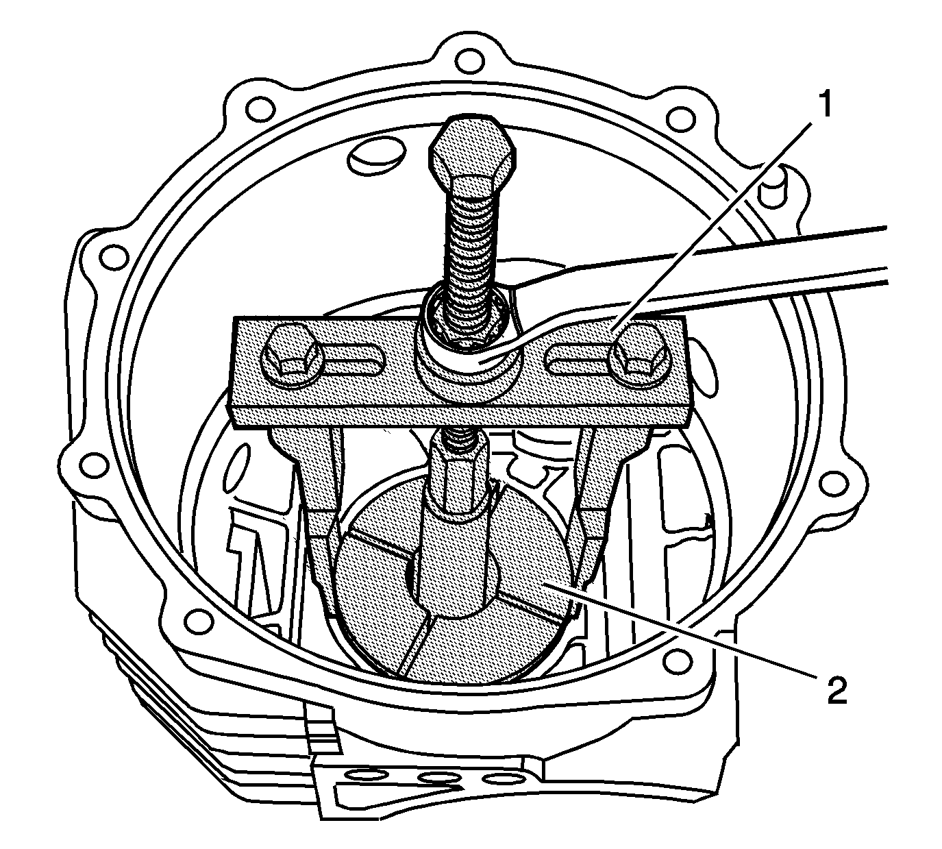
- Install the
DT-47596
(2)
into the differential housing, behind the left bearing cup. Tighten securely into the bearing cup.
- Place
J 45124
(1) over
DT-47596
(2). Adjust legs for best fit. Install supplied bolt, nut, thrust bearing and washer. Hold
the bolt and tighten the nut to remove the bearing cup and shim.
- Remove the cup (2) and shim (1) from the differential housing. Mark or tag the shims for assembly.


