For 1990-2009 cars only
Removal Procedure
- Remove the shift control knob. Refer to Transmission Control Lever Knob Replacement .
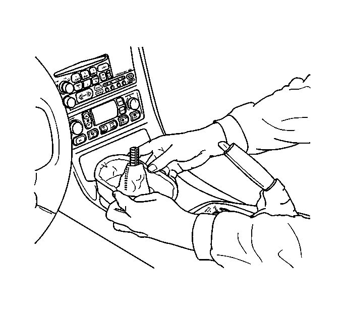
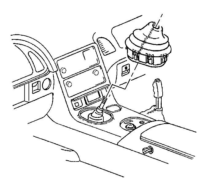
- Grasp the sides of the shift control boot and apply light pressure in toward the shift control lever to begin to release the shift boot retaining tabs from the instrument panel (I/P) accessory trim plate.
- Using light pressure, continue to release the remaining boot retaining tabs.
- Lift the boot away from the trim plate and remove the boot.
- Remove the I/P accessory trim plate. Refer to Instrument Panel Accessory Trim Plate Replacement in Instrument Panel, Gages and Console.
- Remove the acoustic boot for the shiftier.
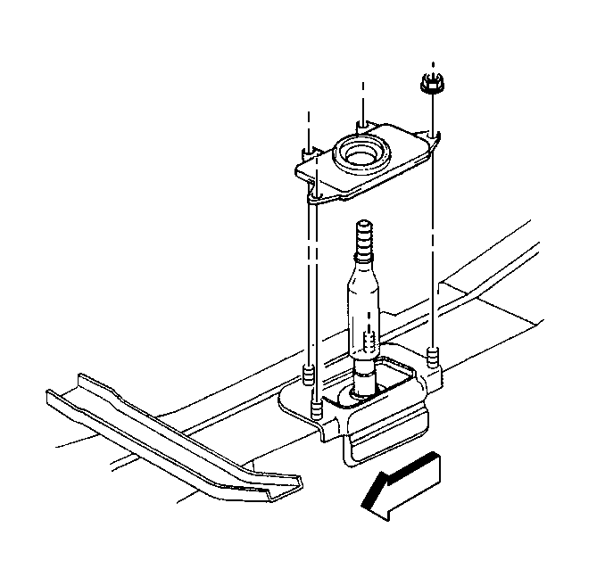
- Remove the shift control closeout boot retaining nuts.
- Remove the shift control closeout boot.
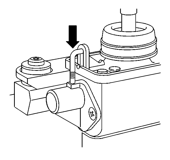
- Place the shiftier into NEUTRAL.
- Press down to engage the shift control neutral lock pin.
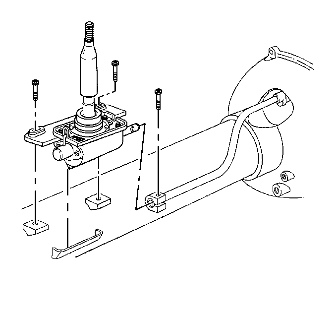
- Remove the transmission shift rod clamp bolt.
- Remove the shift control mounting bolts.
- Raise the shift control to release the locator from the shiftier bracket on the side of the driveline support assembly.
- Release the shift control from the transmission shift rod clamp and remove the shift control assembly.
Installation Procedure
- Install the shift control assembly to the transmission shift rod clamp.
- Lower the shiftier into position and insert the locator into the shiftier bracket on the side of the driveline support assembly.
- Install the shift control mounting bolts.
- Install the transmission shift rod clamp bolt.
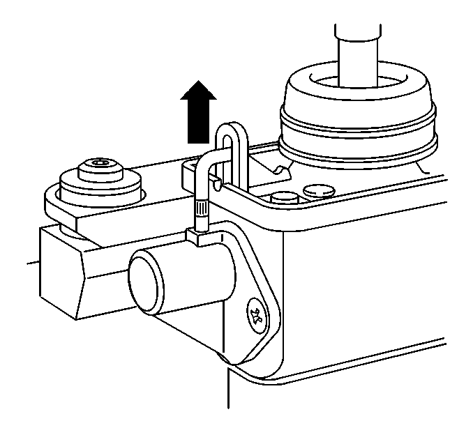
- Lift to release the shift control neutral lock pin.
- Install the shift control closeout boot.
- Install the shift control closeout boot retaining nuts.
- Install the acoustic boot.
- Install the I/P accessory trim plate. Refer to Instrument Panel Accessory Trim Plate Replacement in Instrument Panel, Gages and Console.
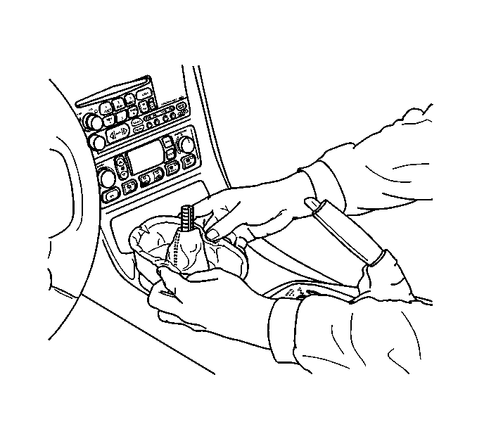
- Install the shift control boot over the shift control lever.
- Align the shift control boot to the I/P accessory trim plate opening, then press to lock the boot retaining tabs.
- Adjust the shape of the boot for appearance, if necessary.
- Install the shift control knob. Refer to Transmission Control Lever Knob Replacement .
- Install the console. Refer to Console Replacement in Instrument Panel, Gages and Console.

Notice: Refer to Fastener Notice in the Preface section.
Tighten
Tighten the shift control mounting bolts to 30 N·m (22 lb ft).
Tighten
Tighten the transmission shift rod clamp bolt to 30 N·m (22 lb ft).
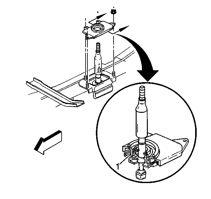
Check that the closeout boot fully seats to the shift control lever seal and the base of the shift control assembly (1).
Tighten
Tighten the shift control closeout boot retaining nuts to 12 N·m (106 lb in).

