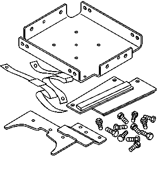
Special Tools
J 42055 Transmission Support Fixture
Removal Procedure
Caution: Refer to Battery Disconnect Caution in the Preface section.
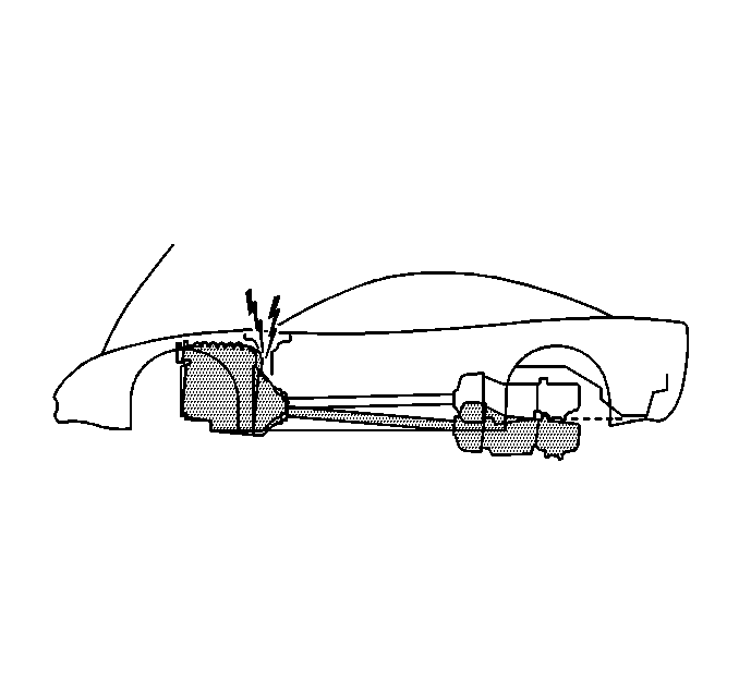
Notice: When tilting down the rear of the driveline, observe the clearance between the rear of the engine and the composite dash panel. Do not allow the engine to rest unsupported against the composite dash panel, or vehicle damage may result.
Notice: When lowering and removing the rear of the driveline, observe the clearance between the rear of the transaxle assembly and the underbody to prevent damage.
- Disconnect the negative battery cable.
- Remove the console. Refer to Console Replacement.
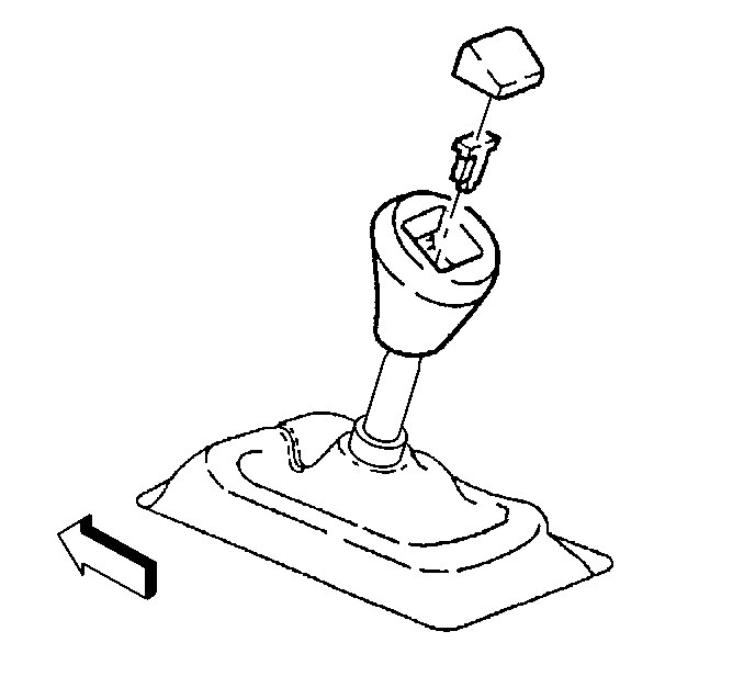
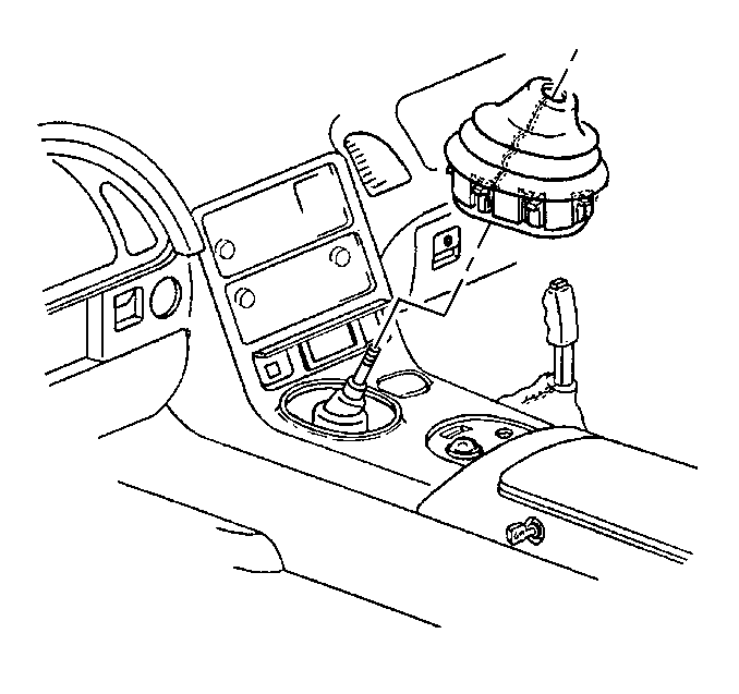
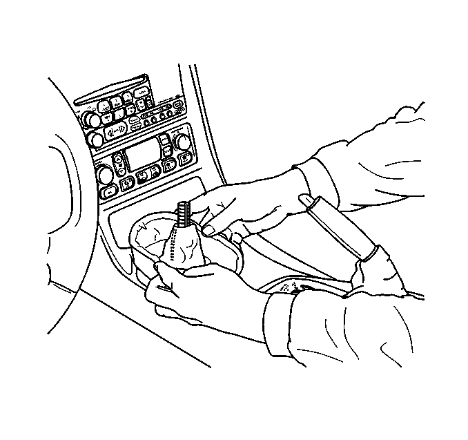
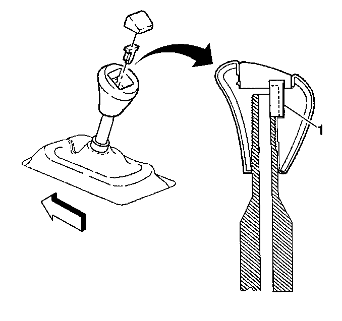
- Carefully pry off the shift control knob button.
- Pry the shift control knob retainer out of the slots and remove the retainer.
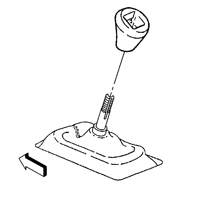
- Unscrew the shift control knob.
- Grasp the sides of the shift control boot and apply light pressure in toward the shift control lever to begin to release the shift boot retaining tabs from the instrument panel (I/P) accessory trim plate.
- Using light pressure, continue to release the remaining boot retaining tabs.
- Lift the boot away from the trim plate and remove the boot.
- Remove the I/P accessory trim plate. Refer to Instrument Panel Accessory Trim Plate Replacement.
- Remove the shift control closeout boot retaining nuts.
- Remove the shift control closeout boot.
- Remove the shift control assembly. Refer to Shift Control Assembly Replacement.
- Remove the left I/P lower insulator panel. Refer to Instrument Panel Insulator Panel Replacement.
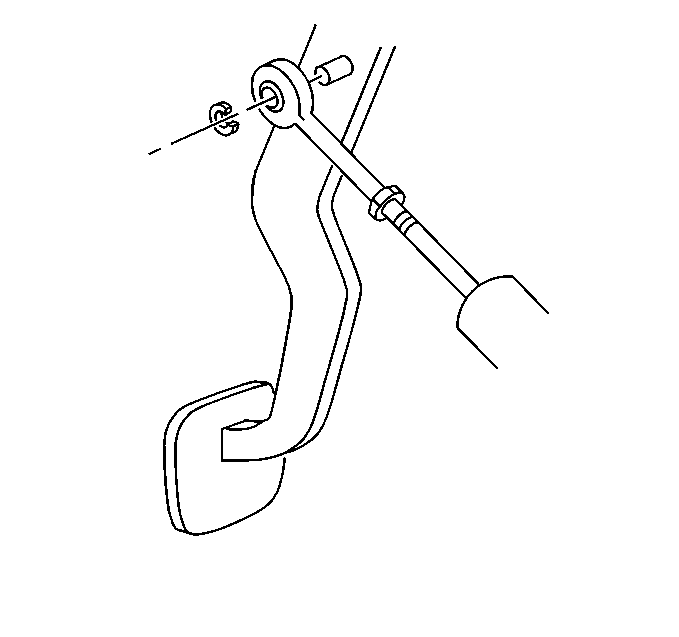
- Remove the clutch master cylinder pushrod retainer.
- Disconnect the clutch master cylinder pushrod from the clutch pedal.
- Raise and support the vehicle. Refer to Lifting and Jacking the Vehicle.
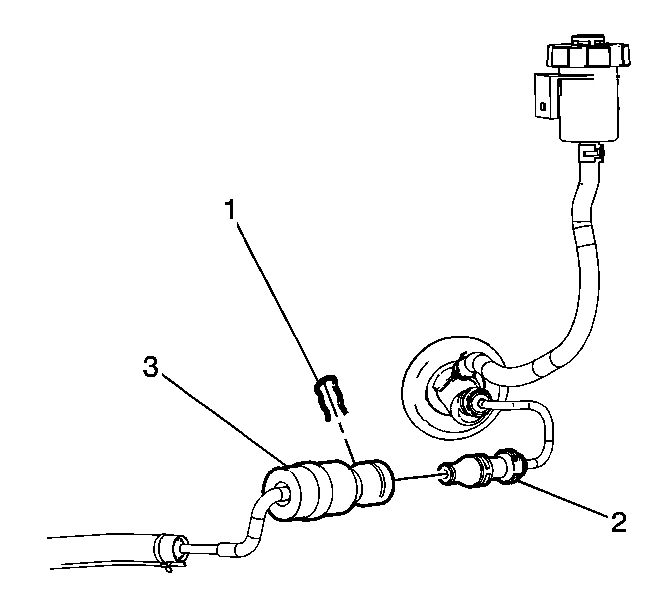
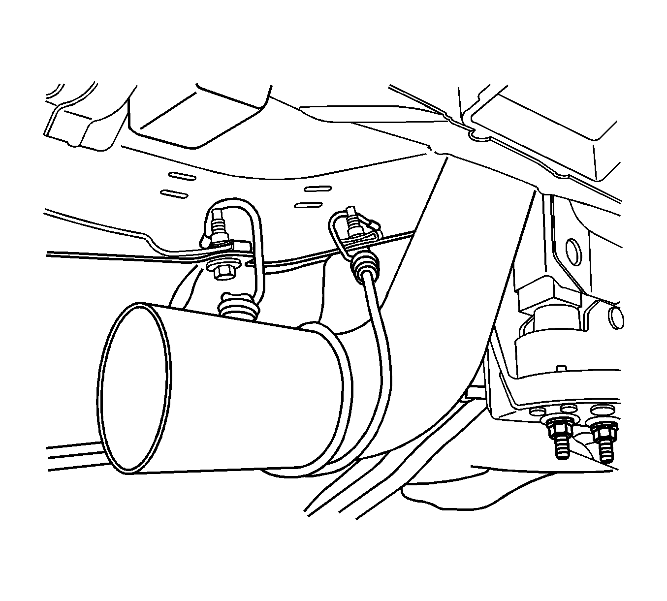
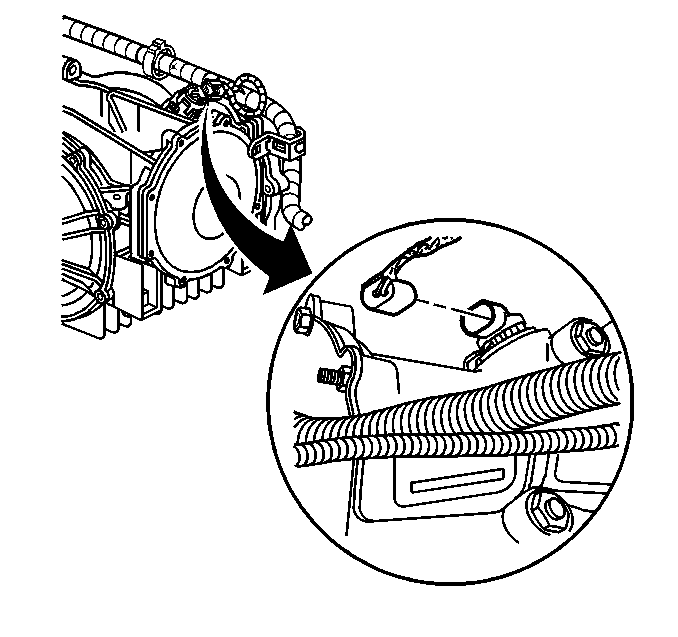
- Remove the clutch actuator cylinder hose (3) from the hose retaining clip, below the power brake booster.
- Remove the hose retaining clip (1) then separate the hoses (2, 3)
- Protect both hose coupling ends from dirt and damage.
- Remove the rear tire and wheel assemblies. Refer to Tire and Wheel Removal and Installation.
- Remove the catalytic converters. Refer to Catalytic Converter Replacement - Left Side and Catalytic Converter Replacement - Right Side.
- Tie off the muffler assemblies to the underbody to support out of the way.
- Remove the floor panel tunnel reinforcement. Refer to Floor Panel Tunnel Panel Reinforcement Replacement.
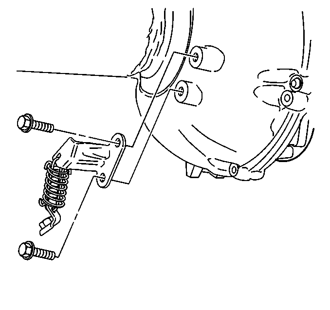
- Remove the rear transverse spring. Refer to Rear Transverse Spring Replacement.
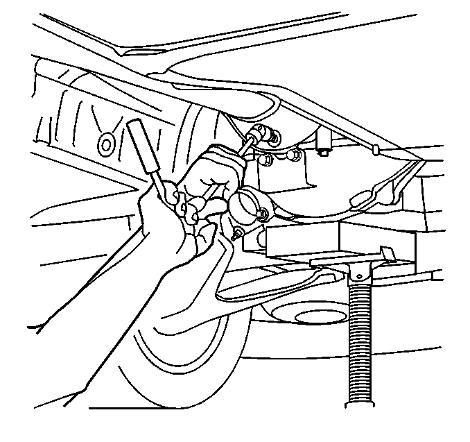
- Support the lower control arm with a straight jack.
- Disconnect the outer tie rod end from the suspension knuckle. Refer to Tie Rod Replacement.
- Remove the shock absorber lower mounting bolt and nut. Refer to Shock Absorber Replacement.
- Disconnect the lower ball joint from the suspension knuckle. Refer to Knuckle Replacement.
- Remove the straight jack from the control arm.
- Repeat steps 25 through 29 for the other side of the vehicle.
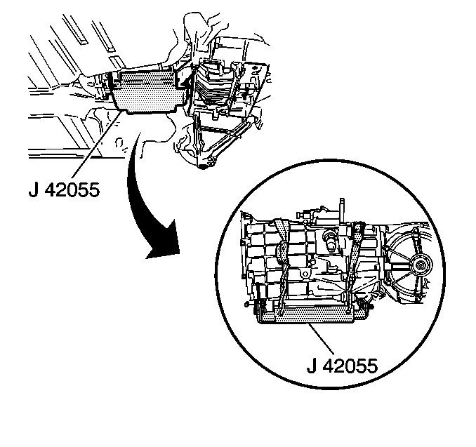
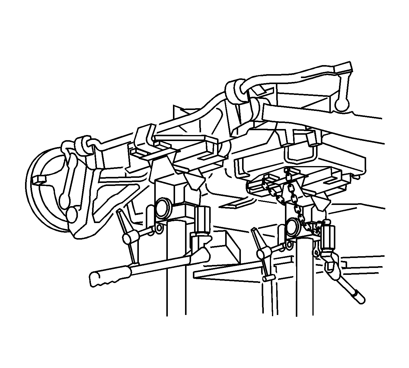
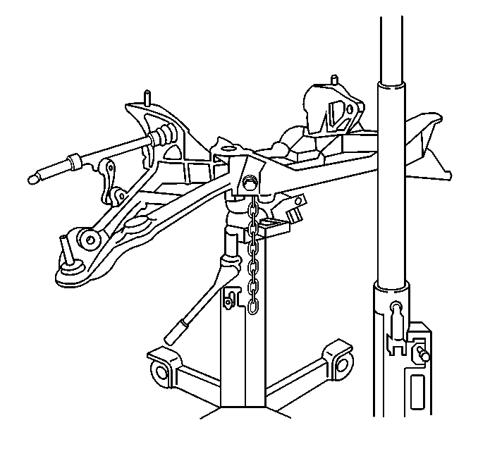
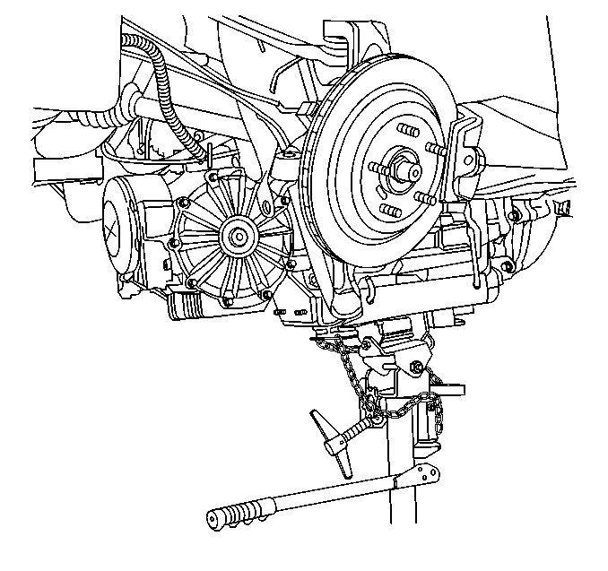
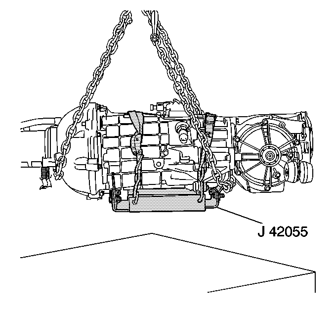
- Assemble the J 42055 .
- Install the J 42055 to a transmission jack.
- Position and firmly secure the J 42055 with the transmission jack to the transmission.
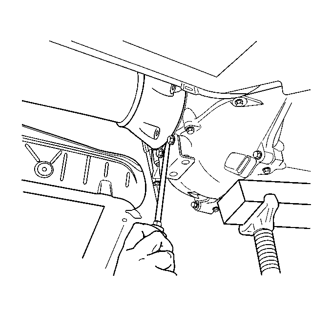
- Disconnect the wiring harness and brake pipe clip retainers from the rear suspension crossmember.
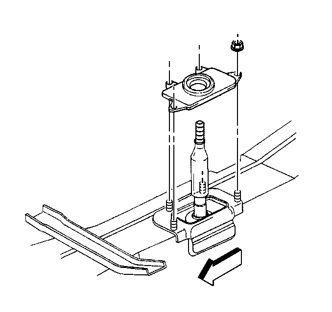
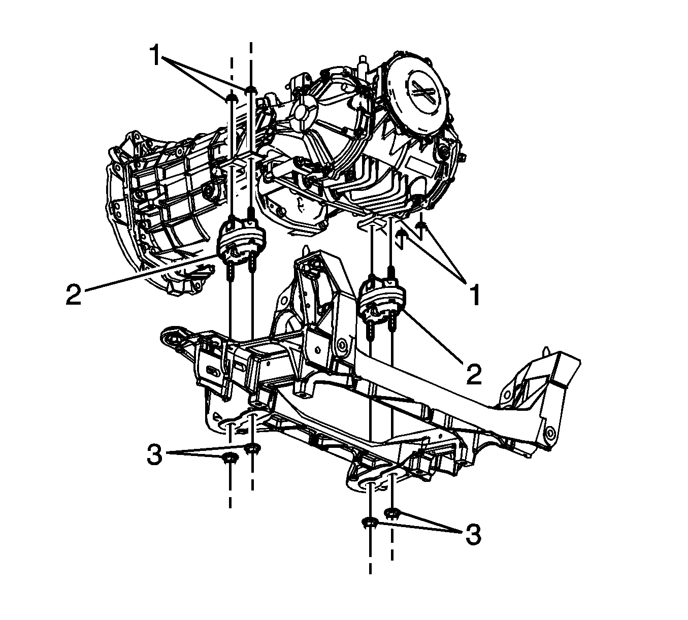
- Remove the transaxle mount (2) to rear crossmember nuts (3).
- Position a transmission jack under the rear suspension crossmember and firmly secure the crossmember to the jack.
- Using ONLY HAND TOOLS, remove the rear suspension crossmember retaining nuts.
- With the aid of an assistant, slowly lower the rear suspension crossmember away from the vehicle frame rails and remove the crossmember.
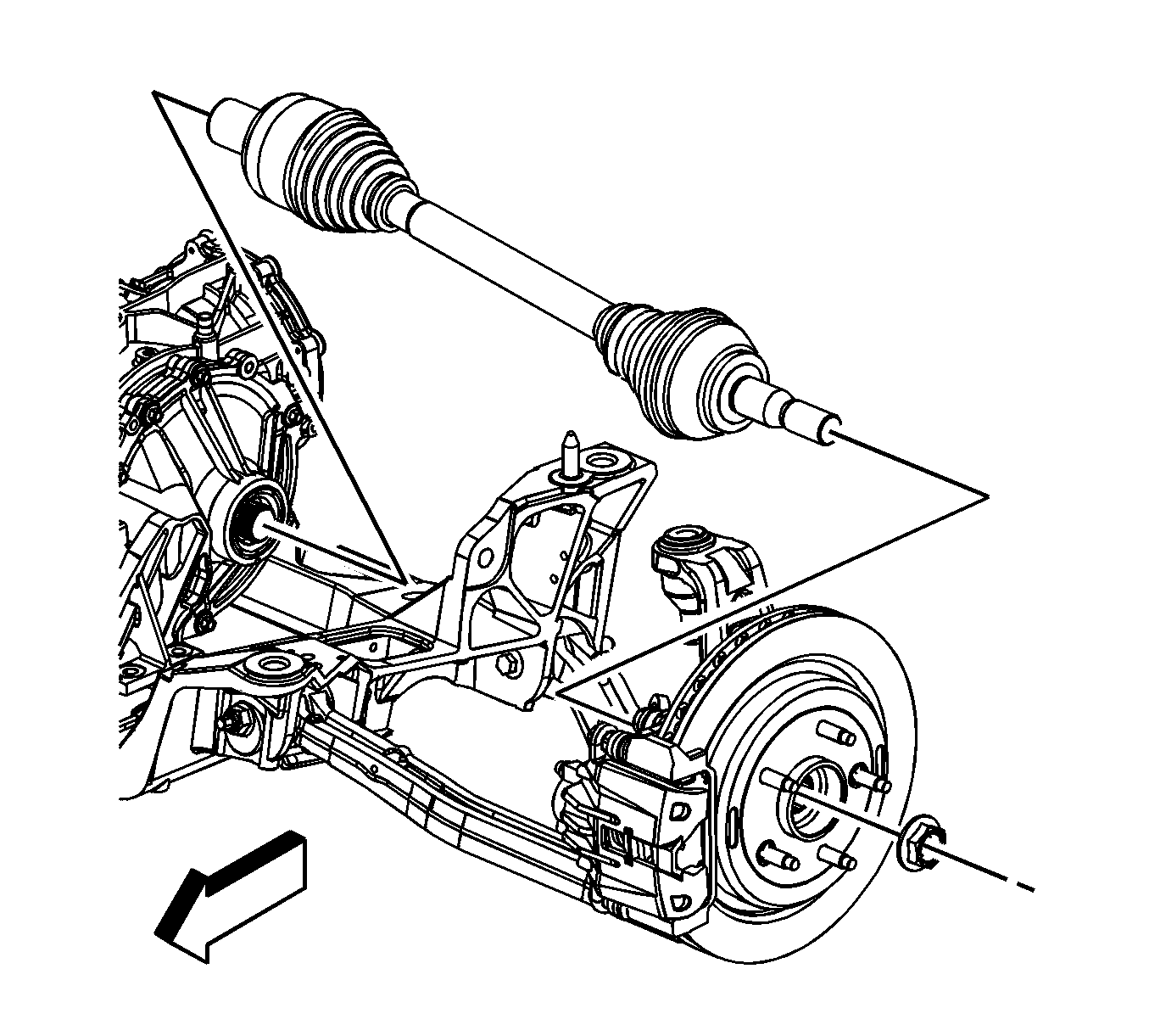
- Remove the transaxle mount (2) to differential nuts (1).
- Using a pry bar, CAREFULLY release the wheel drive shafts from the differential.
- Tie off the wheel drive shafts to the underbody to support out of the way.
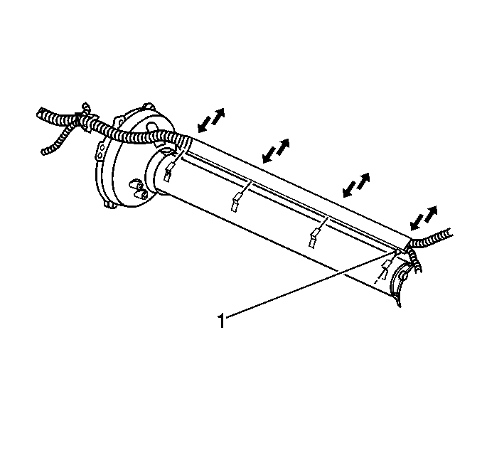
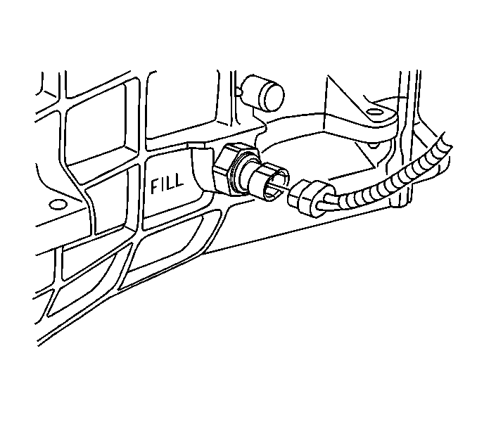
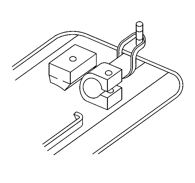
- Release the retainer (1) securing (and positioning) the wiring harness to the L-shaped brackets along the driveline support assembly, then slide the harness up out of the brackets and position out of the way.
- SLOWLY lower the driveline approximately 51 mm (2 in), while simultaneously adjusting the angle of tilt, in order to access the electrical connectors.
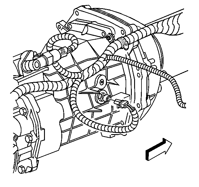
- Disconnect the vehicle speed sensor (VSS) electrical connector.
- Disconnect the wiring harness retainer from the stud at the differential rear cover.
- Disconnect the wiring harness retainer clip from the top of the differential.
- Disconnect the backup lamp switch electrical connector.
- Disconnect the reverse lockout solenoid electrical connector.
- Disconnect the gear select (skip shift) solenoid electrical connector.
- Disconnect the transmission fluid temperature sensor electrical connector, if equipped.
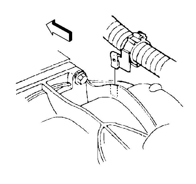
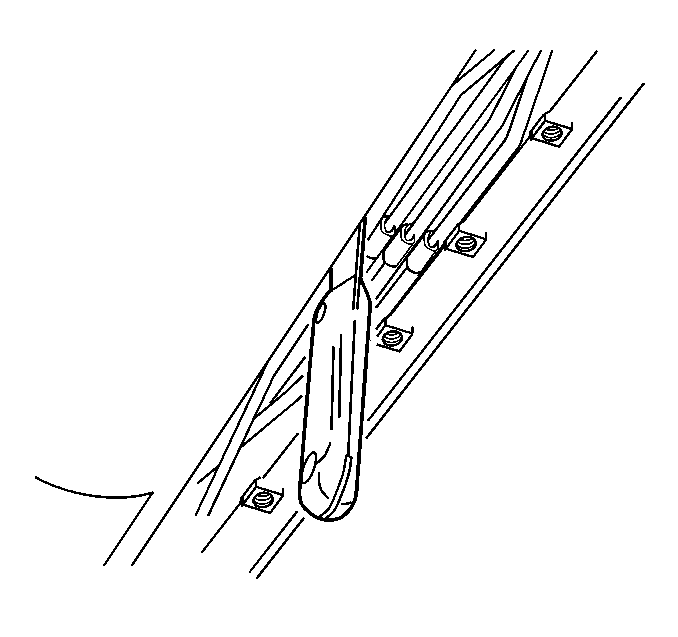
- Insert a putty knife, or similar tool, between the edge of the shifter bracket on the side of the driveline support assembly and the brake pipe retainer on the wall of the driveline tunnel.
- SLOWLY lower the driveline, while simultaneously adjusting the angle of tilt, and observe the relationship between the top rear of the differential and the lowest part of the rear compartment panel floor (the center storage compartment between the frame rails). The differential should not be lowered more than approximately EVEN with the specified body point of reference.
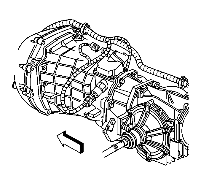
- Release the wiring harness from the harness retainer along the top of the transmission.
- Ensure the wiring harness is free from the driveline being removed.
- Using a block of wood to protect the engine oil pan, place a straight jack under the rear of the engine oil pan to support the engine from stressing the composite dash panel.
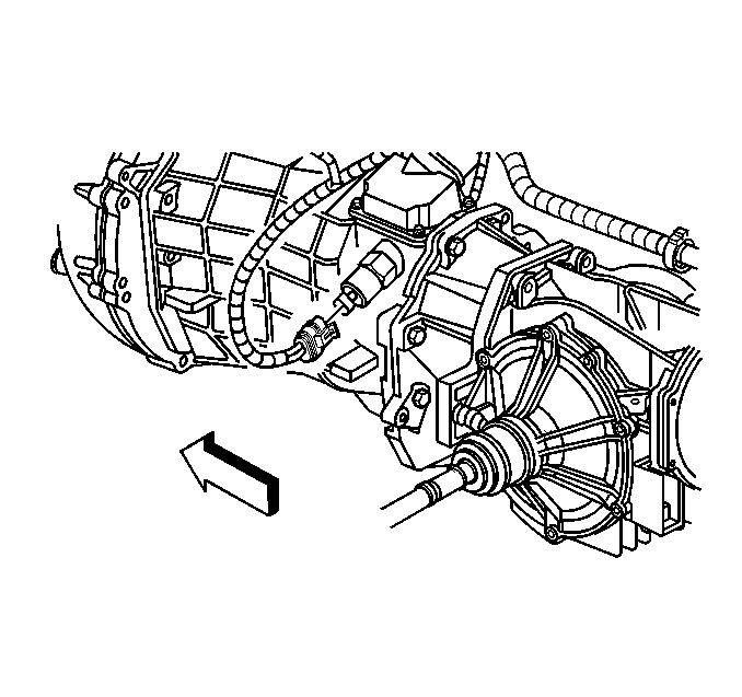
- Remove the 5 driveline support assembly to engine flywheel housing bolts.
- Carefully bend the wiring harness bracket away from the driveline toward the driveline tunnel wall in order to make a clear removal path for the driveline.
- Have an assistant insert a flat-bladed screwdriver, or similar tool, between the edge of the driveline support assembly and the engine flywheel housing, then begin to pry the driveline loose from the engine.
- Have an assistant guide the front of the driveline during the removal of the driveline from the vehicle.
- SLOWLY lower the driveline, while simultaneously adjusting the angle of tilt and pulling the driveline away from the engine UNTIL the propeller input shaft at the front of the driveline support assembly just clears the engine flywheel housing.
- SLOWLY lower the driveline completely out of the vehicle.
- Position the chainfall, or equivalent lifting device, in a way which will protect the rear exhaust hangers located on the driveline support assembly.
- Using the lifting device, raise the driveline to relieve the weight from the transmission jack.
- Disconnect the J 42055 from the transmission jack ONLY; the J 42055 will provide stability to the driveline components while working on a bench.
- Position the driveline on a workbench with the lifting device still attached.
- Support the driveline support assembly and the differential for additional balance.
- Remove the lifting device from the driveline.
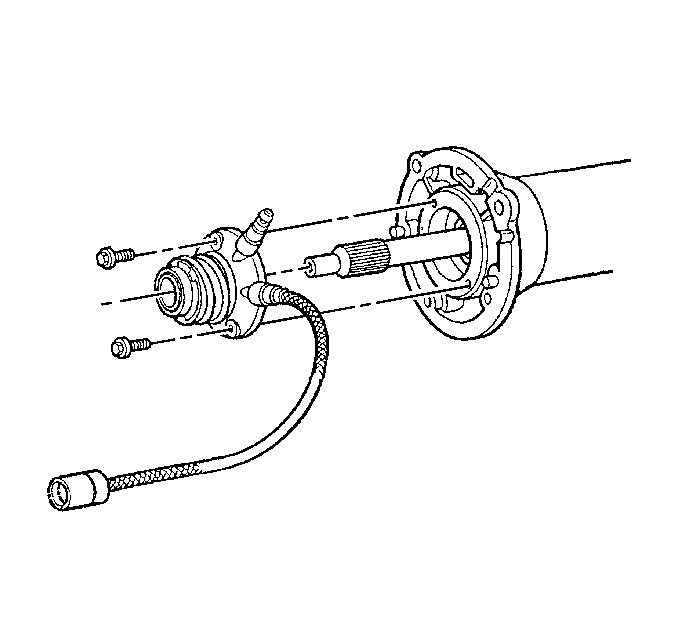
- Remove the clutch actuator cylinder mounting bolts.
- Remove the clutch actuator cylinder from the driveline support assembly.
- Remove the rear exhaust hanger mounting bolts.
- Remove the rear exhaust hangers from the driveline support assembly.
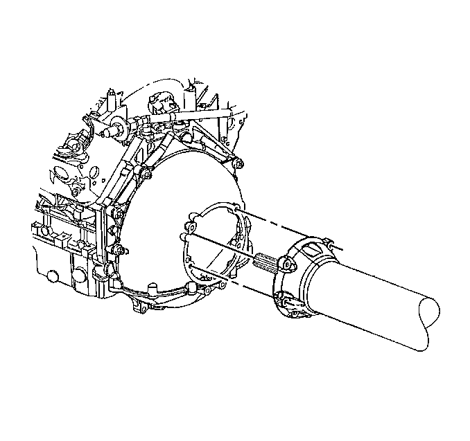
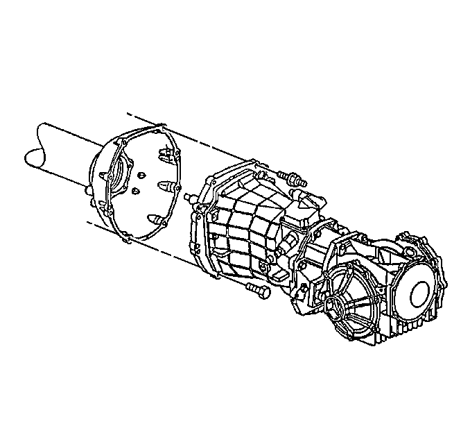
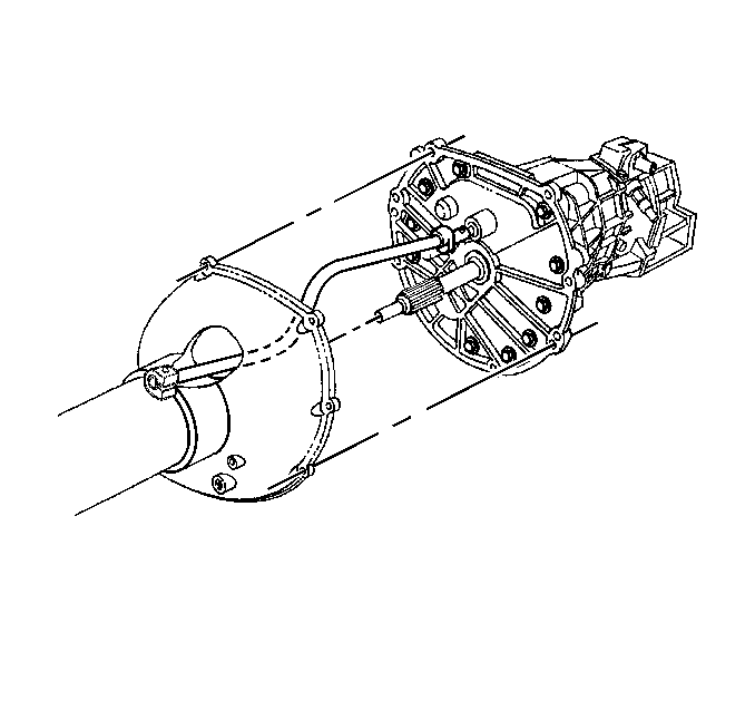
- Remove the transmission to driveline support assembly bolts/studs.
- Insert a flat-bladed screwdriver, or similar tool, between the edge of the driveline support assembly and the transmission, then begin to pry the driveline support assembly loose from the transmission.
- Slowly slide the driveline support assembly away from the transmission while guiding the transmission shift rod through the opening in the driveline support assembly.

The muffler assembly pipes toward the rear offer a good location to help support the wheel drive shafts.
The engine positive crankcase ventilation (PCV) pipes which route along the rear of the engine intake manifold (LS1 only) will likely contact the dash panel.
Important: The aid of an assistant will be necessary for the remaining steps.
Installation Procedure
Notice: When tilting down the rear of the driveline, insert a putty knife or similar tool between the shift control bracket on the driveline support assembly and the brake pipe retainer on the driveline tunnel wall to prevent damage.
Notice: Ensure that the clutch hydraulic hoses are positioned away from nearby vehicle components or vehicle damage may result.
- Slowly slide the driveline support assembly to the transmission, while guiding the shift rod through the opening in the driveline support assembly.
- Install the transmission to driveline support assembly bolts/studs.
- Install the rear exhaust hangers to the driveline support assembly.
- Install the rear exhaust hanger mounting bolts.
- Install the clutch actuator cylinder to the driveline support assembly.
- Install the clutch actuator cylinder mounting bolts.
- Loosely install a rubber band onto the transmission shift rod and position just behind the shift rod clamp.
- Using a piece of masking tape, or similar tape which can be easily broken, affix the transmission shift rod to the driveline support assembly and position the rod just to the outside of the mounting boss used for the shift control.
- Position the chainfall, or equivalent lifting device, in a way which will protect the rear exhaust hangers located on the driveline support assembly.
- Using the lifting device, raise the driveline off the workbench and position the driveline with the J 42055 onto a transmission jack.
- Connect the J 42055 to the transmission jack.
- Remove the lifting device from the driveline.
- Position the driveline under the vehicle.
- Begin to raise the driveline at the approximate angle used during removal.
- Position the wiring harness along the driveline support assembly and LOOSELY install the harness into the harness retaining slots.
- Have an assistant guide the front of the driveline so the propeller input shaft is just to the rear of the engine flywheel housing, then raise the driveline to the PROPER HEIGHT and the PROPER ANGLE to install to the engine.
- Have an assistant begin to insert the propeller input shaft into the clutch driven plate hub while maintaining the proper angle of the driveline; if necessary, use a screwdriver to rotate the shaft slightly to bring the splines into alignment.
- Insert a putty knife, or similar tool, between the edge of the shifter bracket on the side of the driveline support assembly and the brake pipe retainer on the wall of the driveline tunnel.
- SLOWLY seat the driveline to the engine flywheel housing while maintaining the proper angle of the driveline.
- Reposition the wiring harness bracket from near the driveline tunnel wall to align with the appropriate driveline support assembly bolt hole.
- Install the 5 driveline support assembly to engine flywheel housing bolts.
- Install the wiring harness to the wiring harness retainer along the top of the transmission.
- SLOWLY raise the driveline to approximately 51 mm (2 in) BELOW the final installed height.
- Connect the transmission fluid temperature sensor electrical connector, if equipped.
- Connect the gear select (skip shift) solenoid electrical connector.
- Connect the reverse lockout solenoid electrical connector.
- Connect the backup lamp switch electrical connector.
- Connect the wiring harness clip to the top of the differential.
- Connect the wiring harness retainer to the stud at the differential rear cover.
- Connect the VSS electrical connector.
- Slowly raise the driveline to final installation height.
- Remove the putty knife, if still in position.
- Remove the jack which supported the rear of the engine.
- Remove the tie-off retainers from the axle shafts.
- CAREFULLY align and seat the wheel drive shafts to the differential.
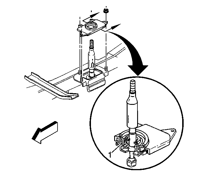
- Install the transaxle mount (2) to the differential.
- Install the transaxle mount nuts (1).
- With the aid of an assistant, begin to raise the rear suspension crossmember (still firmly attached to a transmission jack), until it contacts the vehicle frame rails.
- Guide the rear suspension crossmember alignment pins into the alignment holes in the vehicle frame rails, and guide the transaxle mount studs into the mounting holes in the crossmember, then raise the crossmember until it contacts the vehicle frame rails.
- Using ONLY HAND TOOLS, install NEW rear suspension crossmember mounting nuts.
- Remove the transmission jack from the rear suspension crossmember.
- Release the J 42055 from the transmission, then remove the J 42055 and transmission jack.
- Install the transaxle mount (2) to rear suspension crossmember nuts (3).
- Connect the wiring harness and brake pipe clip retainers to the rear suspension crossmember.
- Support the lower control arm with a straight jack.
- Connect the lower ball joint to the suspension knuckle. Refer to Knuckle Replacement.
- Install the shock absorber lower mounting bolt and nut. Refer to Shock Absorber Replacement.
- Connect the outer tie rod end to the suspension knuckle. Refer to Tie Rod Replacement.
- Remove the straight jack from the suspension control arm.
- Repeat steps 45 through 49 for the other side of the vehicle.
- Install the rear transverse spring. Refer to Rear Transverse Spring Replacement.
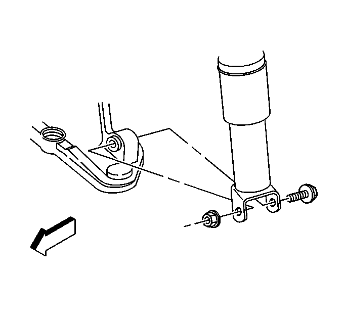
- Carefully pull the wiring harness down into the L-shaped brackets along the driveline support assembly, align the harness retainer (locator) (1) to the hole in the forward bracket, then secure in place.
- Install the hose retaining clip (1).
- Connect the clutch actuator cylinder hose (3) to the clutch master cylinder hose (2).
- Inspect the clutch hydraulic hoses for twists or kinks.
- Install the clutch actuator cylinder hose to the hose retaining clip, below the power brake booster.
- Install the floor panel tunnel reinforcement. Refer to Floor Panel Tunnel Panel Reinforcement Replacement.
- Remove the tie-off retainers from the muffler assemblies.
- Install the catalytic converters. Refer to Catalytic Converter Replacement - Left Side and Catalytic Converter Replacement - Right Side.
- Install the rear tire and wheel assemblies. Refer to Tire and Wheel Removal and Installation.
- Lower the vehicle.
- Connect the clutch master cylinder pushrod to the clutch pedal.
- Install the clutch master cylinder pushrod retainer.
- Install the left I/P lower insulator panel. Refer to Instrument Panel Insulator Panel Replacement.
- Grasp the transmission shift rod and pull up to break the masking tape installed earlier to maintain position during installation.
- Stretch the rubber band, while still installed onto the transmission shift rod, over the rear stud on top of the driveline tunnel to aid in shift control installation.
- Install the shift control assembly. Refer to Shift Control Assembly Replacement.
- Break and remove the rubber band.
- Install the shift control closeout boot.
- Install the shift control closeout boot retaining nuts.
- Install the I/P accessory trim plate. Refer to Instrument Panel Accessory Trim Plate Replacement.
- Install the shift control boot over the shift control lever.
- Align the shift control boot to the I/P accessory trim plate opening, then press to lock the boot retaining tabs.
- Adjust the shape of the boot for appearance, if necessary.
- Screw the shift control knob onto the shift control lever until the knob bottoms out.
- Unscrew the shift control knob just enough to align the retainer slot with the slot on the shift control lever.
- Install the shift control knob retainer (1) into the slots and seat fully.
- Install the shift control knob button.
- Install the console. Refer to Console Replacement.
- Connect the negative battery cable.
- Program the transmitters. Refer to Transmitter Programming.
- Bleed the clutch hydraulic system. Refer to Hydraulic Clutch Bleeding.
Notice: Refer to Fastener Notice in the Preface section.
Tighten
Tighten the transmission to driveline support assembly bolts/studs to 50 N·m (37 lb ft).
Tighten
Tighten the rear exhaust hanger mounting bolts to 50 N·m (37 lb ft).
Tighten
Tighten the clutch actuator cylinder mounting bolts to 12 N·m (106 lb in).
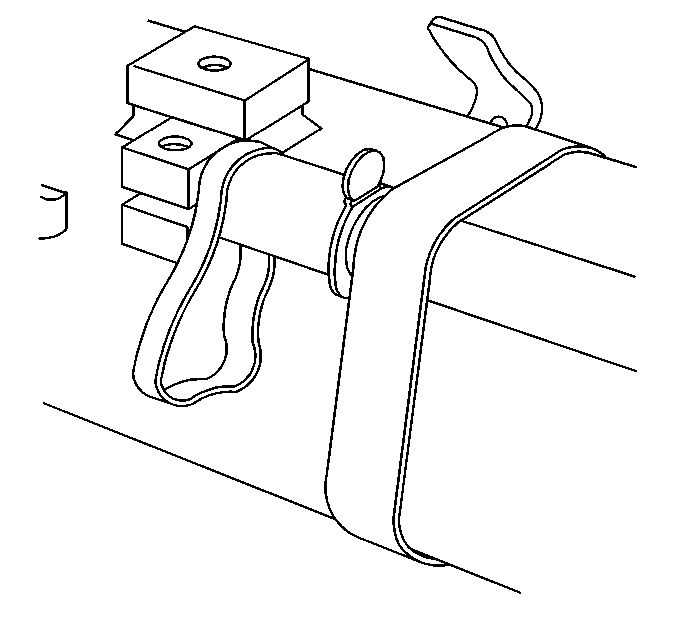
The rubber band will be used to aid in installing the shift control rod after the driveline has been installed.
The tape is intended to keep the shift control rod in position, and to aid in shift control rod installation.
Important: The aid of an assistant will be necessary for the following steps until the driveline is installed into the vehicle.
Tighten
Tighten the driveline support assembly to engine flywheel housing bolts to 50 N·m (37 lb ft).
Tighten
Tighten the transaxle mount nuts to 50 N·m (37 lb ft).
Tighten
Tighten the rear suspension crossmember mounting nuts to 110 N·m (81 lb ft).
Tighten
Tighten the transaxle mount to rear suspension crossmember nuts to 50 N·m (37 lb ft).
Important: DO NOT rely on an audible click or a visual verification of the clutch hydraulic hose quick connect fitting connection.
Push together the clutch hydraulic hose quick connect fittings, then pull back on the fittings to verify engagement.
Ensure the closeout boot fully seats to the shift control lever seal and the base of the shift control assembly (1).
Tighten
Tighten the shift control closeout boot retaining nuts to 12 N·m (106 lb in).
Tighten
Tighten the negative battery cable bolt to 15 N·m (11 lb ft).
