Rear Bearing Housing Assembly - Manual Transmission
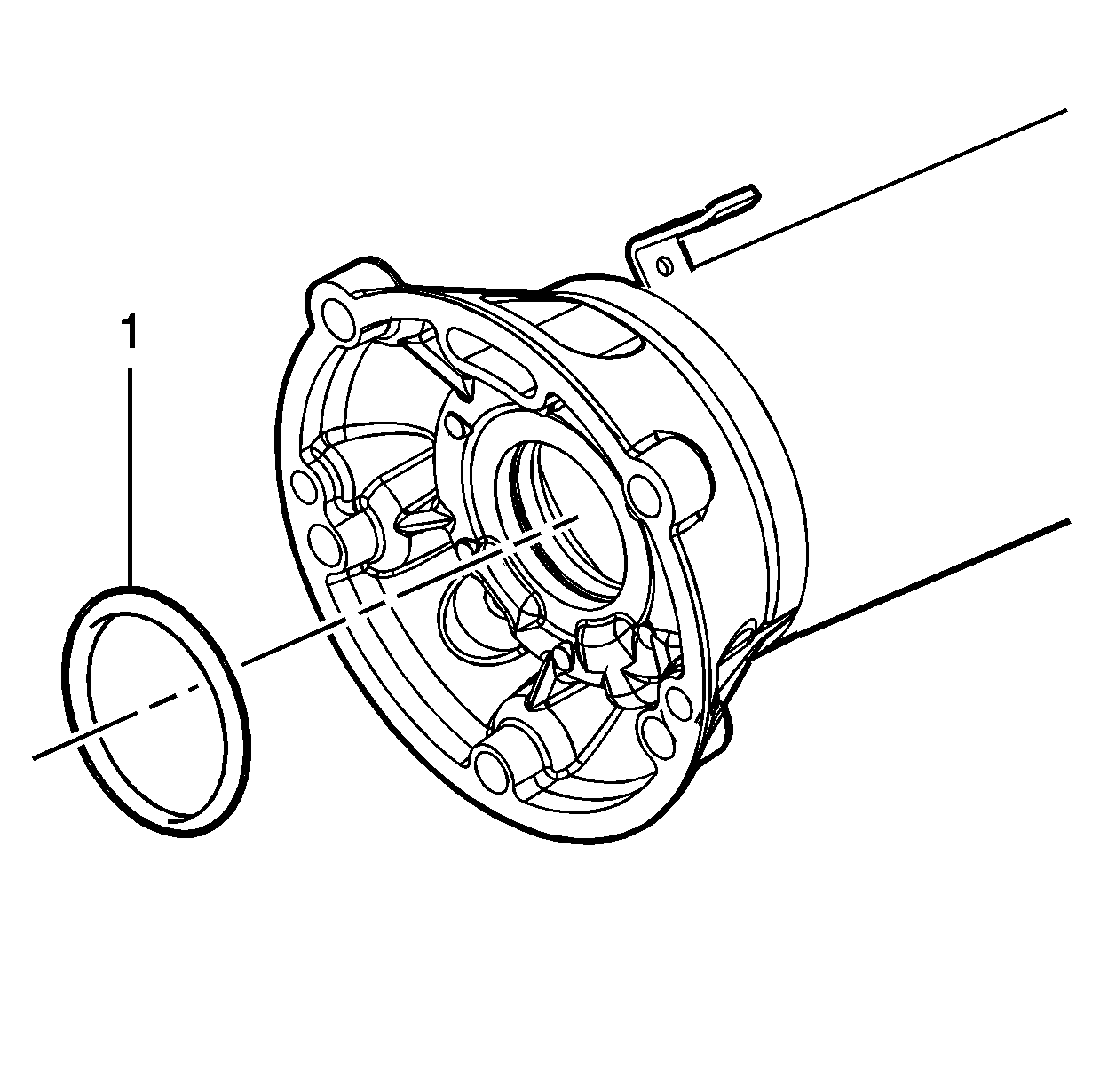
- Install the wave washer (1) into the rear bearing housing.
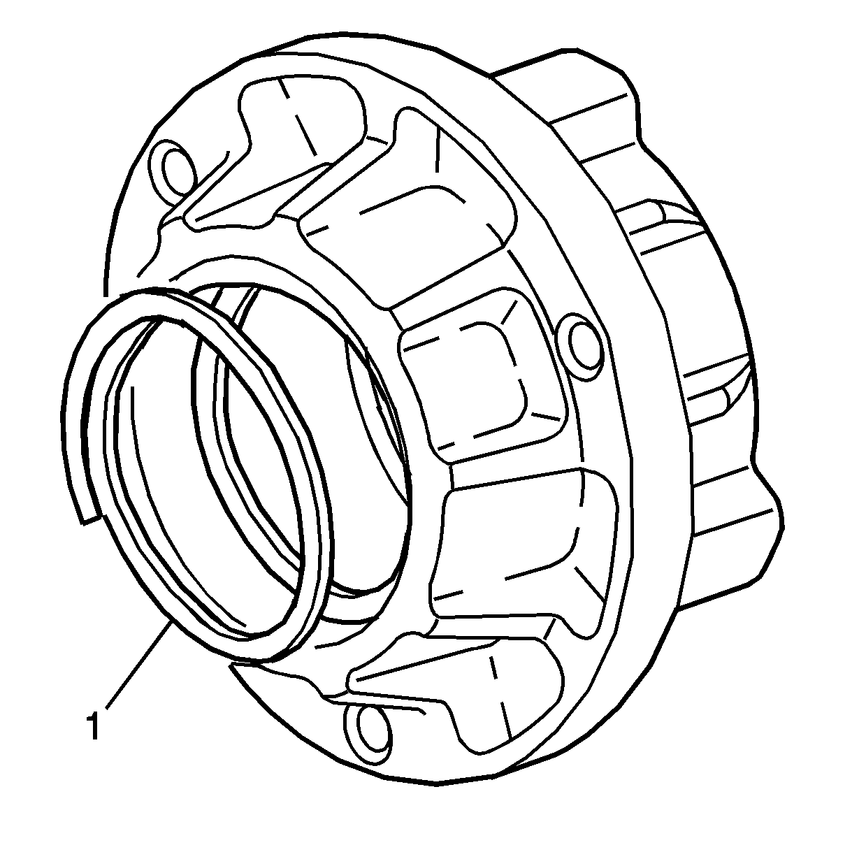
- Lubricate the NEW rear bearing housing O-rings (1) with clean engine oil.
- Install the O-rings into the rear bearing housing.
- Position the rear bearing housing (2) into a press in order to install the bearing (1).
- Install the bearing (1) into the housing.
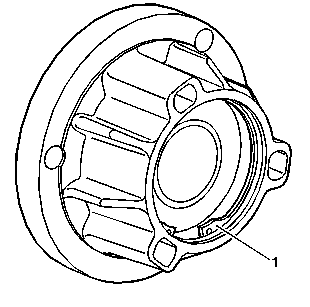
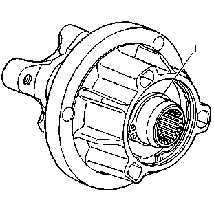
- Install the snap ring (1) into the rear bearing housing.
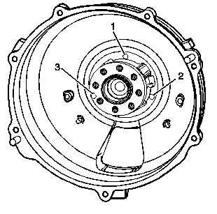
- Install the transmission input shaft bushing (2) and propeller shaft bushing (1) into the hub, if required.
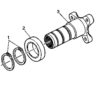
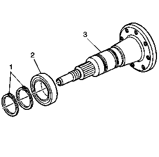
- Install the bearing (2) and snap rings (1) onto the hub (3).
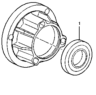
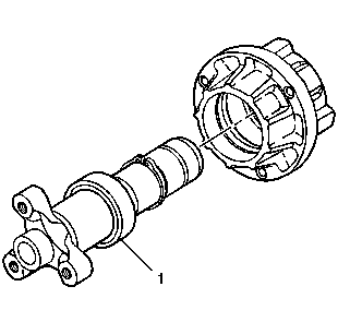
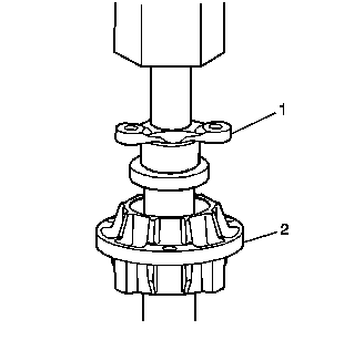
- Install the hub (1) into the rear bearing housing.
- Press the hub, with bearing (1), into the housing (2). Support the inner race of the housing bearing when assembling the components.
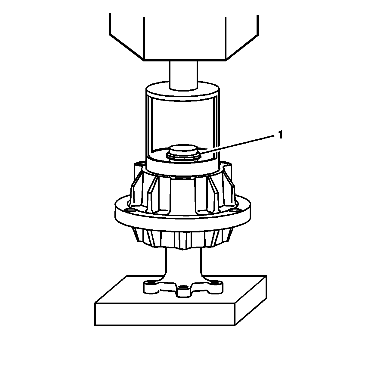
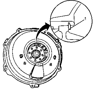
- Position the bearing housing into a press. Apply pressure to the housing and compress the wave washer in order to install the snap ring (1).
- Install the snap ring (1) onto the hub.
Important: Do not separate the input shaft, propeller shaft, couplings, or bearing housing assembly, unless required. These components are balanced as an assembly. Disassembly and improper reassembly of the components may cause vehicle driveline vibration.
If the input shaft, couplings, propeller shaft, or bearing housing assembly must be separated, the components must be marked prior to disassembly. During assembly, the components must be returned to their original position and location.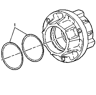
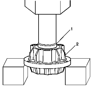
Important: Press only on the outer race of the bearing.
Important: Install the propeller shaft bushing into hub with the smaller opening of the bushing positioned away from the hub.
Rear Bearing Housing Assembly - Automatic Transmission
- Lubricate the NEW rear bearing housing O-rings (1) with clean engine oil.
- Install the O-rings into the rear bearing housing.
- Position the rear bearing housing (2) into a press in order to install the bearing (1).
- Install the bearing (1) into the housing.
- Install the snap ring (1) into the rear bearing housing.
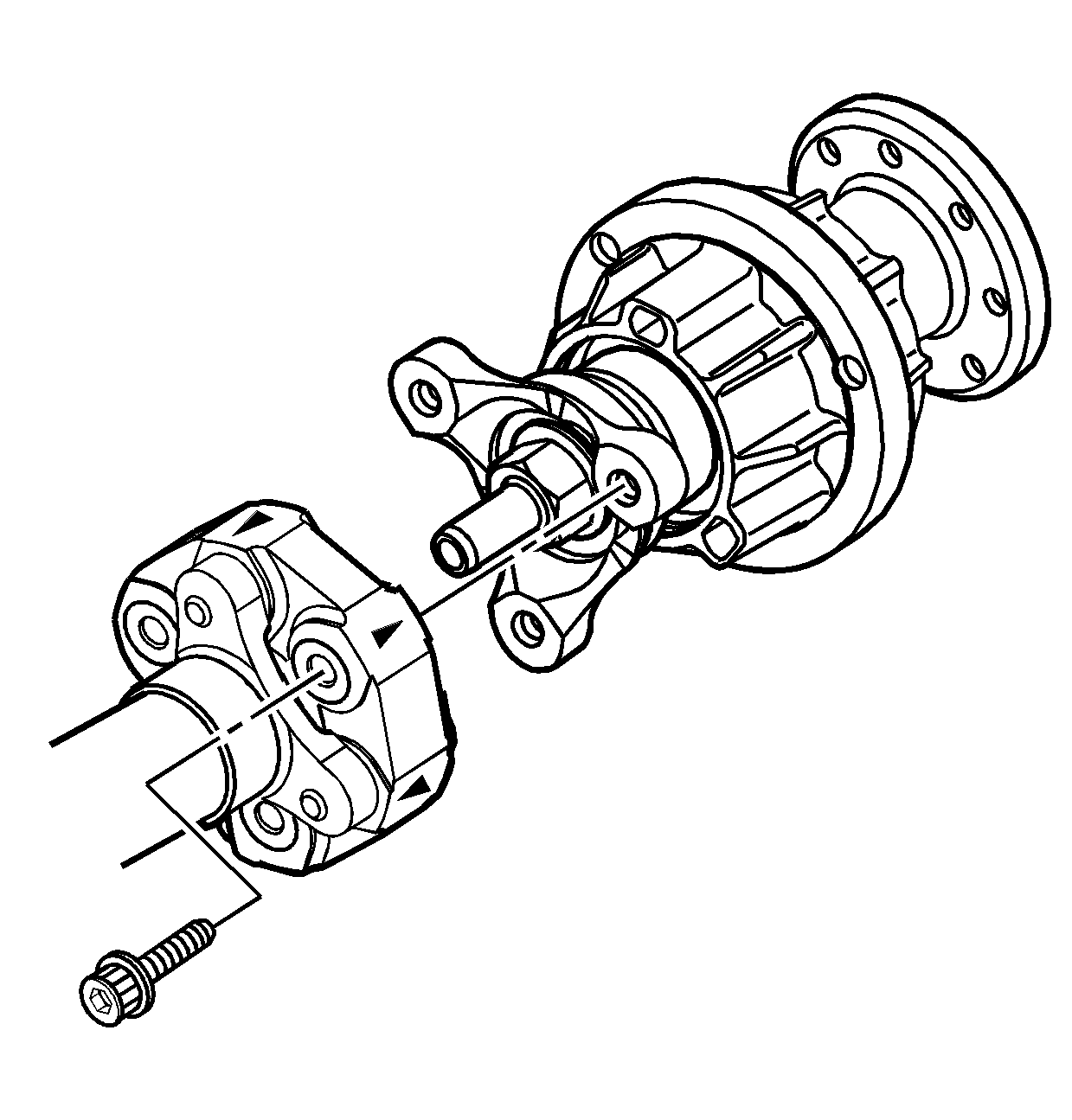
- Install the bearing (2) and snap rings (1) onto the flex plate spindle (3).
- Install the flex plate spindle, with bearing, into the rear bearing housing.
- Press the flex plate spindle, with bearing (1), into the housing (2). Support the inner race of the housing bearing when assembling the components.
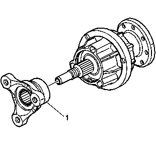
- Install the hub (1) onto the flex plate spindle. Align the marks on the flex plate spindle and hub for proper assembly.
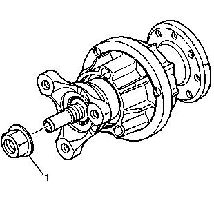
- Apply threadlock GM P/N 12345382 (Canadian P/N 10953489), or equivalent, to the threads of the spindle.
- Install the nut (1) to the flex plate spindle.
Important: Press only on the outer race of the bearing.
Notice: Refer to Fastener Notice in the Preface section.
Tighten
Tighten the spindle nut to 90 N·m (66 lb ft).
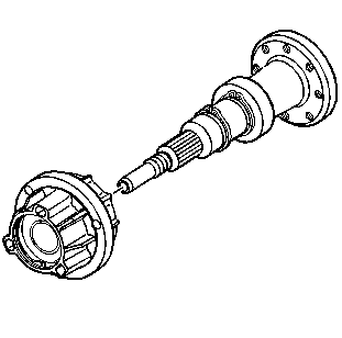
Propeller Shaft Installation
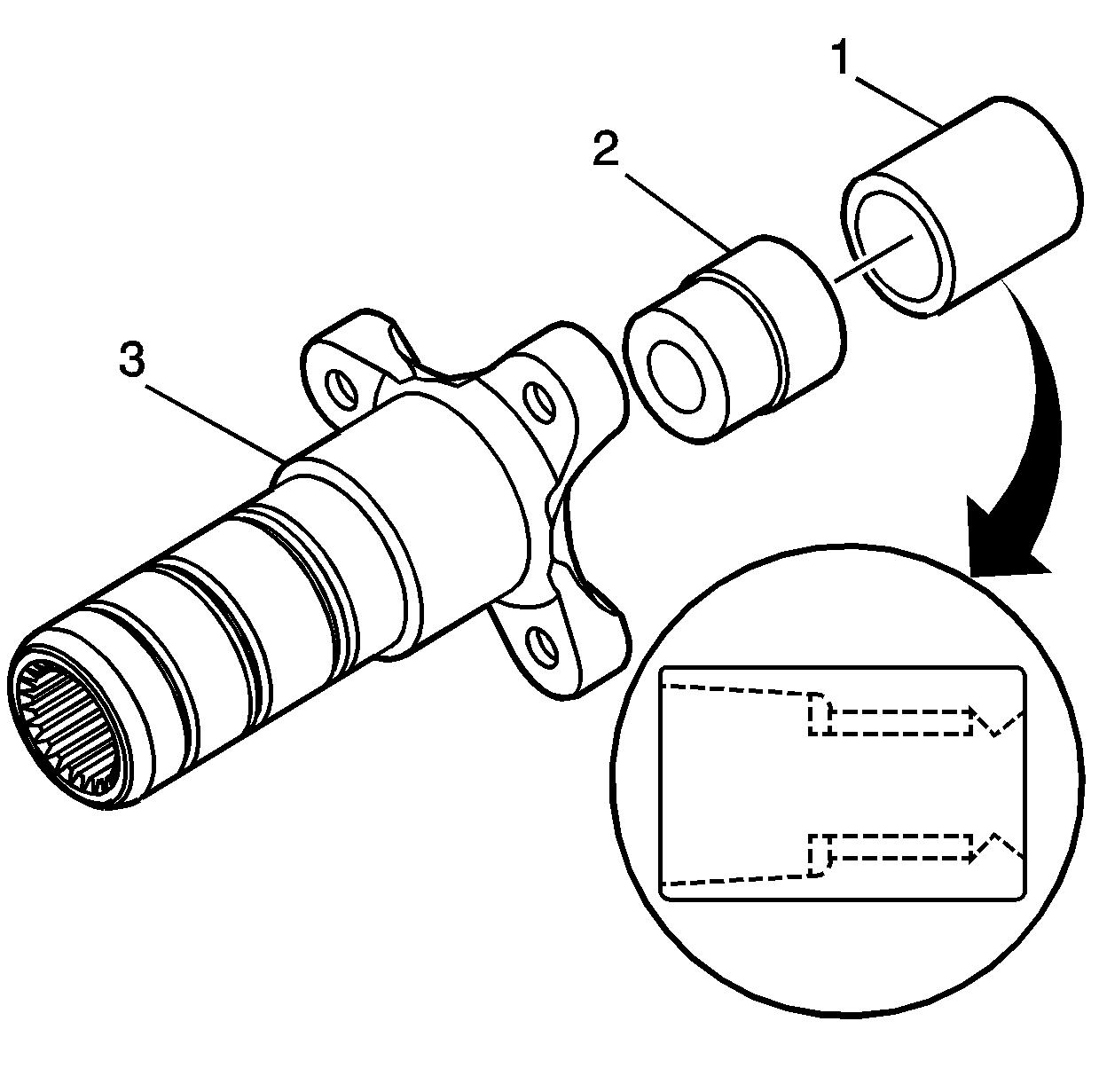
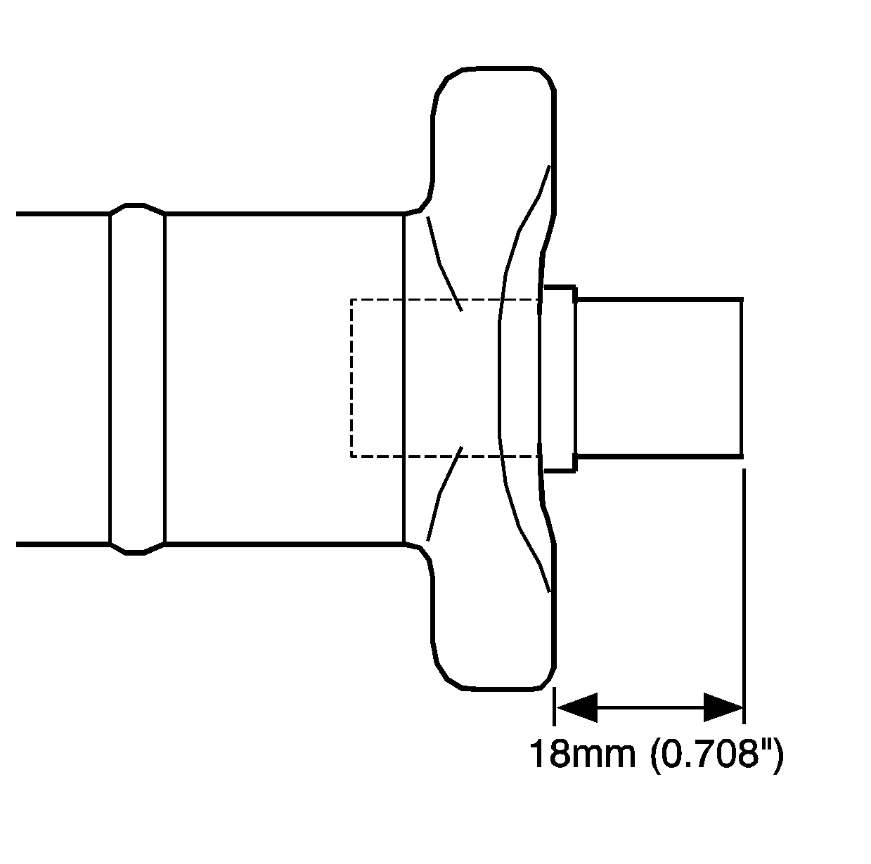
- Install a NEW bushing (1) into the automatic transmission propeller shaft, if required.
- Inspect the bushing for proper installation. A properly installed bushing will protrude 18 mm (0.708 in) from the face of the hub.
- Apply threadlock GM P/N 12345382 (Canadian P/N 10953489), or equivalent, to the threads of the coupling bolts.
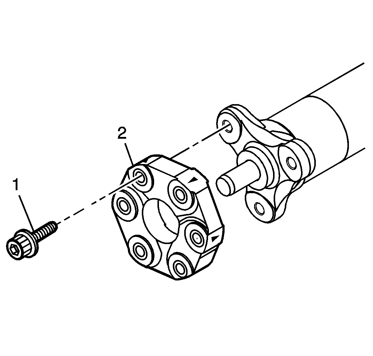
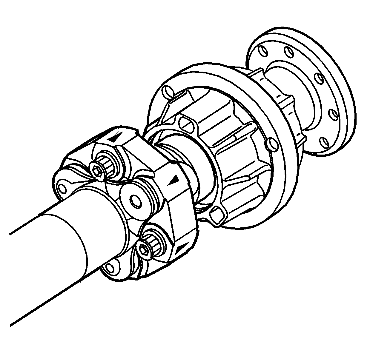
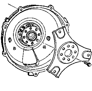
- Install the rear coupling (1), bolts (2), and washers to the propeller shaft.
- Install the rear bearing housing assembly, bolts, and washers to the rear coupling.
- Install the front coupling (2), bolts (1), and washers to the propeller shaft.
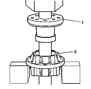
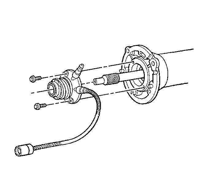
- Install the bearing (1) onto the input shaft.
- Install the snap ring (2) into the groove of the input shaft.
- Install a NEW slinger washer (1) onto the input shaft.
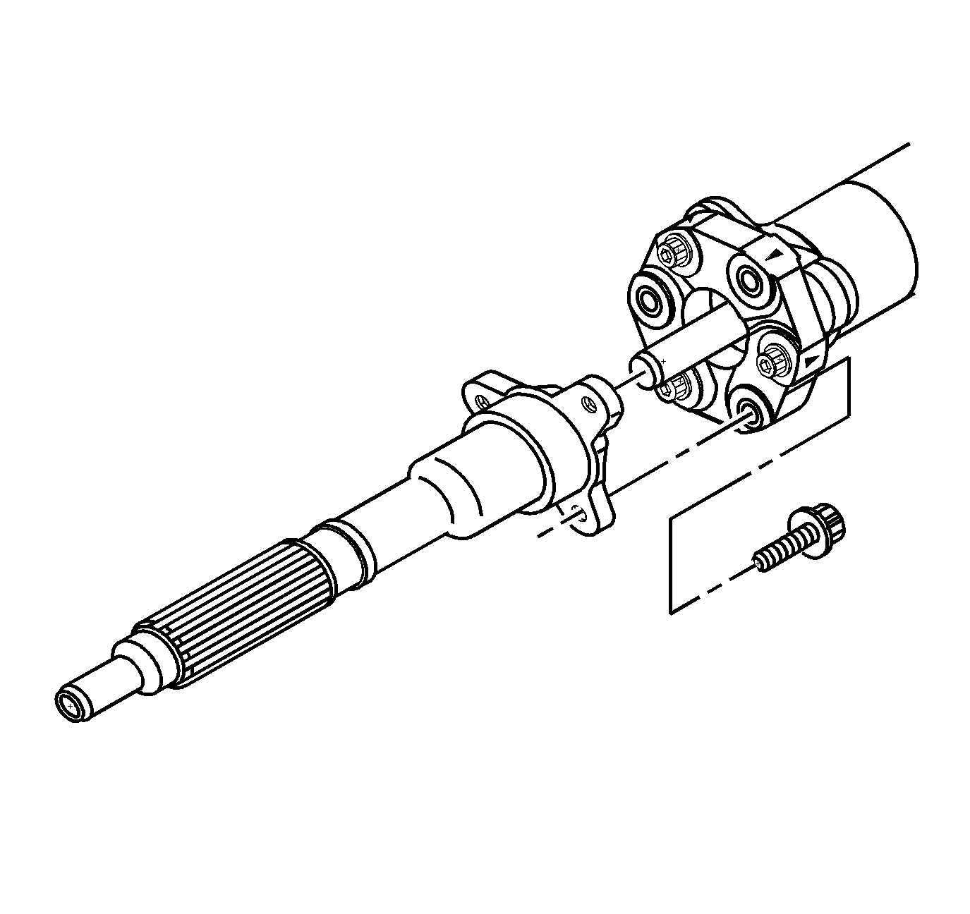
- Install the input shaft, bolts, and washers to the coupling.
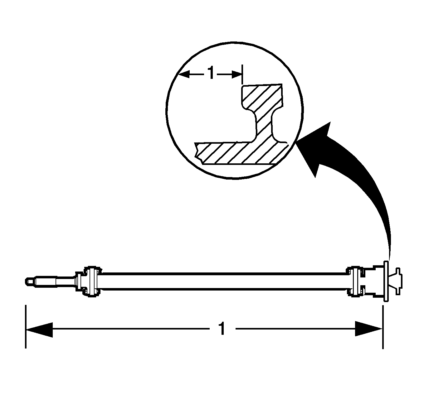
- Measure the distance (1) from the end of the input shaft to the flange on the bearing housing - automatic transmission. Record the amount as distance 1.
- Measure the distance (2) from the driveline tube front bellhousing flange to the bearing housing flange - automatic transmission. Record this as distance 2.
- Subtract the distance 2 from distance 1.
- Record the computation as distance 3.
- Lubricate the NEW driveline tube O-ring (1) with clean engine oil.
- Install the O-ring into the front of the driveline tube.
- Install the propeller shaft assembly into the driveline tube.
- Install the rear bearing housing bolt hole plugs (1-3).
- Install the snap ring (1) into the driveline tube. The beveled edge of the snap ring faces the rear of the driveline tube assembly and will seat completely into the groove of the housing.
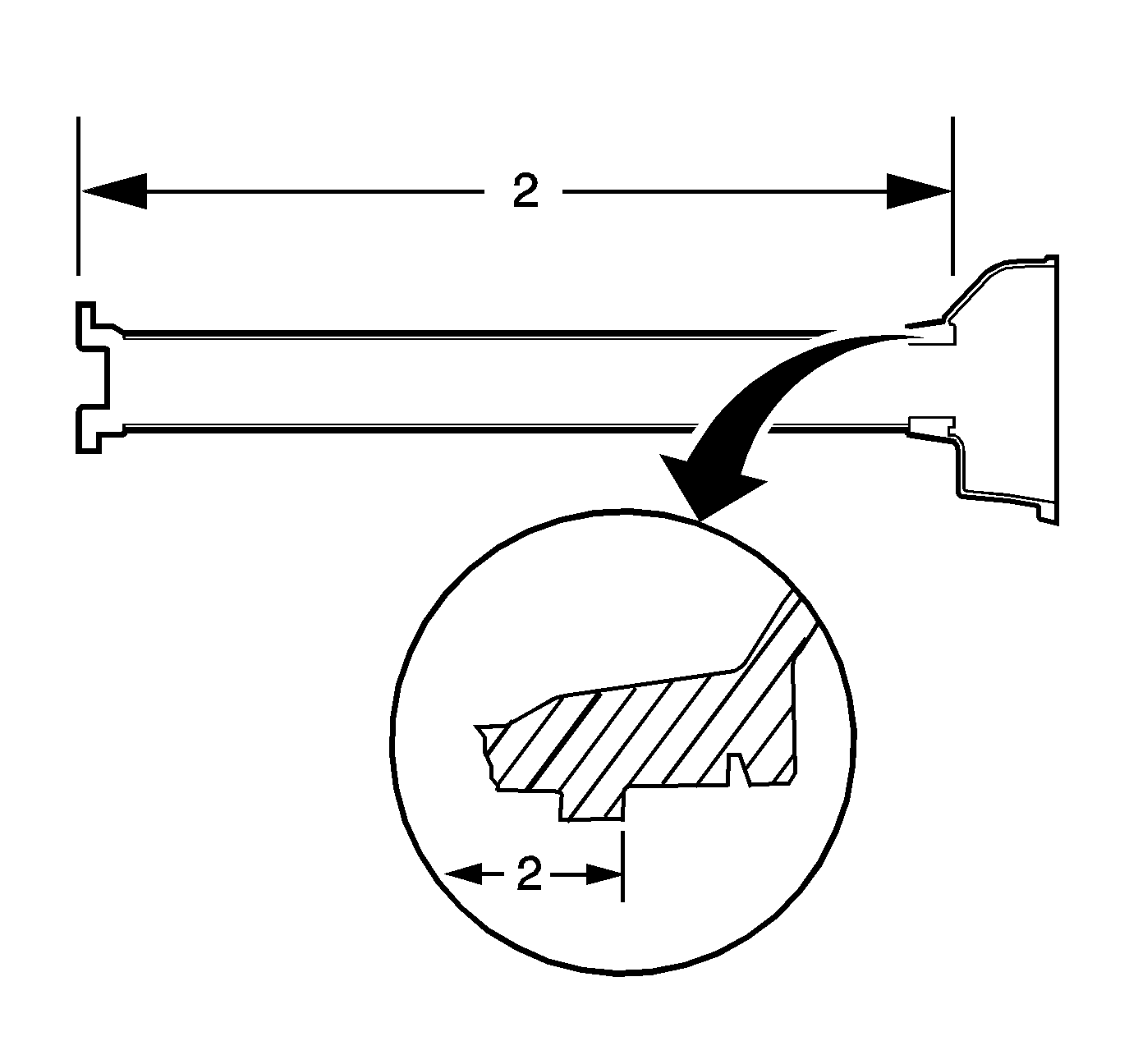
- Measure the distance from the end of the input shaft to the driveline tube front bell housing flange - automatic transmission.
- Install the flex plate and bolts - automatic transmission.
- Install the clutch actuator and bolts - manual transmission.
Important: Install the propeller shaft bushing into hub with the smaller opening of the bushing positioned away from the flange.
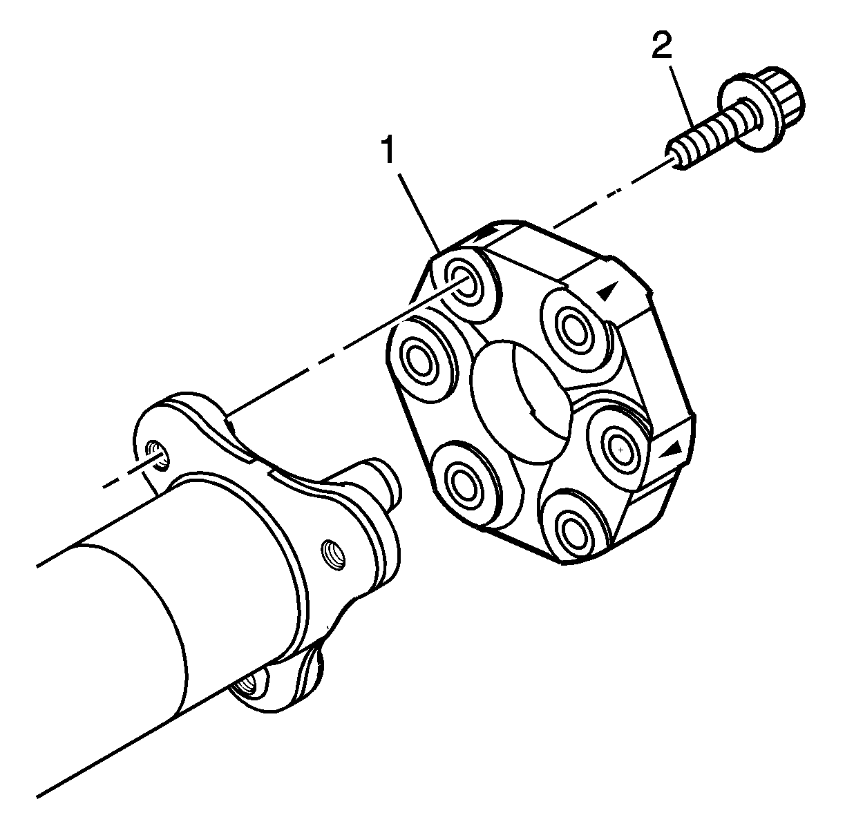
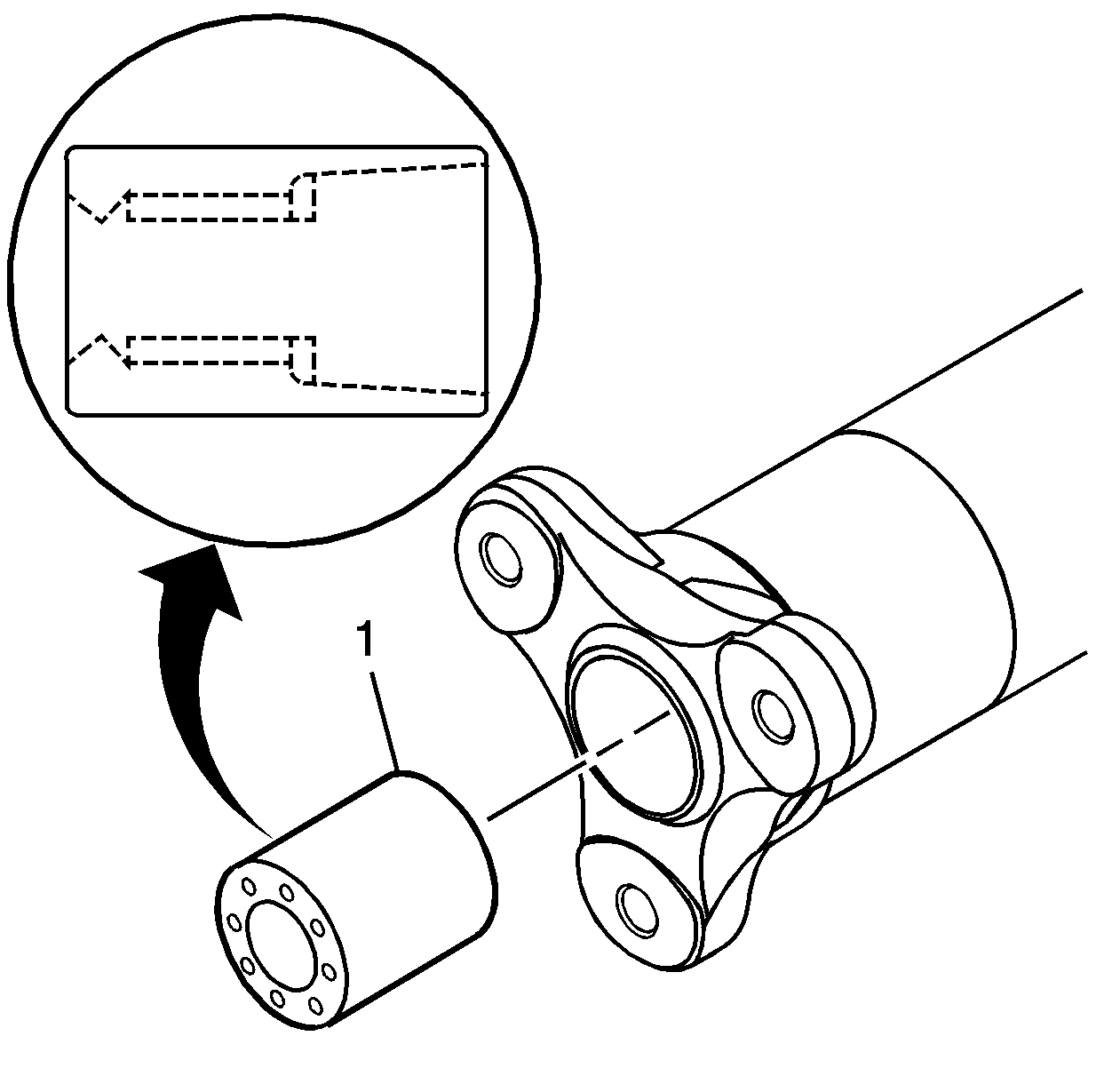
Important: If the coupling orientation mark has been lost during the cleaning or disassembly process, the coupling MUST be installed with the directional arrow pointed toward the flange to which it mounts.
Tighten
Tighten the coupling bolts to 90 N·m (66 lb ft).
Important: If the coupling orientation mark has been lost during the cleaning or disassembly process, the coupling MUST be installed with the directional arrow pointed toward the flange to which it mounts.
Tighten
Tighten the coupling bolts to 90 N·m (66 lb ft).
Tighten
Tighten the coupling bolts to 90 N·m (66 lb ft).
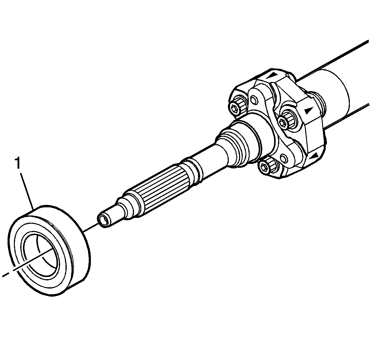
Install the bearing until completely seated against the flange of the input shaft.
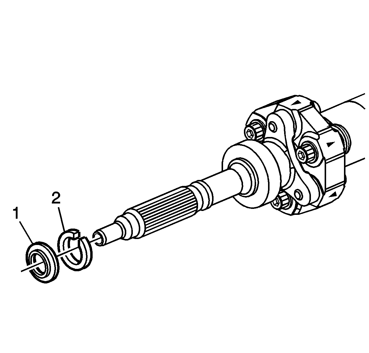
A properly installed slinger washer will have a gap of 1.5-2.5 mm (0.050-0.098 in) between the washer and the bearing face.
Tighten
Tighten the coupling bolts to 90 N·m (66 lb ft).
During installation, lift the front of the input shaft to avoid damage to the slinger washer. Using a punch, tap evenly on the flat flange area of the rear bearing housing and install the assembly completely into the tube.
Important: The propeller shaft assembly must be checked for proper installation into the driveline tube - automatic transmission. When the propeller shaft assembly is installed into the driveline tube, the couplings may compress and not properly position the input shaft.
The actual distance must be equal to or within 2 mm (0.079 in) of the recorded dimension 3.
| 20.1. | If the actual distance is not within specifications, use a heat gun and heat the outside of the driveline support tube at the front bearing location. |
| 20.2. | Tap on the rear of the propeller shaft assembly or pull on the input shaft until the shaft has reached the proper position. |
Tighten
Tighten the flex plate bolts to 50 N·m (37 lb ft).
Tighten
Tighten the clutch actuator bolts to 12 N·m (106 lb in).
