Front Rail End Replacement Corvette
Tools Required
J 42058 Frame Adapter Clamp
Removal Procedure
The service assemblies for the left and the right front frame rails are pre-sleeved, mild steel, hydro-formed parts.
Caution: Refer to Approved Equipment for Collision Repair Caution in the Preface section.
- Disable the SIR system. Refer to SIR Disabling and Enabling .
- Disconnect the negative battery cable. Refer to Battery Negative Cable Disconnection and Connection .
- Remove all related panels and components.
- Remove the front impact bar. Refer to Front Bumper Impact Bar Replacement .
- Note the location and remove the sealers and anti-corrosion materials from the repair area. Refer to Anti-Corrosion Treatment and Repair .
- Repair as much of the damage as possible to the factory specifications.
- Use J 42058 to secure the vehicle if pulling and straightening are required.
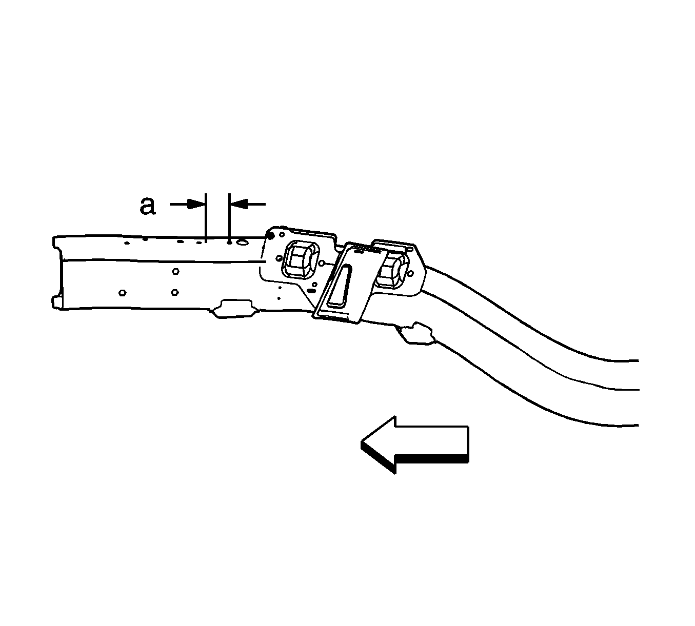
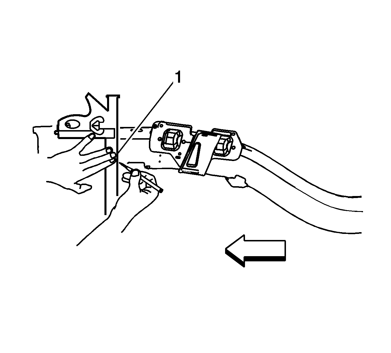
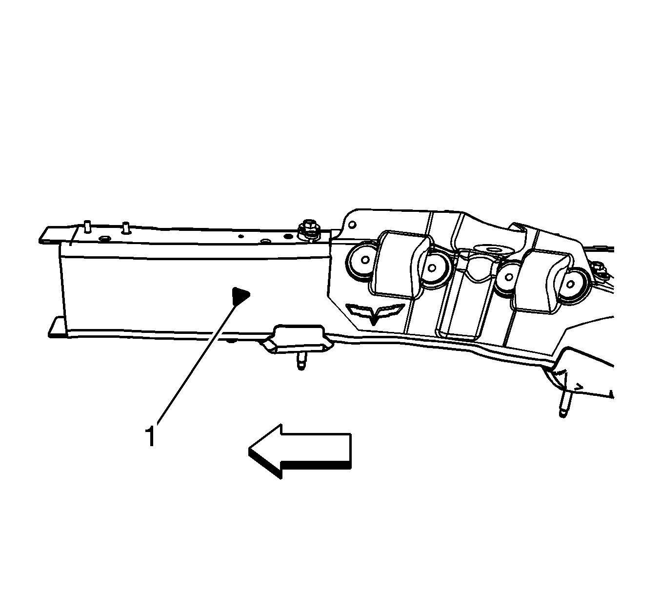
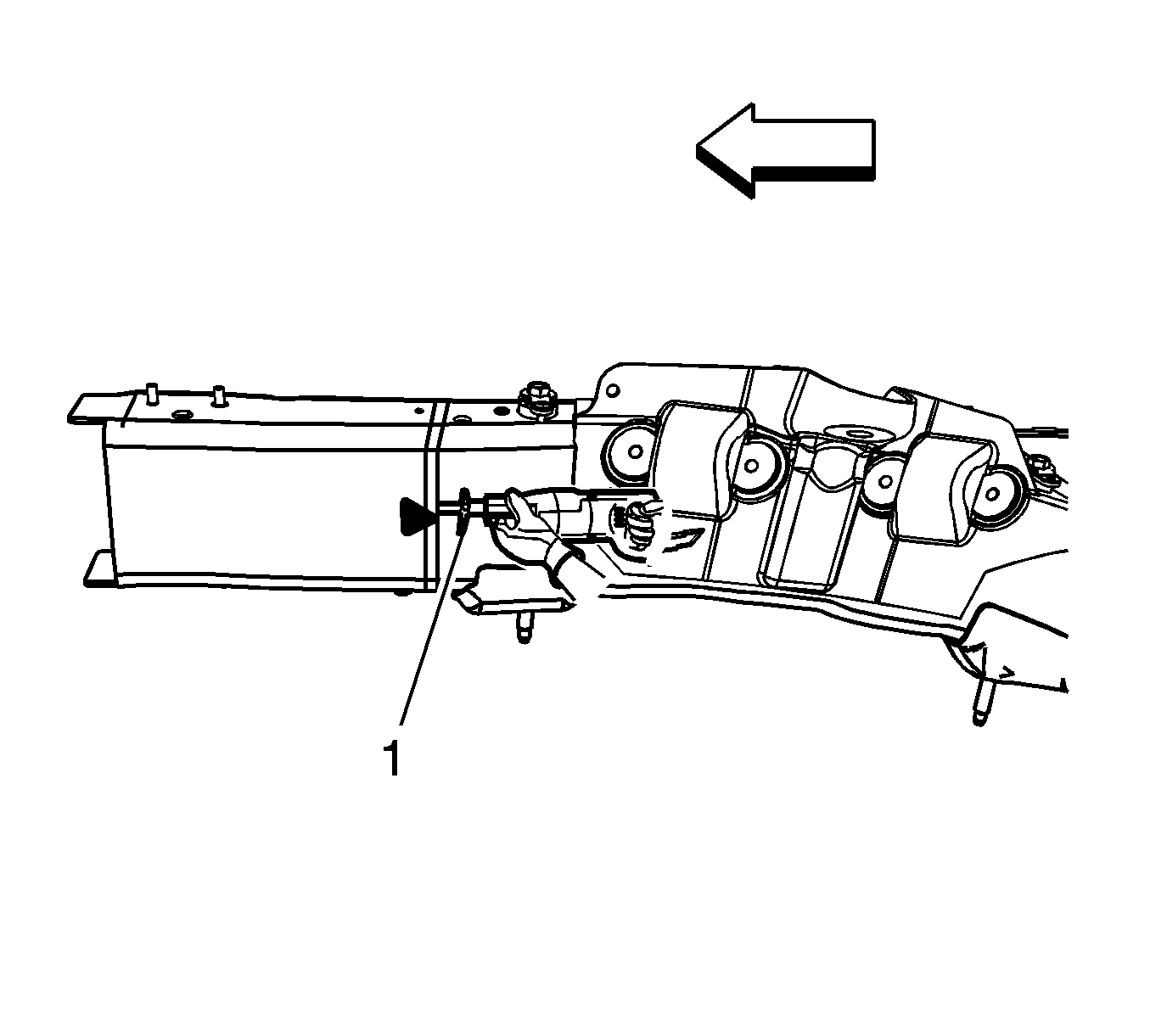
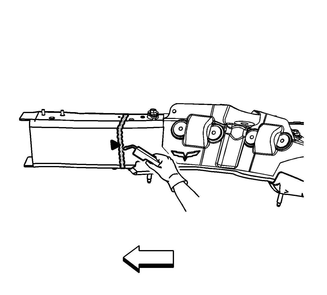
- Determine the sectioning joint location from the center of the rear upper radiator support bolt (1).
- Measure 67 mm (2 5/8 in) (a) forward from the center of the rear upper radiator support bolt.
- Mark the top of the frame rail at the sectioning location.
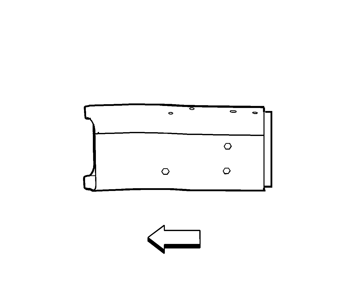
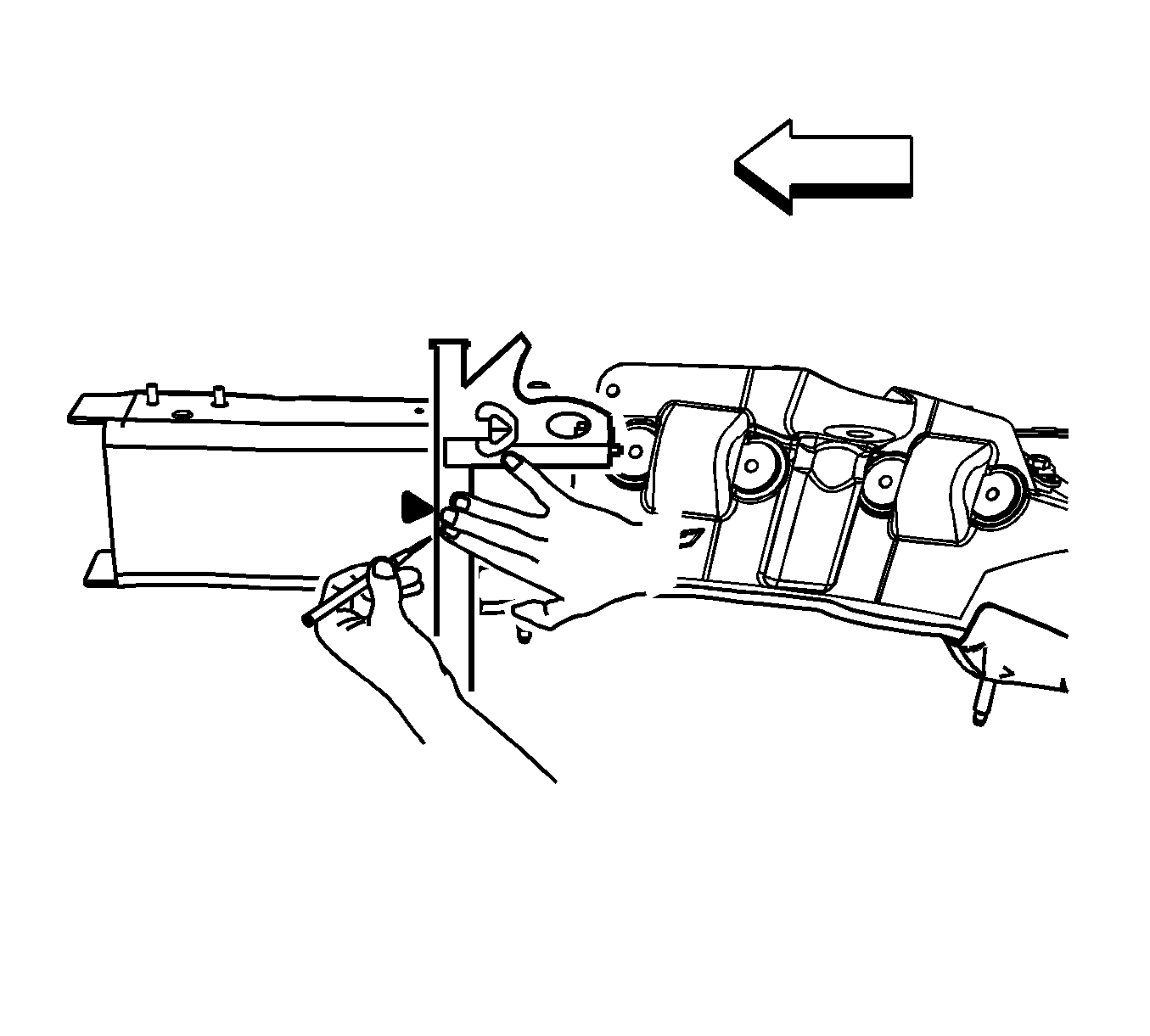
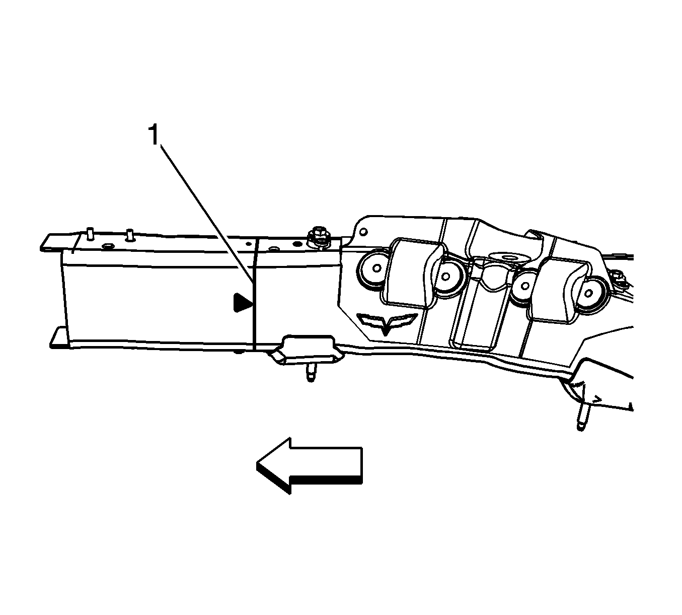
- At the mark align a sliding square or similar tool (1) square to surface to the vertical walls of the frame rail.
- Scribe a line to both sides of the frame rail.
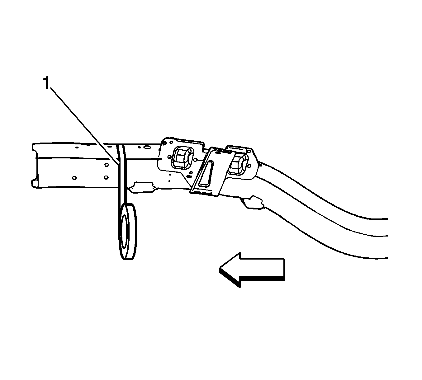
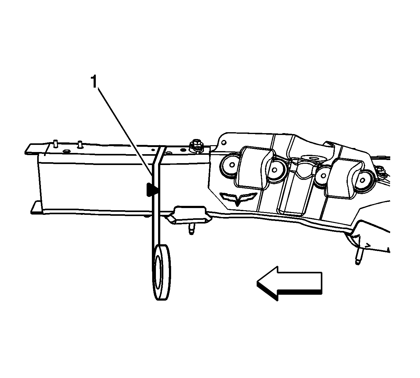
- Apply masking tape (1) to the scribe line completely around the frame rail.
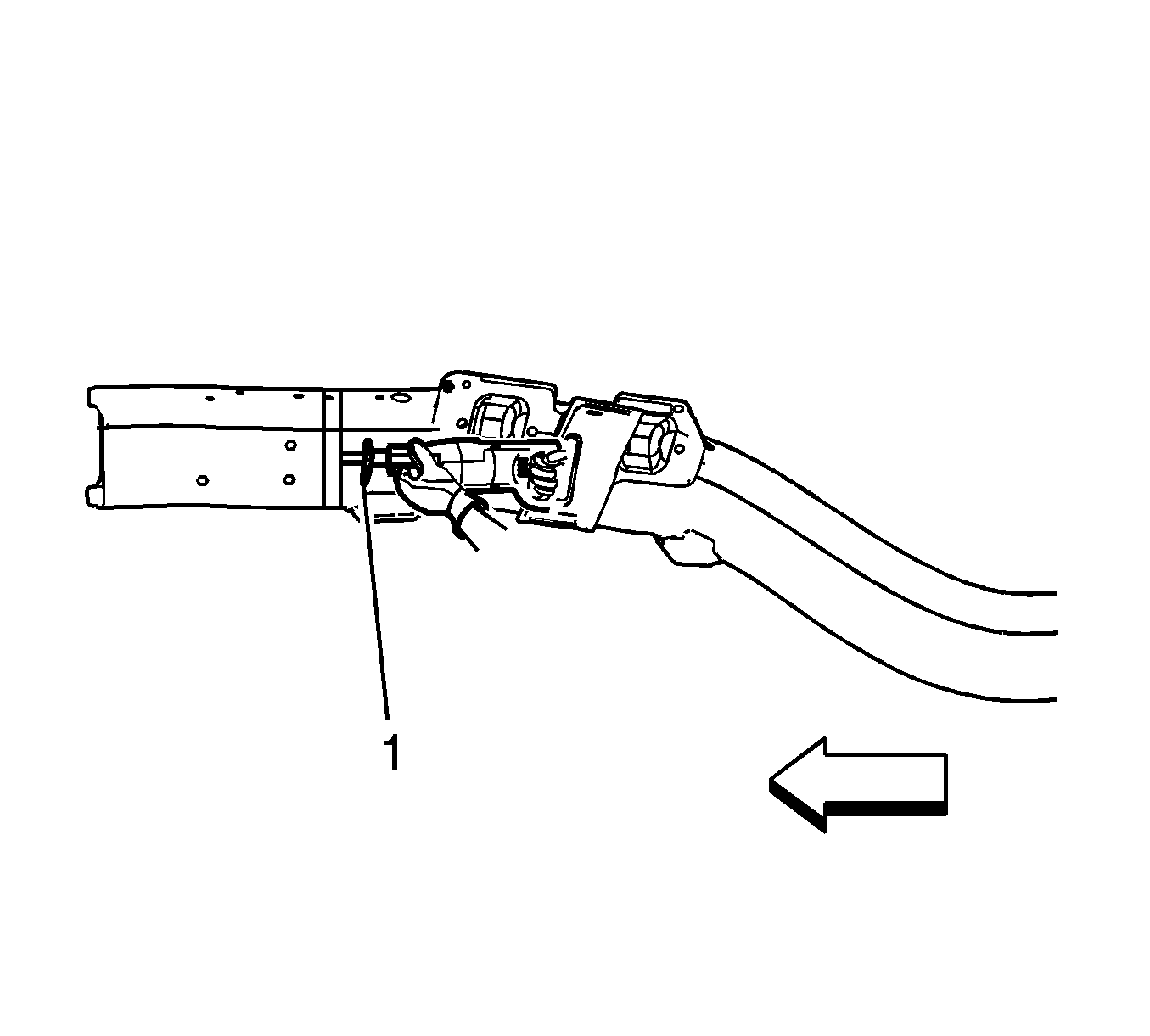
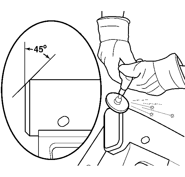
- Cut the frame rail at the rear edge of the tape line using a reciprocating saw or equivalent tool (1).
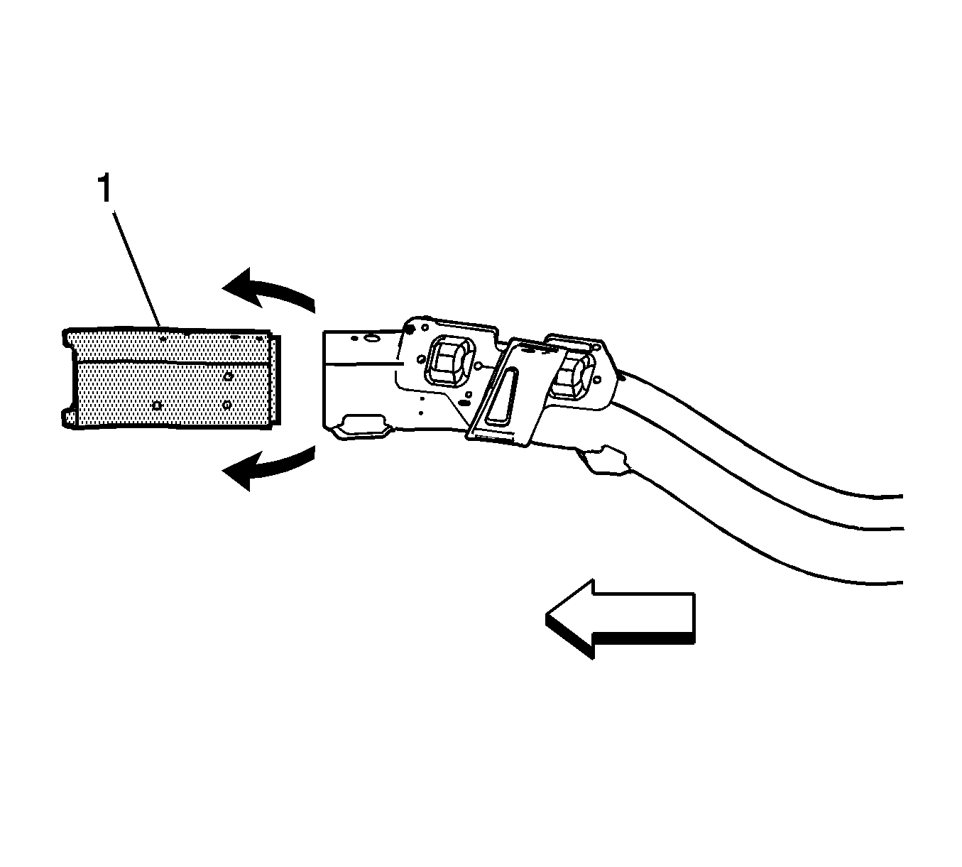
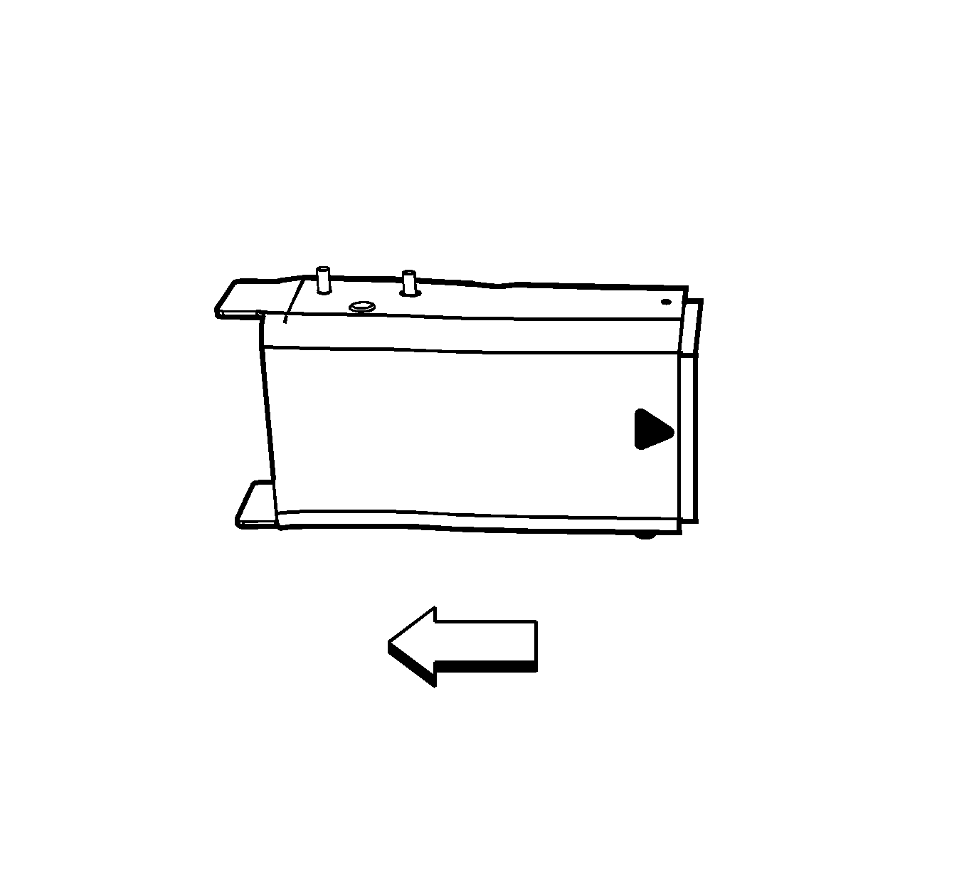
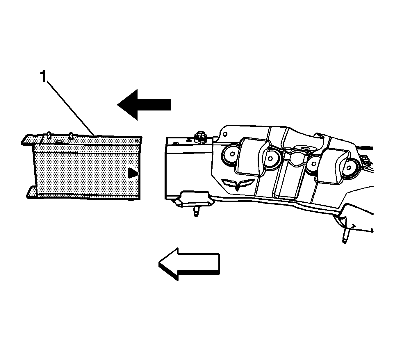
- Remove the damaged frame rail end section (1).
Caution: Refer to Collision Sectioning Caution in the Preface section.
Installation Procedure
- Grind the existing frame rail sectioning location to a 45 degree angle.
- Clean and prepare all of the welded mating surfaces.
- Apply GM-approved Weld-Thru Coating or equivalent to all mating surfaces. Refr to Anti-Corrosion Treatment and Repair .
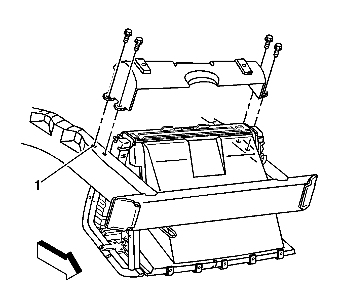
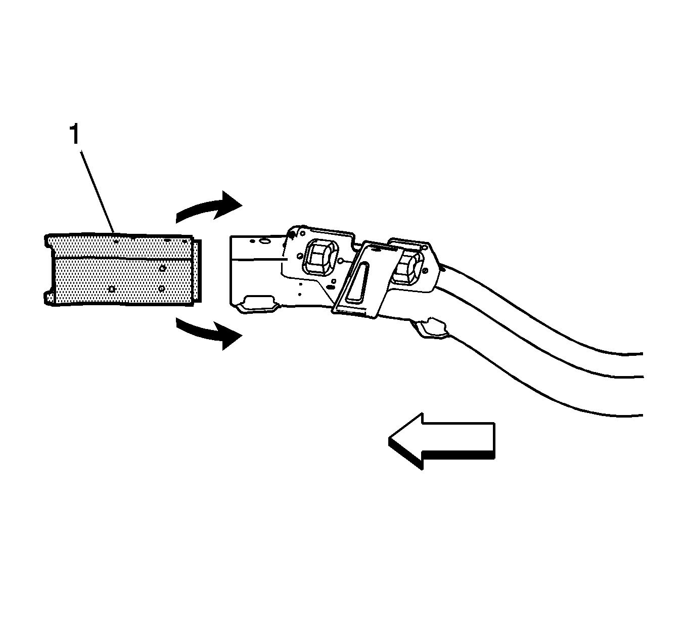
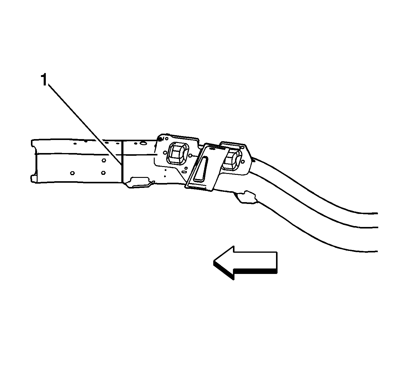
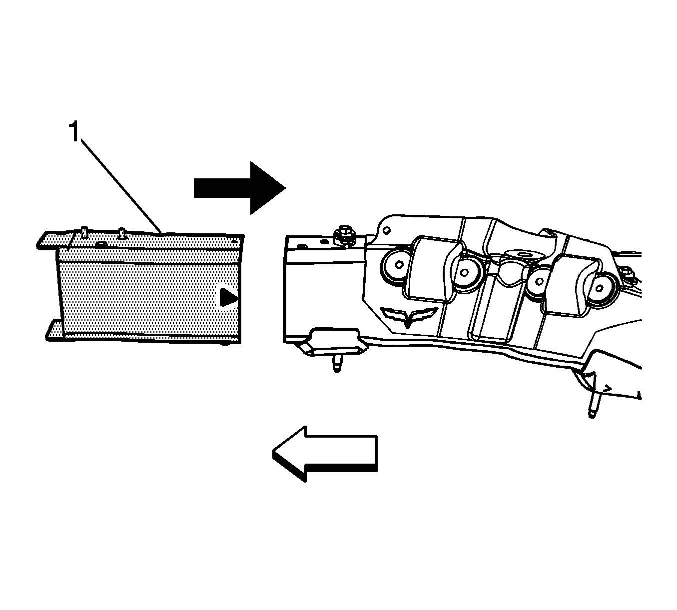
- Position the service frame section (1) to the existing frame.
- Maintain a gap of one and one half frame rail metal thickness at the sectioning joint (1) and clamp in place.
- Inspect the frame measurements three-dimensional to ensure proper position of the service frame section.
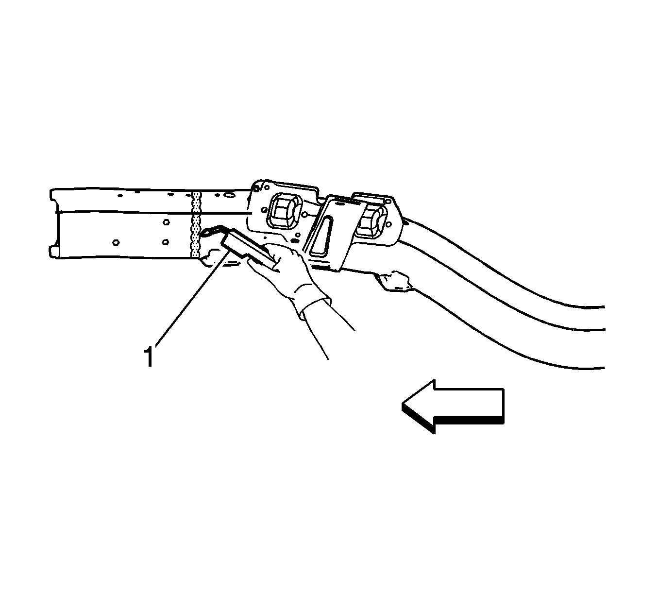
- Using a metal inert gas (MIG) welder, weld completely around the sleeve joint.
- Install the front impact bar. Refer to Front Bumper Impact Bar Replacement .
- Apply the sealers and anti-corrosion materials to the repair area. Refer to Anti-Corrosion Treatment and Repair .
- Paint the repair area. Refer to Basecoat/Clearcoat Paint Systems .
- Install all related panels and components.
- Connect the negative battery cable. Refer to Battery Negative Cable Disconnection and Connection .
- Enable the SIR system. Refer to SIR Disabling and Enabling .
Important: Use a 25-mm (1-in) stitch weld to avoid minimal heat distortion.
Important: DO NOT top coat any bonding surface. Use primer only on bonding surfaces. Refer to adhesive manufacturer's recommendations.
Front Rail End Replacement Z06
Tools Required
J 42058 Frame Adapter Clamp
Removal Procedure
The service assemblies for the left and the right front end frame rails are pre-sleeved, 6063-T7 aluminum, hydro-formed parts, which correlate directly with the die mark located on the front frame rails.
Caution: Refer to Approved Equipment for Collision Repair Caution in the Preface section.
- Disable the SIR system. Refer to SIR Disabling and Enabling .
- Disconnect the negative battery cable. Refer to Battery Negative Cable Disconnection and Connection .
- Remove all related panels and components.
- Remove the front impact bar. Refer to Front Bumper Impact Bar Replacement .
- Note the location and remove the sealers and anti-corrosion materials from the repair area. Refer to Anti-Corrosion Treatment and Repair .
- Repair as much of the damage as possible to the factory specifications.
- Use J 42058 to secure the vehicle if pulling and straightening are required.
- Locate the die-mark (1) on the damaged frame rail.
- At the die mark align a sliding square or similar tool square to surface to the vertical walls of the frame rail.
- Scribe a line to both sides of the frame rail.
- Apply masking tape (1) to the scribe line completely around the frame rail.
- Cut the frame rail at the rear edge of the tape line using a reciprocating saw or equivalent tool (1).
- Remove the damaged frame rail end section (1).
Caution: Refer to Collision Sectioning Caution in the Preface section.
Important: Hand tools, saw blades and abrasives used for aluminum repairs should be dedicated for aluminum only to prevent contamination.
Installation Procedure
- Grind the existing frame rail sectioning location to a 60 degree angle.
- Clean and prepare all of the welded mating surfaces.
- Position the service frame section (1) to the existing frame.
- Maintain a gap of one frame rail metal thickness at the sectioning joint (1) and clamp in place.
- Inspect the frame measurements three-dimensional to ensure proper position of the service frame section.
- Using a PULSED-MIG welder, weld 50 mm (2 in) stitch welds to the top and bottom of the sleeve joint.
- Using a PULSED-MIG welder, weld 50 mm (2 in) stitch welds to the inner and outer vertical walls of the sleeve joint.
- Inspect the frame measurements three-dimensional to ensure proper position of the service frame section.
- Using a PULSED-MIG welder, complete the welding of the sleeve joint using the 2 minute cooling down period for every 2 minutes or 100 mm (4 in) of welding.
- Install the front impact bar. Refer to Front Bumper Impact Bar Replacement .
- Apply the sealers and anti-corrosion materials to the repair area. Refer to Anti-Corrosion Treatment and Repair .
- Paint the repair area. Refer to Basecoat/Clearcoat Paint Systems .
- Install all related panels and components.
- Connect the negative battery cable. Refer to Battery Negative Cable Disconnection and Connection .
- Enable the SIR system. Refer to SIR Disabling and Enabling .

Important: Use a stainless steel brush to remove the oxide layer prior to welding.
Important:
• Recommend 2 weld passes (root and cap). • Recommend wire alloy is 5356 and wire size is 0.035. The shielding gas is 100 percent Argon. • A 2 minute cooling down period is recommend for every 2 minutes or 100 mm (4 in) of welding.
Important: DO NOT top coat any bonding surface. Use primer only on bonding surfaces. Refer to adhesive manufacturer's recommendations.
