For 1990-2009 cars only
Tools Required
J 42640 Steering Column Anti Rotation Pin
Removal Procedure
- Disable the SIR system. Refer to SIR Disabling and Enabling.
- Insert J 42640 into the bottom of the lower trim cover.
- Remove the Closeout Insulator Panel. Refer to Instrument Panel Insulator Panel Replacement.
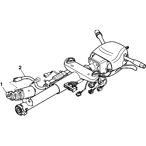
- Disconnect the cable assembly (2) from the telescope drive motor assembly (1).
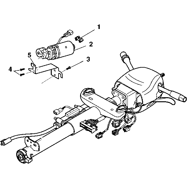
- Remove the connector clip (1) from the telescope drive motor assembly connector (2).
- Remove the 2 pan head tapping screws (4) from the telescope drive bracket (5).
- Remove the telescope drive motor assembly (2) from the telescope drive bracket (5).
- Remove the pan head tapping screw (3) from the telescope drive bracket (5).
- Remove the telescope drive bracket (5) from the jacket assembly.
Caution: Refer to SIR Caution in the Preface section.


Installation Procedure
- Install the telescope drive bracket (5) to the jacket assembly.
- Install the pan head tapping screw (3) to the telescope drive bracket (5).
- Install the guide retainer bolts.
- Install the telescope drive motor assembly (2) to the telescope drive bracket (5).
- Install the 2 pan head tapping screws (4) to the telescope drive bracket (5).
- Install the connector clip (1) to the telescope drive motor assembly connector (2).
- Connect the cable assembly (2) to the telescope drive motor assembly connector (1).
- Install the Closeout Insulator Panel. Refer to Instrument Panel Insulator Panel Replacement.
- Enable the SIR system. Refer to SIR Disabling and Enabling.
- Remove J 42640 from the bottom of the lower trim cover.

Notice: Refer to Fastener Notice in the Preface section.
Tighten
Tighten the screw to 7 N·m (62 lb in).
Tighten
Tighten the screws to 7 N·m (62 lb in).

Caution: Improper routing of the wire harness assembly may damage the inflatable restraint steering wheel module coil. This may result in a malfunction of the coil, which may cause personal injury.
