Removal Procedure
- Remove the valve rocker arm covers. Refer to Valve Rocker Arm Cover Replacement - Left Side or Valve Rocker Arm Cover Replacement - Right Side.
- Remove the valve rocker arm bolts.
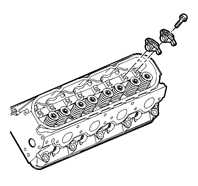
- Remove the valve rocker arms.
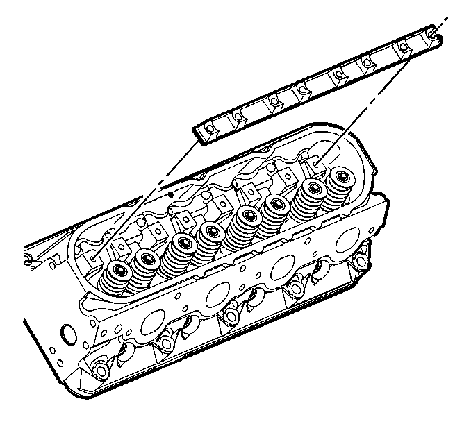
- Remove the valve rocker arm pivot support.
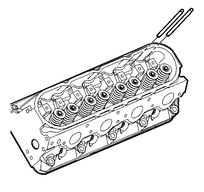
- Remove the pushrods.
- Clean and inspect the valve rocker arms and pushrods. Refer to Valve Rocker Arm and Push Rod Cleaning and Inspection.

Important: Place the valve rocker arms, valve pushrods, and pivot support, in a rack so that they can be installed in the same location from which they were removed.


Installation Procedure
- Lubricate the valve rocker arms and pushrods with clean engine oil.
- Lubricate the flange of the valve rocker arm bolts with clean engine oil.
- Install the valve rocker arm pivot support.
- Install the pushrods.
- Install the rocker arms and bolts.
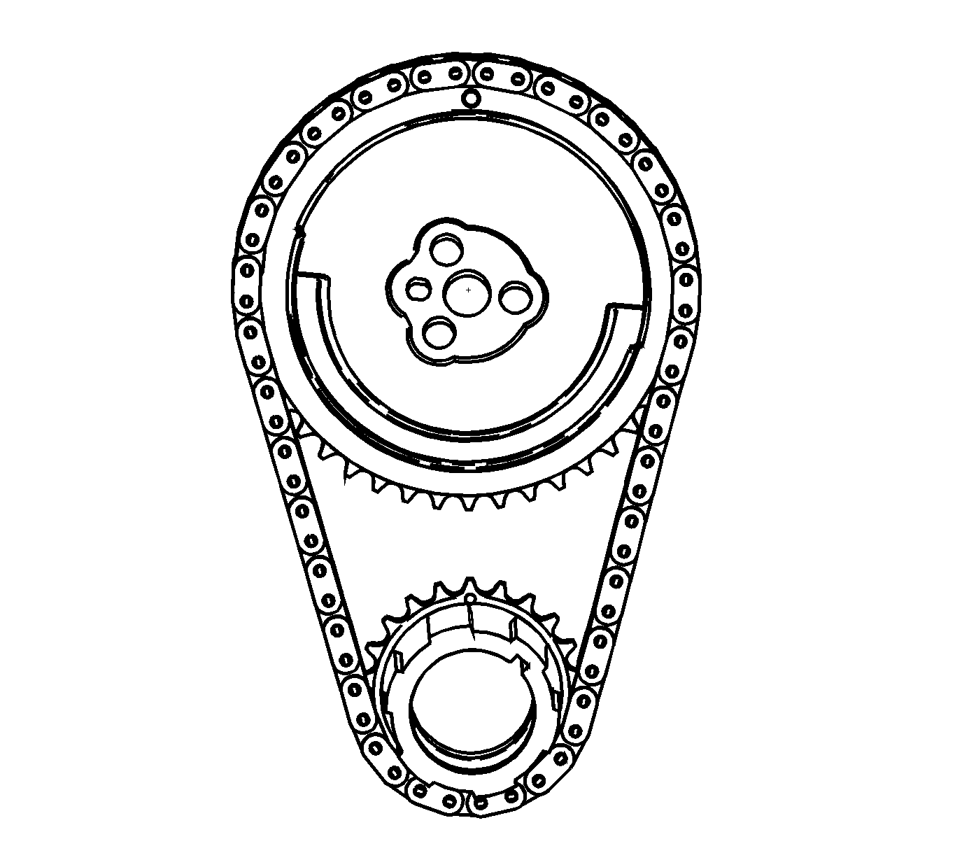
- Rotate the crankshaft until number one piston is at top dead center of compression stroke.
- With the engine in the number one firing position, tighten the following valve rocker arm bolts:
- Rotate the crankshaft 360 degrees.
- Tighten the following valve rocker arm bolts:
- Install the valve rocker arm covers. Refer to Valve Rocker Arm Cover Replacement - Left Side or Valve Rocker Arm Cover Replacement - Right Side.

Important:
• When using the valve train components again, always install the components to the original location and position. • Valve lash is net build, no valve adjustment is required.

Important: Ensure the pushrods seat properly to the valve lifter sockets.

Important:
• Ensure the pushrods seat properly to the ends of the rocker arms. • DO NOT tighten the rocker arm bolts at this time.

In this position, cylinder number one rocker arms will be off lobe lift, and the crankshaft sprocket key will be at the 1:30 position. The camshaft and crankshaft sprocket alignment marks will be in the 12 o'clock positions. If viewing from the rear of the engine, the additional crankshaft pilot hole, non-threaded, will be in the 10:30 position.
The engine firing order is 1, 8, 7, 2, 6, 5, 4, 3.
Cylinders 1, 3, 5 and 7 are left bank.
Cylinders 2, 4, 6, and 8 are right bank.
Notice: Refer to Fastener Notice in the Preface section.
Tighten
| • | Tighten exhaust valve rocker arm bolts 1, 2, 7, and 8 to 30 N·m (22 lb ft). |
| • | Tighten intake valve rocker arm bolts 1, 3, 4, and 5 to 30 N·m (22 lb ft). |
Tighten
| • | Tighten exhaust valve rocker arm bolts 3, 4, 5, and 6 to 30 N·m (22 lb ft). |
| • | Tighten intake valve rocker arm bolts 2, 6, 7, and 8 to 30 N·m (22 lb ft). |
