GM Service Manual Online
For 1990-2009 cars only

Lubrication Description 6.2L LS3
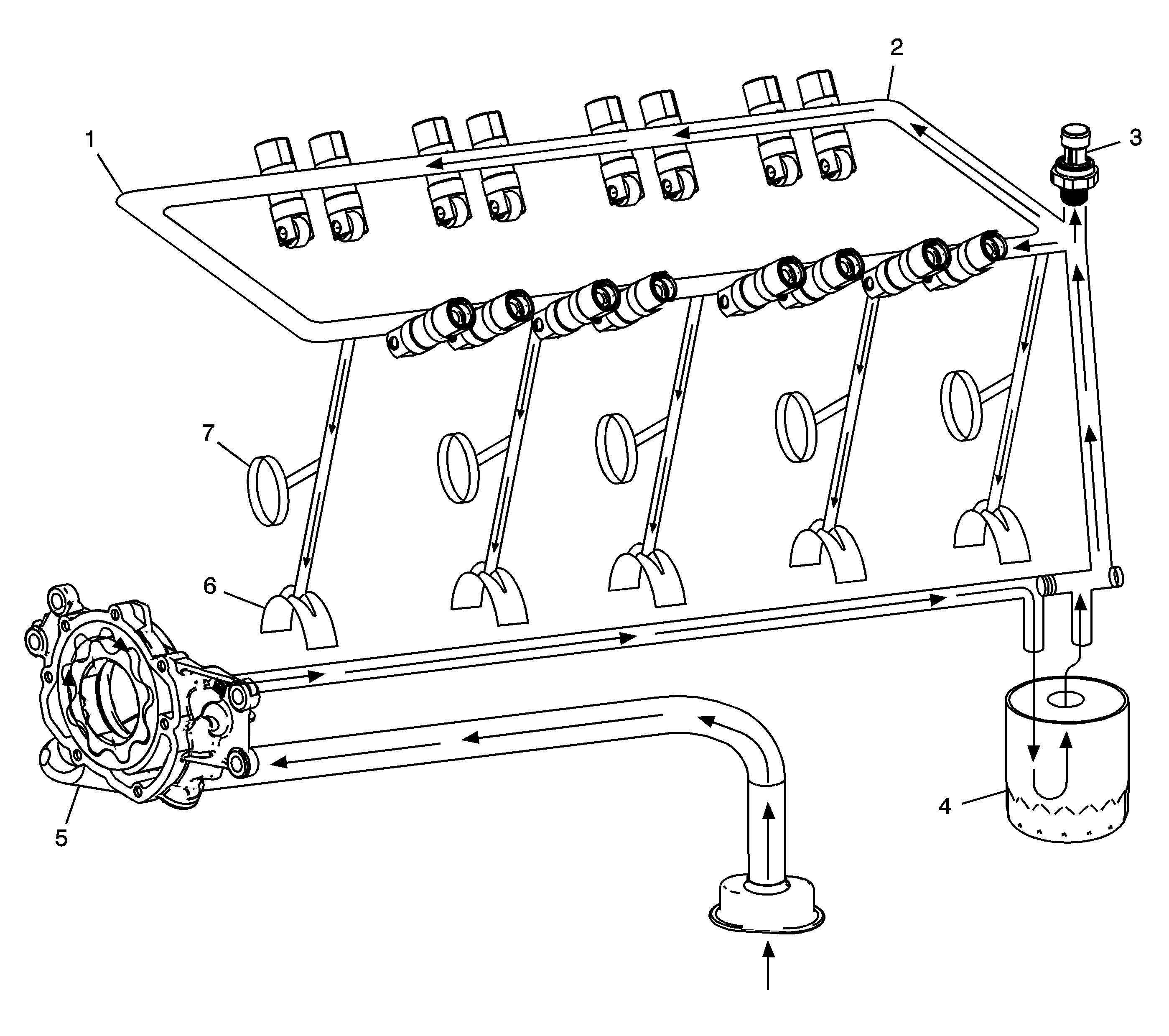

Object Number: 1408881  Size: LF

Engine lubrication is supplied by a gerotor type oil pump assembly (5). The pump is mounted on the front of the engine block and driven directly by the crankshaft sprocket. The pump gears rotate and draw oil from the oil pan sump through a pick-up screen and pipe. The oil is pressurized as it passes through the pump and is sent through the engine block lower oil gallery. Contained within the oil pump assembly is a pressure relief valve that maintains oil pressure within a specified range.

Pressurized oil is directed through the engine block lower oil gallery to the full flow oil filter (4) where harmful contaminants are removed. A bypass valve is incorporated into the oil filter, which permits oil flow in the event the filter becomes restricted.

Oil is then directed from the filter to the upper main oil galleries (1). Oil from the left upper oil gallery is directed to the crankshaft bearings (6) and camshaft bearings (7). Oil that has entered both the upper main oil galleries also pressurizes the valve lifter assemblies (2) and is then pumped through the pushrods to lubricate the valve rocker arms and valve stems. Oil returning to the pan is directed by the crankshaft oil deflector. The oil pressure sensor (3) is located at the top rear of the engine.

Lubrication Description 7.0L

Engine Lubrication Flow
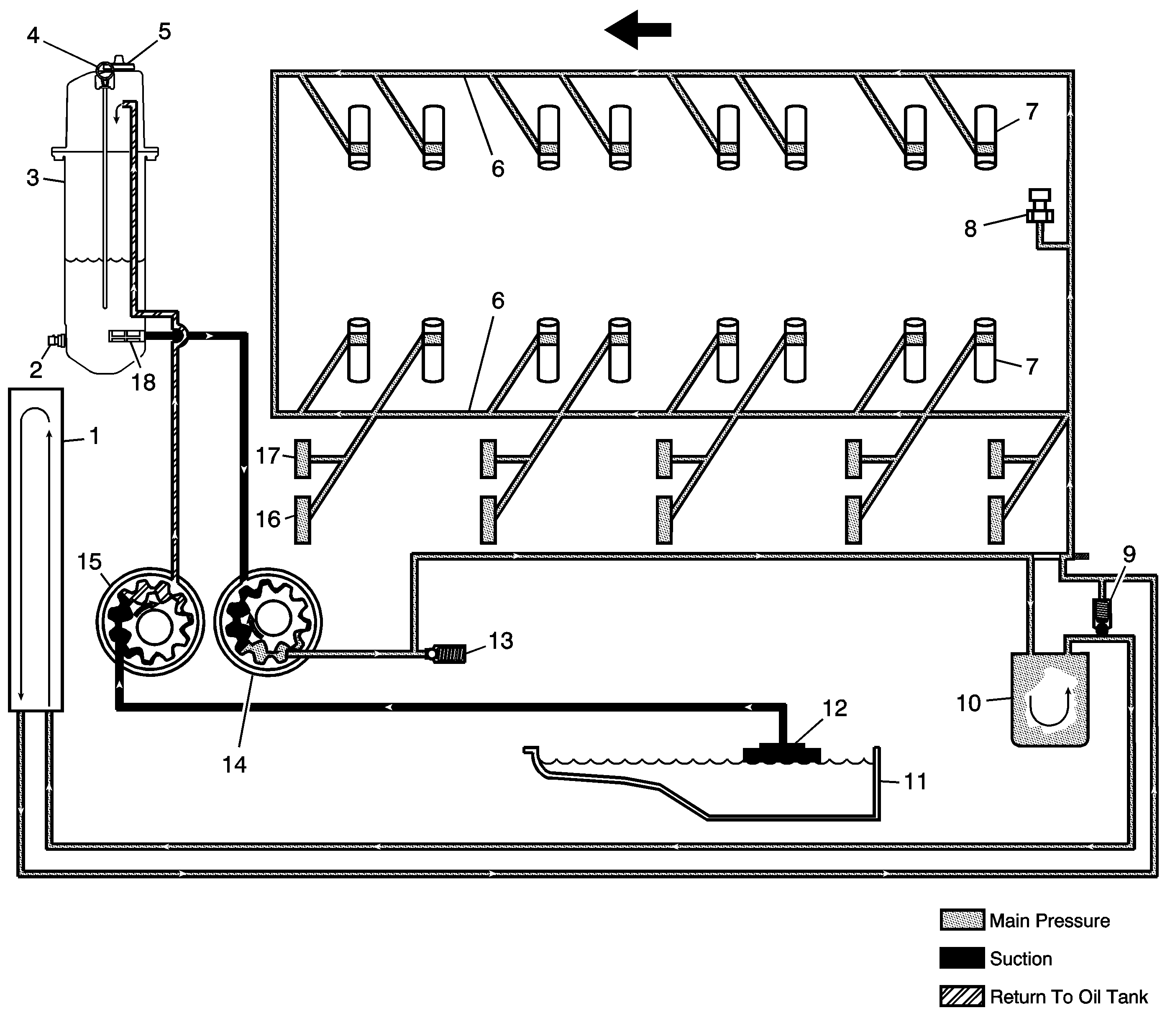

Object Number: 1552520  Size: LF
(1)Engine Oil Cooler
(2)Oil Temperature Sensor
(3)Engine Oil Tank
(4)Oil Level Indicator
(5)Oil Fill Cap
(6)Upper Main Oil Galleries
(7)Valve Lifters
(7)Valve Lifters
(8)Oil Pressure Sensor
(9)Bypass Valve - Oil Cooler
(10)Oil Filter
(11)Oil Pan Sump
(12)Oil Pump Screen
(13)Pressure Relief Valve - Oil Pump
(14)Oil Pump - Primary
(15)Oil Pump - Secondary
(16)Crankshaft Bearings
(17)Camshaft Bearings
(18)Oil Pump Screen - Oil Tank

Engine lubrication is supplied by a gerotor type oil pump assembly. The oil pump assembly consists of 2 pump housings, 2 separate gear sets, and 1 pressure relief valve. Refer to Oil Pump Assembly in Disassembled Views . The front or forward gear set is the secondary pump (15). The rear or rearward gear set is the primary pump (14). The pump assembly is mounted at the front of the engine and driven directly by the crankshaft sprocket. The primary pump (14) gears rotate and draw oil from the engine oil tank (3) through the oil pump screen (18). The oil is pressurized as it passes through the primary pump and is sent through the engine block lower oil gallery. Contained within the primary pump is a pressure relief valve (13) that maintains oil pressure within a specified range. Pressurized oil is directed through the engine block lower oil gallery to the full flow oil filter (10) where harmful contaminants are removed. A bypass valve is incorporated into the oil filter, which permits oil flow in the event the filter becomes restricted. Oil exits the oil filter and is then directed to the external oil cooler (1). A bypass valve (9) is incorporated into the oil cooler hose assembly in the event oil flow within the cooler is restricted. Oil returns from the oil cooler and is directed to the upper main oil galleries (6). Oil from the left upper oil gallery is directed to the crankshaft bearings (16) and camshaft bearings (17). Oil that has entered both the upper main oil galleries also pressurizes the valve lifter assemblies (7), and is then pumped through the pushrods to lubricate the valve rocker arms and valve stems. Oil returns to the oil pan (11), where the secondary pump (15) draws oil through a pump screen (12). The secondary pump (15) returns oil to the engine oil tank (3). Incorporated within the engine oil tank assembly are the oil level indicator (4), oil fill cap (5), oil temperature sensor (2), positive crankcase ventilation (PCV) fresh air port, and a serviceable oil pump screen (18). The engine oil pressure sensor (8) is located at the top rear of the engine assembly.