Driveline Assembly

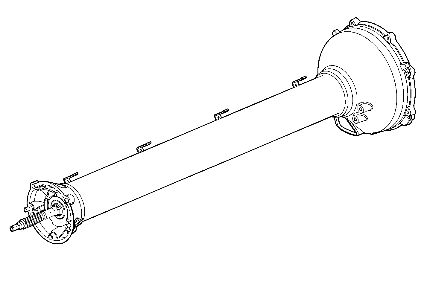
Automatic transmission application shown.
The driveline support assembly consists of a driveline support tube, with rear bell housing, and an internal propeller shaft assembly. The front of the driveline assembly mounts to the engine bellhousing. In manual transmission applications, the clutch actuator is retained to the front of the tube and the shifter linkage is mounted to brackets at the top center area. The driveline support assembly is specific for each vehicle as equipped, either automatic or manual transmission applications.
Propeller Shaft Assembly (Automatic Transmission)

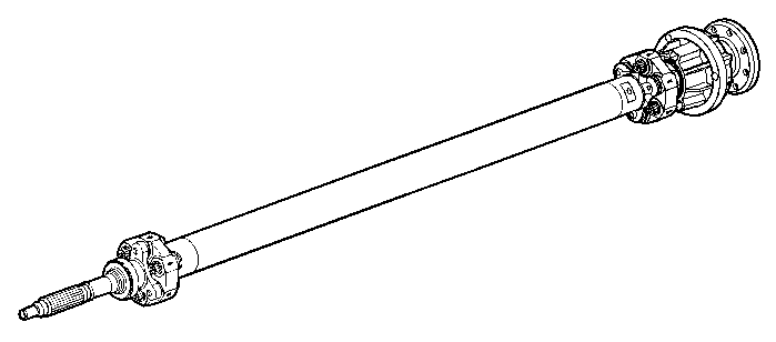
The automatic transmission propeller shaft assembly consists of a splined front input shaft, front coupling, propeller shaft, rear coupling, bolts, and a bearing and housing assembly. The input shaft, propeller shaft, couplings and bearing and housing assembly are balanced as an assembly. The front of the propeller shaft assembly is supported, at the input shaft, by a ball type bearing. An O-ring, located in the front of the driveline support tube, prevents the front bearing outer race from spinning. The rear of the propeller shaft assembly is supported by a bearing and housing assembly. The bearing and housing assembly consists of a housing, internally splined input hub, externally splined flex plate spindle, O-rings, snap rings, and two ball type bearings. The propeller shaft assembly is retained in the driveline tube by an internal snap ring. The torque converter flex plate is retained to the flex plate spindle by bolts and is mated to the torque converter.
Propeller Shaft Assembly (Manual Transmission)

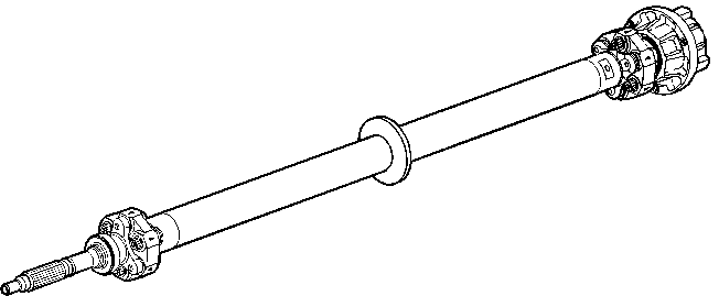
The manual transmission propeller shaft assembly consists of a splined front input shaft, front coupling, propeller shaft, rear coupling, bolts, and a bearing and housing assembly. The input shaft, propeller shaft, couplings and bearing and housing assembly are balanced as an assembly. The front of the propeller shaft assembly is supported, at the input shaft, by a ball type bearing. An O-ring, located in the front of the driveline support tube, prevents the front bearing outer race from spinning. The rear bearing of the propeller shaft assembly is supported by a bearing and housing assembly. The bearing and housing assembly consists of a housing, internally splined hub, pilot bushings, O-rings, snap rings, a wave washer, and two ball type bearings. The bearing housing hub internal splines couple to the manual transmission splined input shaft. The propeller shaft assembly is retained in the driveline tube by an internal snap ring. The propeller shaft tube has an overspeed limiter, snubber, that prevents permanent propeller shaft damage as a result of a downshift above recommended speeds.
Important: Disassembly and improper reassembly of the propeller shaft components may result in driveline vibration. The propeller shaft and components should be kept free of any foreign material which could upset balance and also produce driveline vibration.
When servicing the engine, transaxle, or driveline support assembly, the proper installation procedure must be followed. Automatic transmission applications have a specific installation procedure and sequence of installation steps. Failure to follow proper procedures may cause damage to other vehicle driveline components.