Tool Required
| • | J 42155
Getrag Axle Differential Housing Lifting Tool |
| • | J 42173
Getrag Axle Ring Gear Holder |
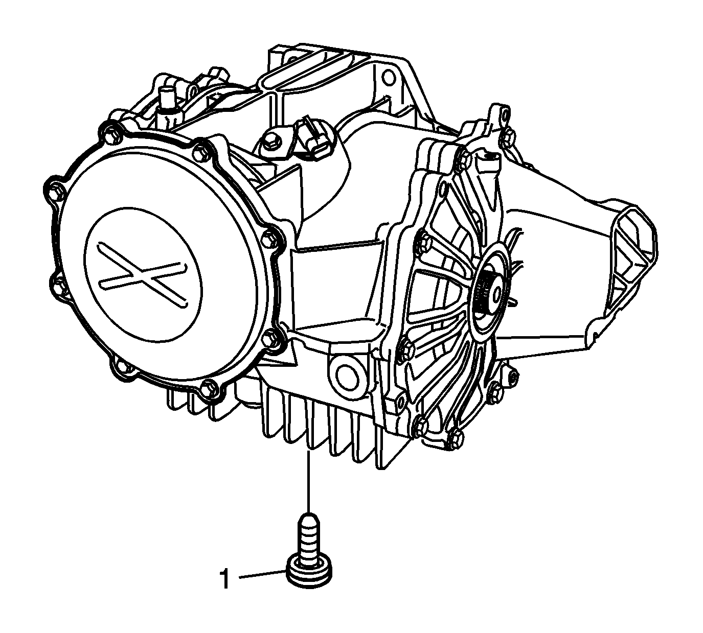
- Remove the drain plug and washer (1) and allow the fluid to drain.
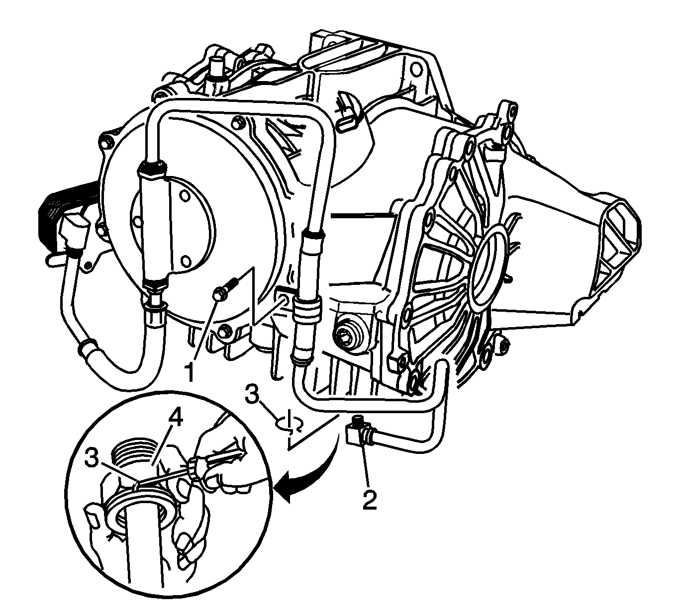
- To drain the fluid from models equipped
with a pump and cooler, perform the following steps:
| 2.1. | Remove the bolt (1) retaining the lower inlet pipe clamp. |
| 2.2. | Using a bent tip screwdriver, remove the quick connect fitting retaining ring (3) from the quick connect fitting (4), and discard the retaining ring. |
| 2.3. | Drain the fluid by pulling the lower inlet pipe (2) straight out of the quick connect fitting. |
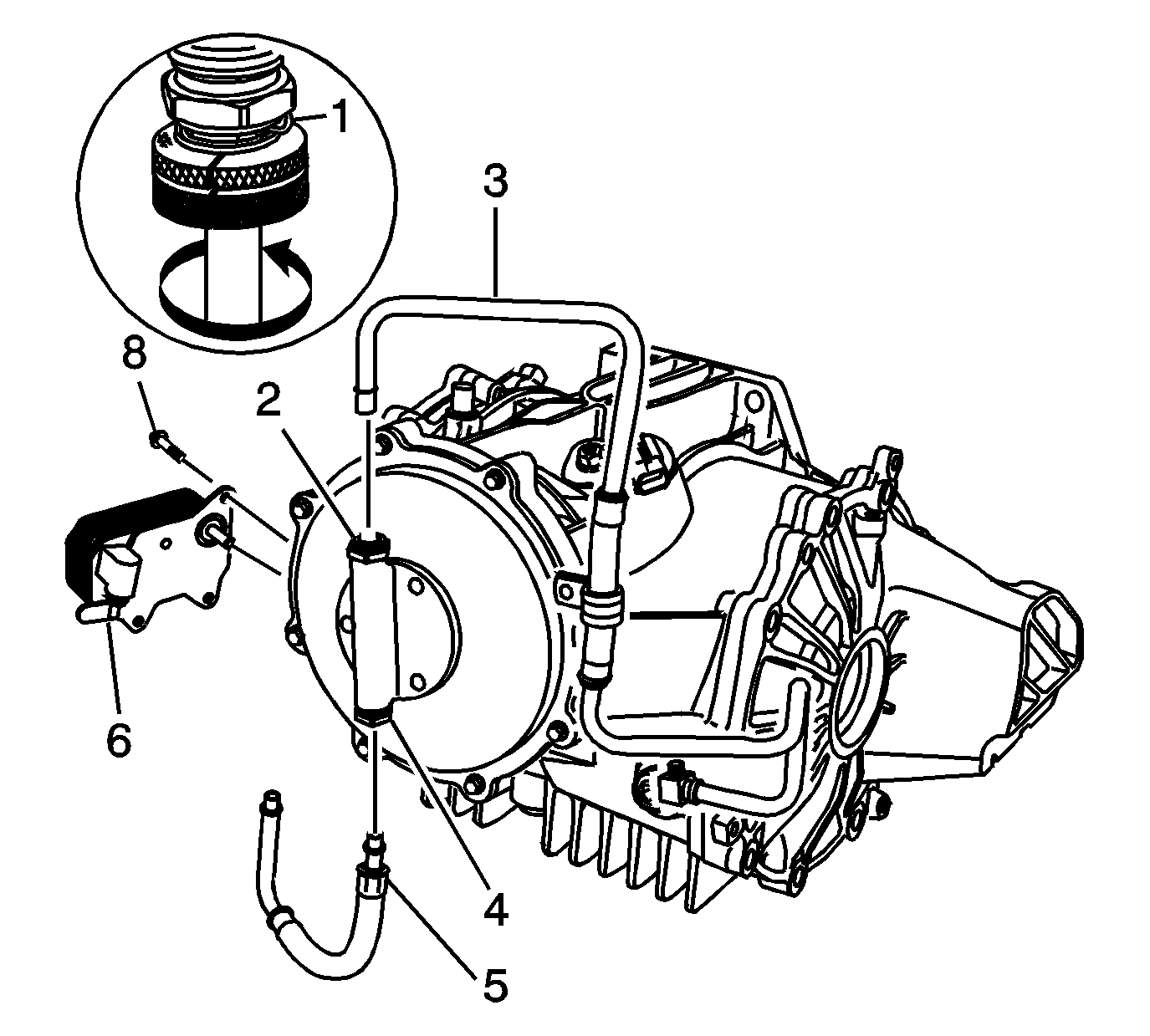
- For models equipped with a pump and cooler, perform the following steps to remove
the cooler and pipes:
| 3.1. | Using the
J 41623-B
, remove the inlet and outlet pipes by aligning notches on the
J 41623-B
with quick connect fittings (2, 4, 6)
and rotating the tool to release pipes (3 and 5) from the quick connect fittings. |
| 3.2. | Remove the 3 cooler retaining bolts (8). |
| 3.3. | Remove the cooler (7). |
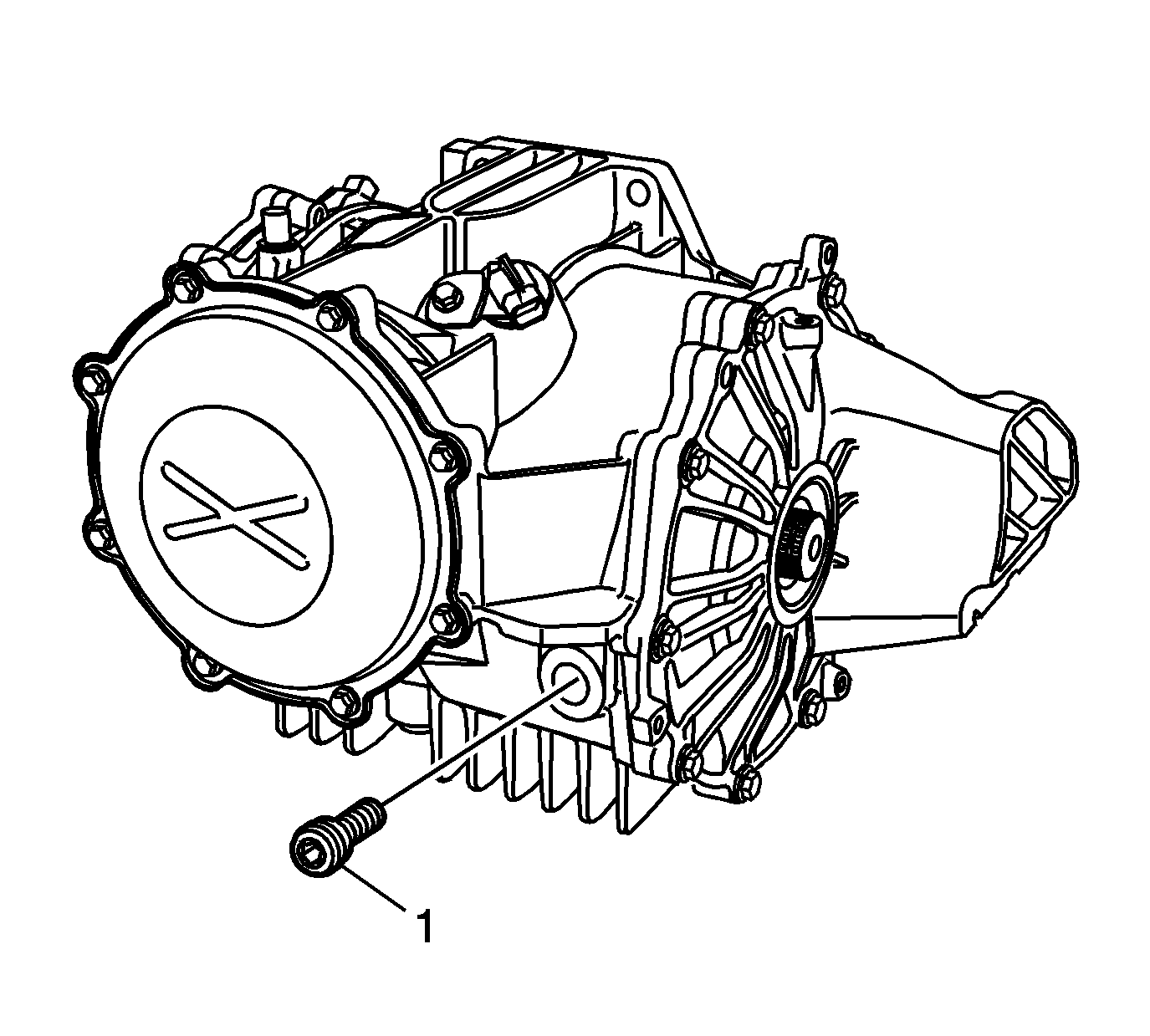
- Remove the fill plug and washer (1).
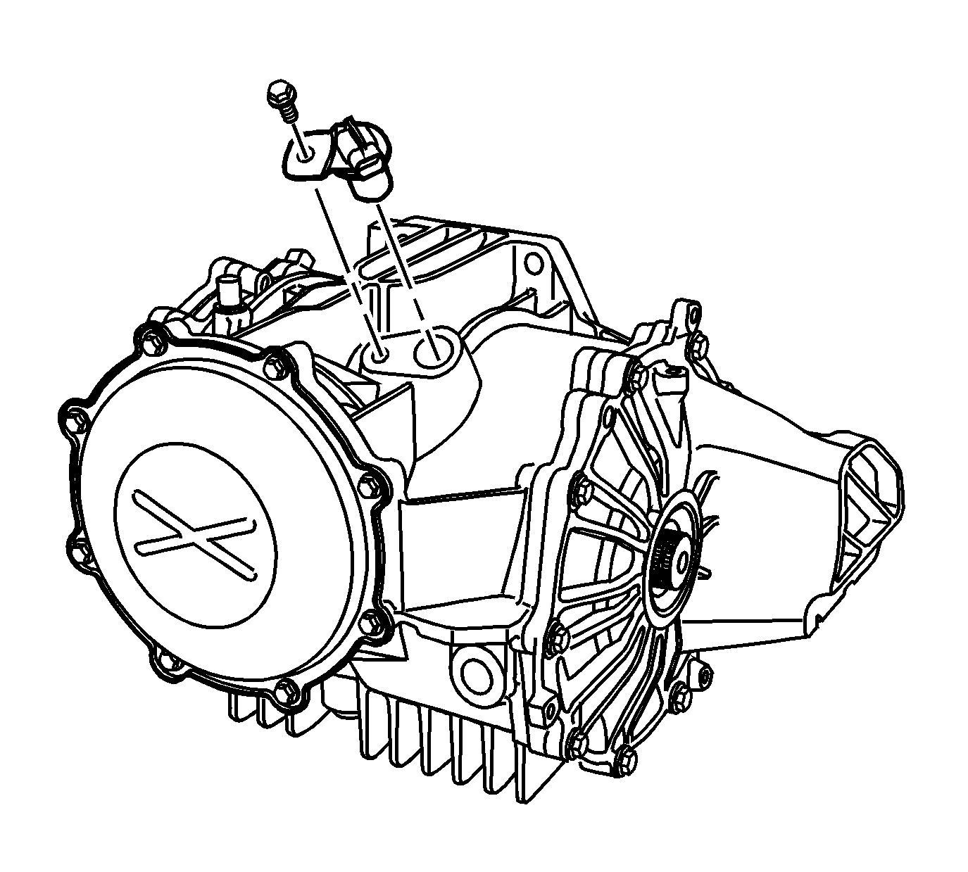
- Remove the vehicle speed sensor and bolt, if equipped.
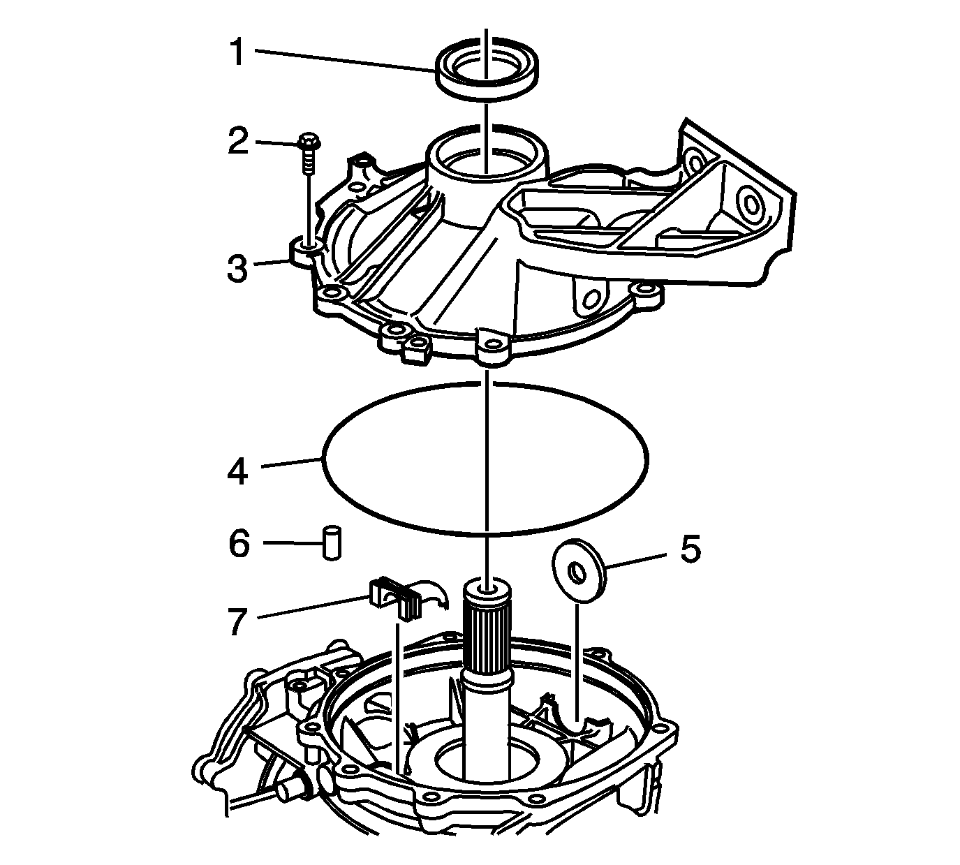
- Remove the left cover (3) and bolts (2).
- Remove the O-ring (4) and oil seal (1) from the cover.
- Remove the magnet (5) and dowel (6) from the carrier.
- Remove the oil trough (7).
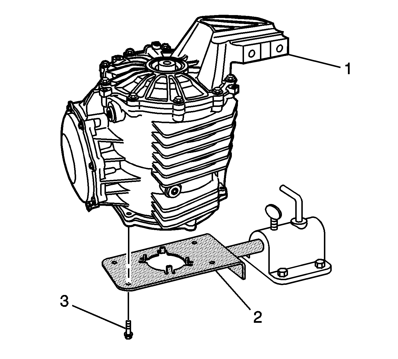
- Install the differential assembly (1) onto the
J 42173
(2).
Notice: Refer to Fastener Notice in the Preface section.
- Install 4 M8 x 1.25 bolts (3).
Tighten
Tighten the bolts to 30 N·m (22 lb ft).
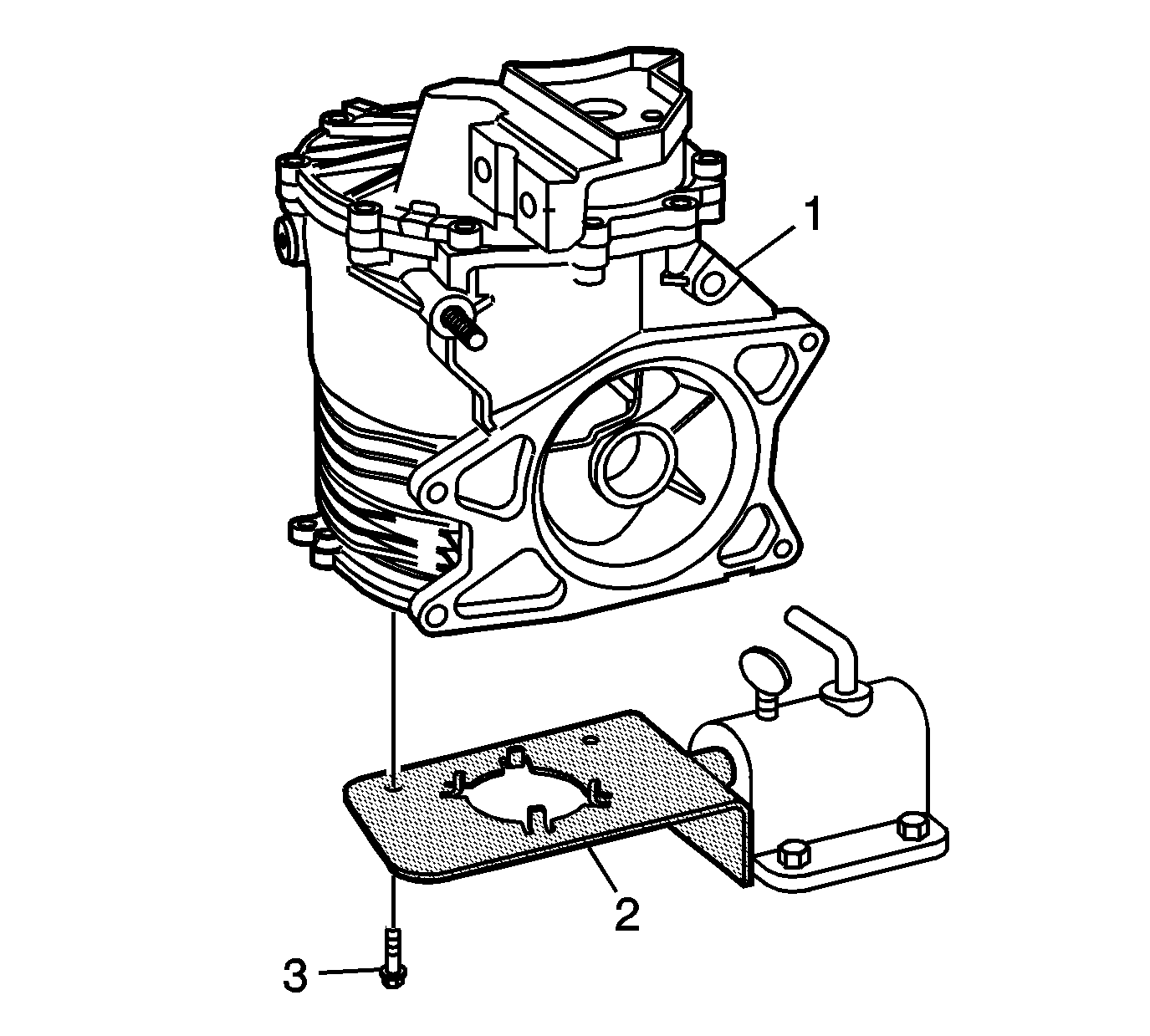
Important: Z06 models require the modification of
J 42173
, using
J-42173-10
.
- Install the differential assembly (1) onto the
J 42173
(2).
- Install 2 M8 x 1.25 bolts (3).
Tighten
Tighten the bolts to 30 N·m (22 lb ft).
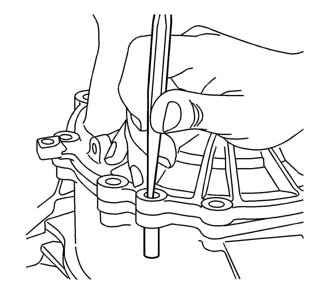
- Using a punch, remove the cover alignment pin.
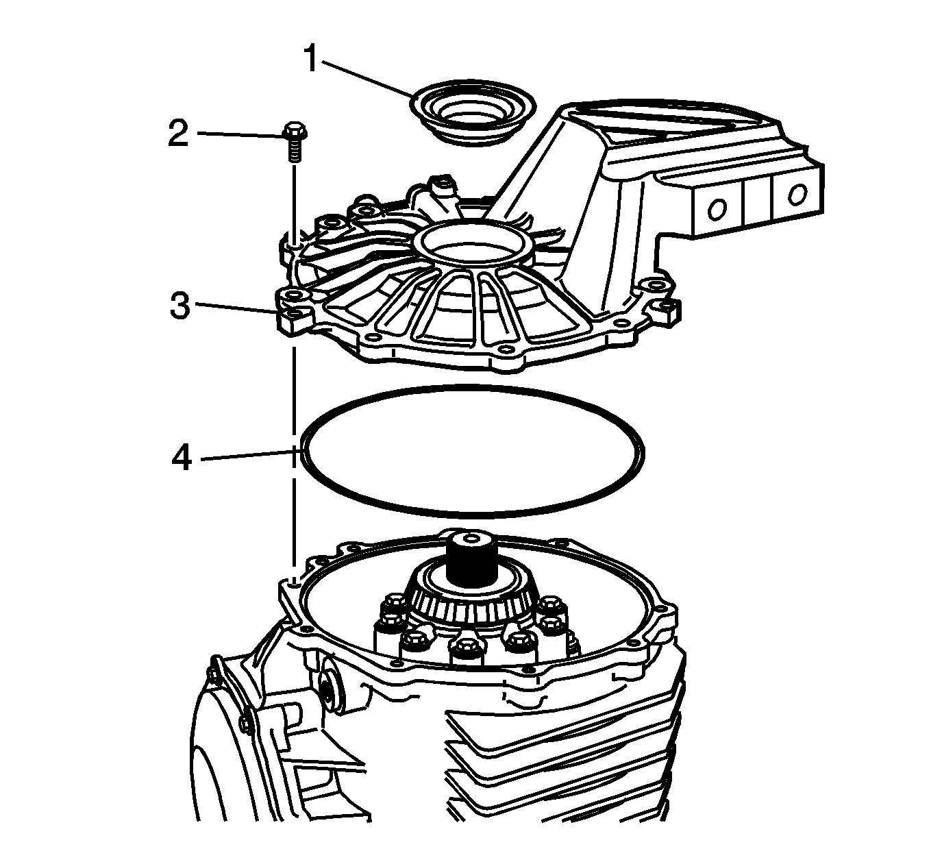
- Remove the right cover (3) and bolts (2) from the differential.
- Remove the O-ring (4) and oil seal (1) from the cover.
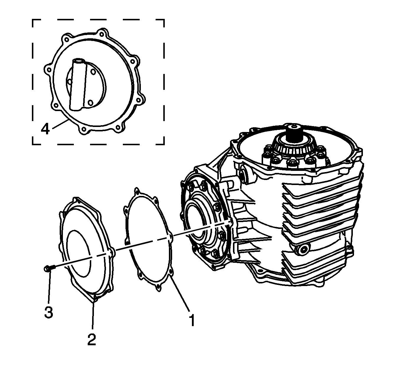
- Remove the rear cover (2), bolts (3), and gasket (1), or pump - some models (4).
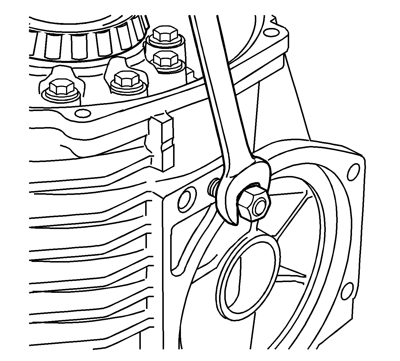
- Install 2 M10 x 1.5 nuts onto the transmission stud. Remove the stud from the
differential, if equipped.
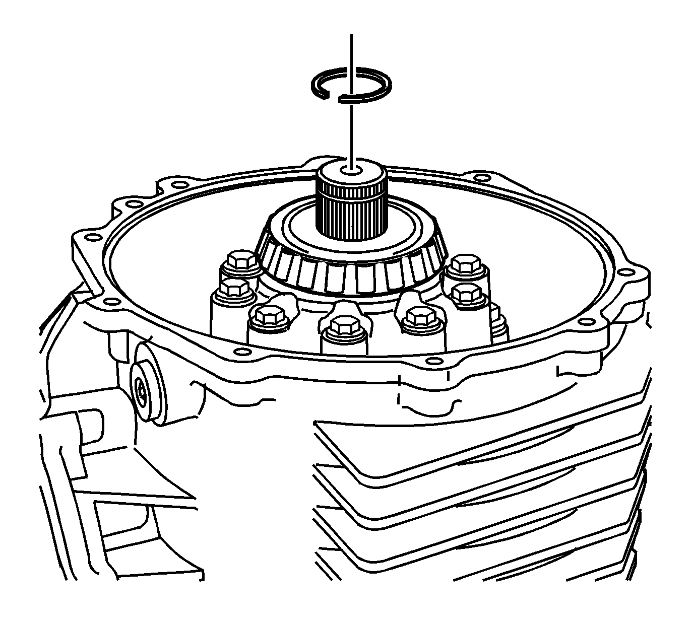
- Remove the C-clip from the output shaft.
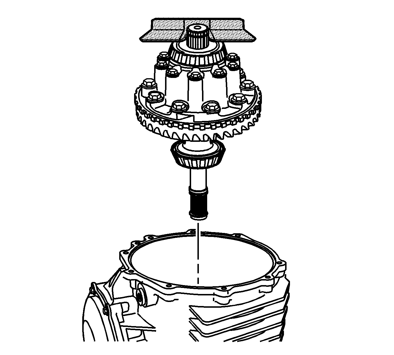
- Install the
J 42155
into the groove of the output shaft
in order to remove the differential case assembly.
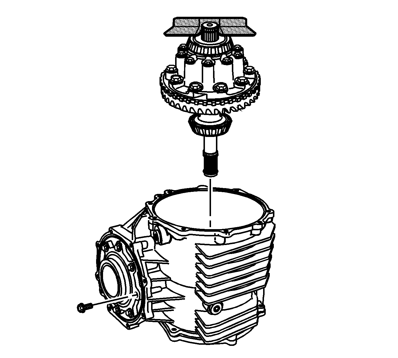
- Remove the pinion housing/cage bolts.
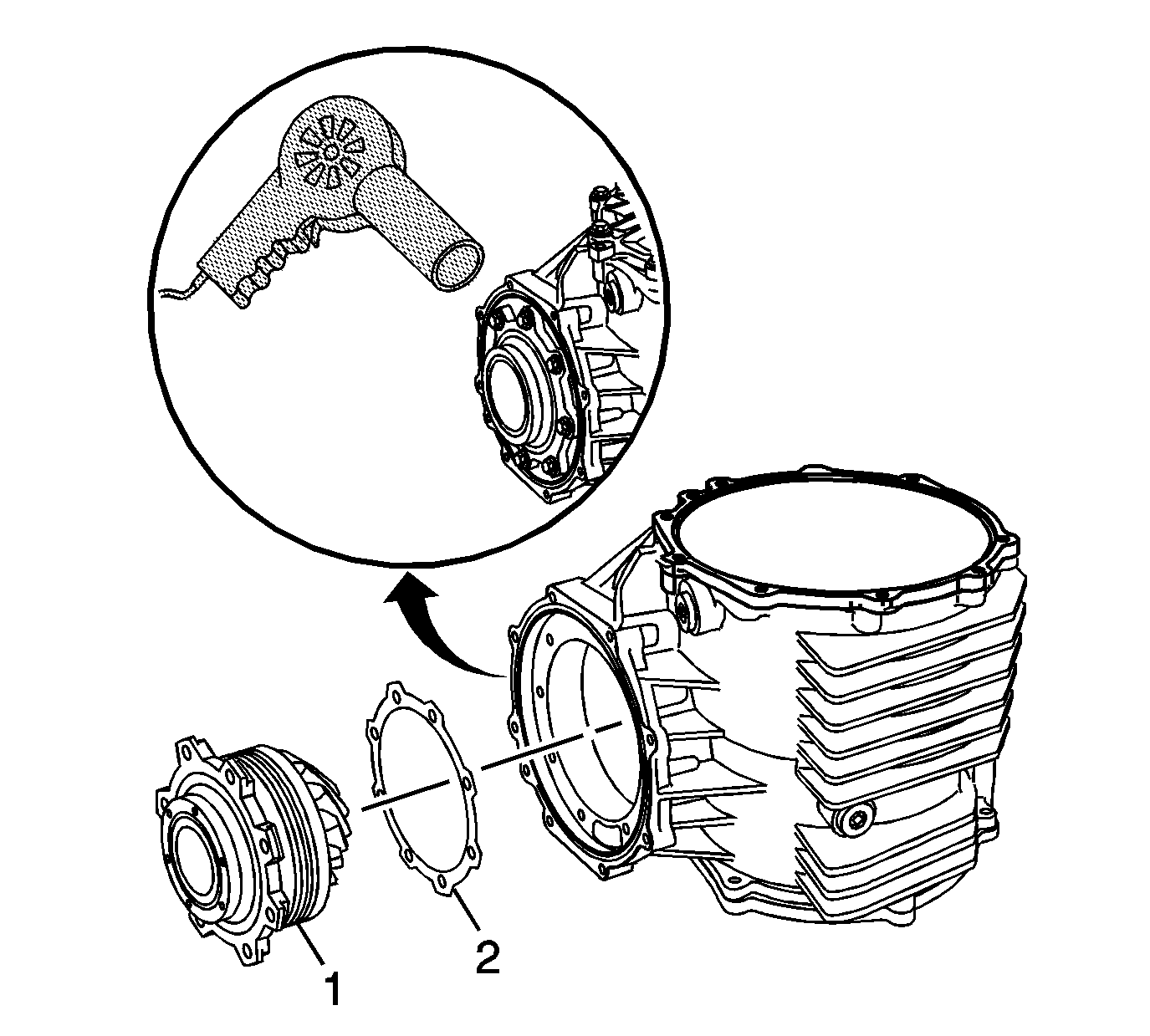
- Using the
J 25070
, heat the differential housing around
the pinion housing. Heating the housing will ease in pinion removal.
- Remove the pinion housing/cage assembly (1) and shims (2) from the differential housing. Mark or tag the shims for assembly.
Locate 2 screwdrivers or pry bars to the flange area of the pinion housing/cage to ease
in removal.
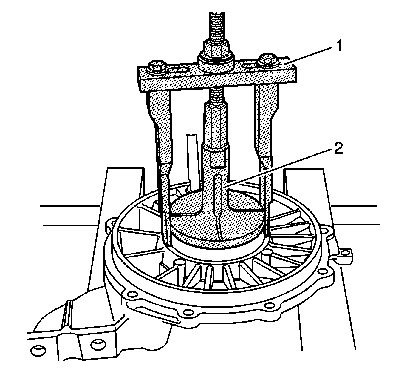
- Install the
DT-47596
(2) into the right cover.
Tighten securely into the bearing cup.
- Place
J 45124
(1) over
DT-47596
(2). Adjust legs for best fit. Install supplied bolt, nut, thrust bearing and washer. Hold
the bolt and tighten the nut to remove the bearing cup and shim.
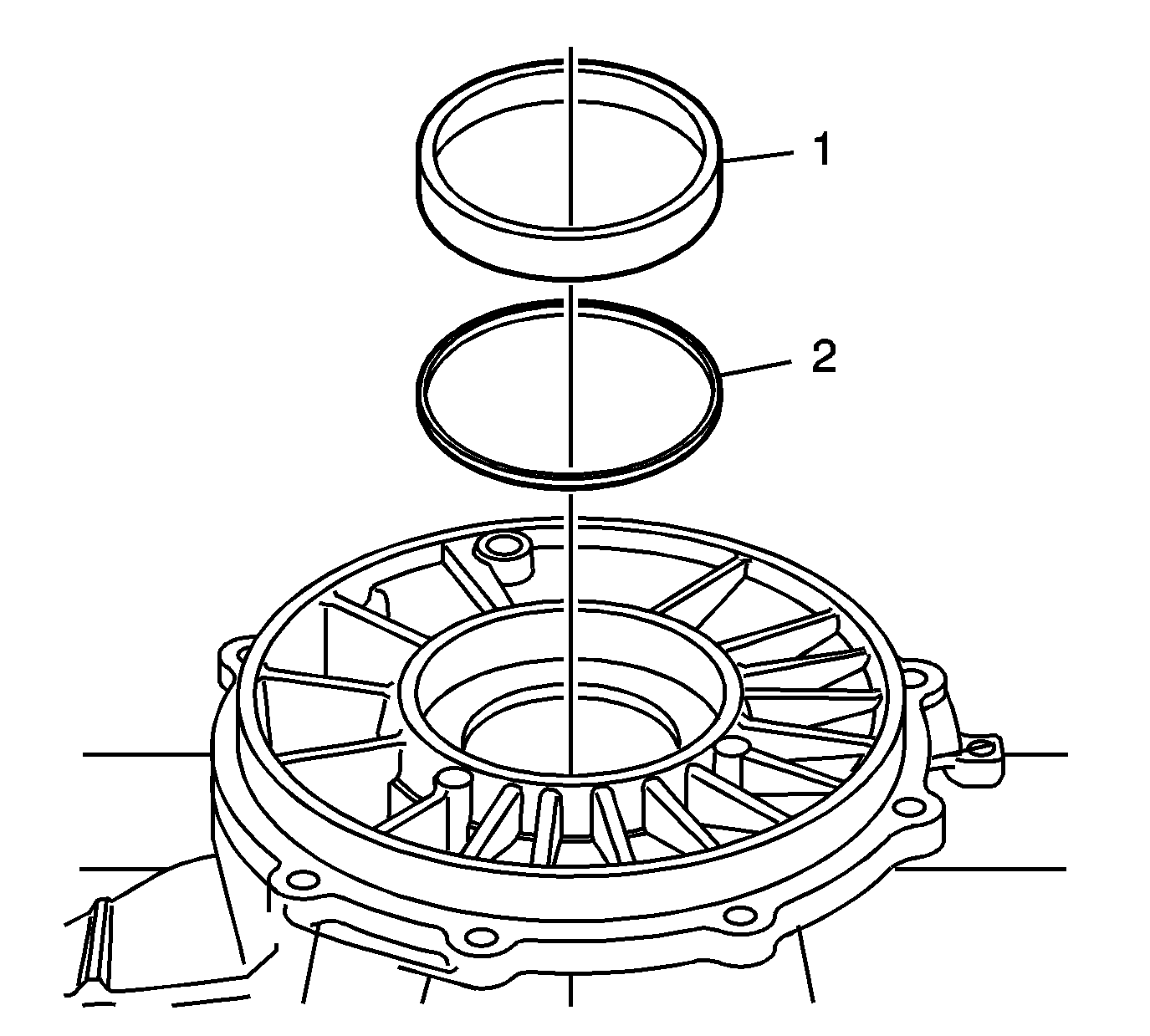
- Remove the bearing cup (1) and shim (2). Mark or tag the shims for
assembly.
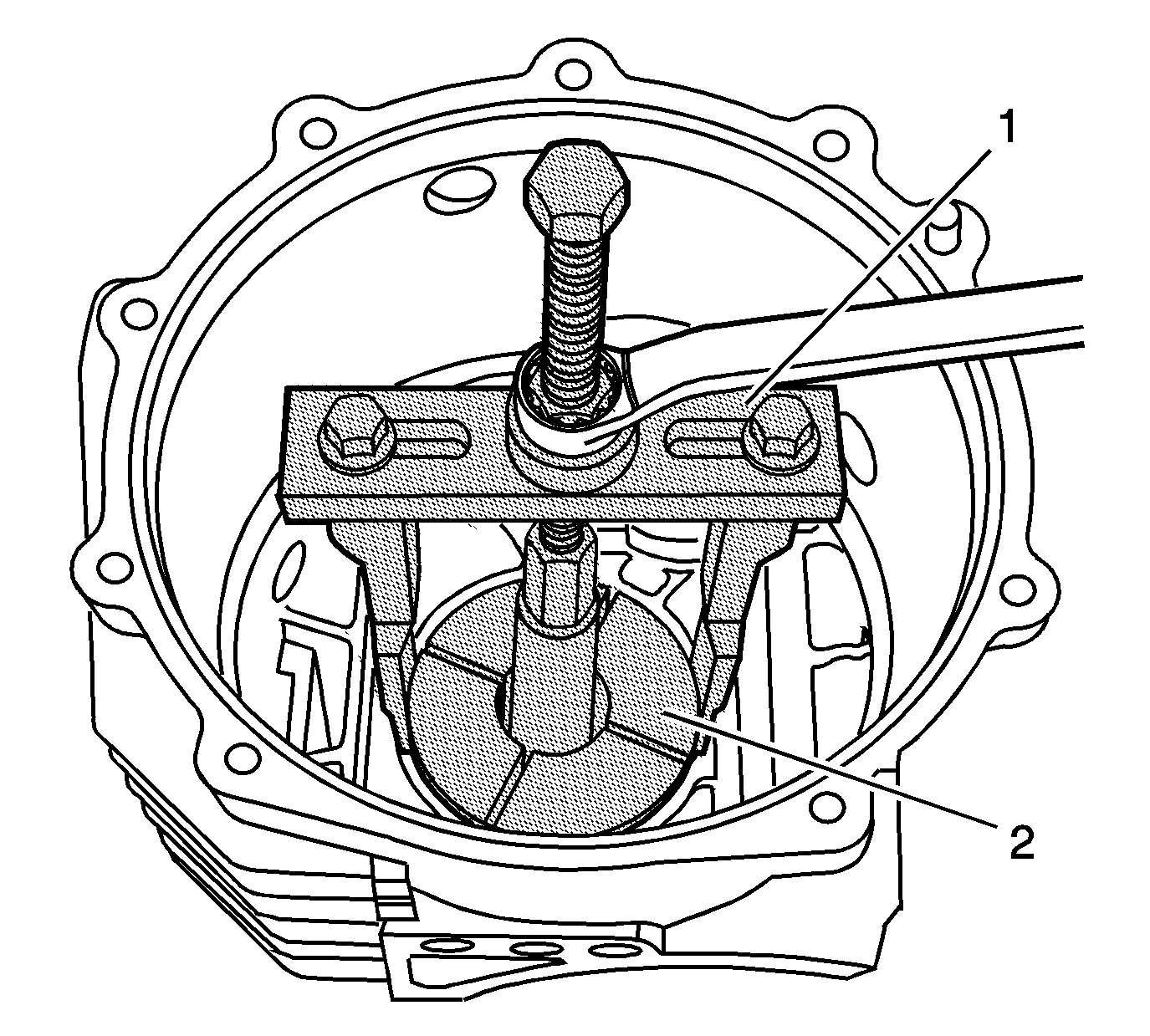
- Install the
DT-47596
(2)
into the differential housing, behind the left bearing cup. Tighten securely into the bearing cup.
- Place
J 45124
(1) over
DT-47596
(2). Adjust legs for best fit. Install supplied bolt, nut, thrust bearing and washer. Hold
the bolt and tighten the nut to remove the bearing cup and shim.
- Remove the cup (2) and shim (1) from the differential housing. Mark or tag the shims for assembly.


