Removal Procedure
Notice: Failure to follow the proper removal and installation procedures may result in damage to the engine crankshaft thrust bearing.
Notice: When tilting down the rear of the driveline, observe the clearance between the rear of the engine and the composite dash panel. Do not allow the engine to rest unsupported against the composite dash panel, or vehicle damage may result.
Notice: When lowering and removing the rear of the driveline, observe the clearance between the rear of the transaxle assembly and the underbody to prevent damage.
Important:
• For manual transmission applications, note the position and direction of the engine flywheel before removal. The flywheel does not use a locating pin for alignment. Mark or scribe the end of the crankshaft and the flywheel before component removal.
The engine flywheel must be reinstalled to the original position and direction. The engine flywheel will not initially seat against the crankshaft flange, but will be pulled onto the crankshaft by the engine flywheel bolts. This procedure requires a 3 stage
tightening process. • DO NOT remove the prop shaft hub or flex plate from the automatic transmission engine flywheel. The flywheel, prop shaft hub, and flex plate are balanced as an assembly. If service is required, the entire flywheel assembly should be replaced.
- Remove the catalytic converters. Refer to Catalytic Converter Replacement - Left Side and Catalytic Converter Replacement - Right Side.
- Remove the driveline support, if equipped with a automatic transmission. Refer to Driveline Support Assembly Replacement.
- Remove the clutch assembly, if equipped with a manual transmission. Refer to Clutch Assembly Replacement.
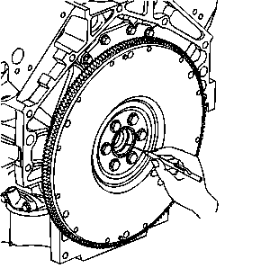
- Mark or scribe the end of the crankshaft and the manual transmission flywheel. Refer to Engine Balancing .
- If equipped with an automatic transmission, remove the engine flywheel bolts.
- If equipped with a manual transmission, remove the engine flywheel bolts.
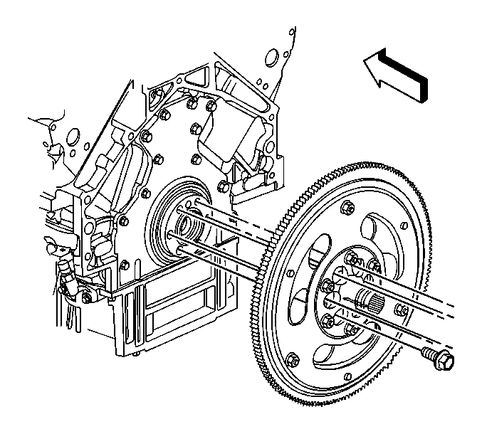
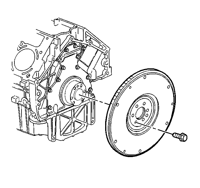
- Remove the engine flywheel.
Installation Procedure
Important: For manual transmission applications, note the position and direction of the engine flywheel before removal. The flywheel does not use a locating pin for alignment. Mark or scribe the end of the crankshaft and the flywheel before component removal. The engine flywheel must be reinstalled to the original position and direction. The engine flywheel will not initially seat against the crankshaft flange, but will be pulled onto the crankshaft by the engine flywheel bolts. This procedure requires a 3 stage tightening process.
DO NOT remove the prop shaft hub or flex plate from the automatic transmission engine flywheel. The flywheel, prop shaft hub, and flex plate are balanced as an assembly. If service is required, the entire flywheel assembly should be replaced.- If equipped with a manual transmission, align the mark or scribe on the crankshaft with the mark or scribe on the existing flywheel. Refer to Engine Balancing .
- Install the engine flywheel.
- Apply threadlock to the threads of the flywheel bolts. Refer to Adhesives, Fluids, Lubricants, and Sealers for the correct part number.
- Install the engine flywheel bolts until snug.
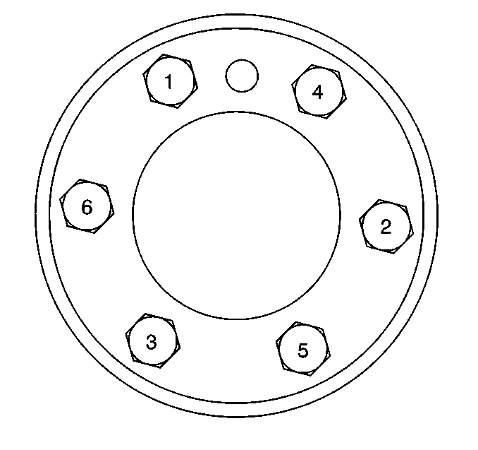
- Tighten the engine flywheel bolts a first pass in sequence to 20 N·m (15 lb ft).
- Tighten the engine flywheel bolts a second pass in sequence to 50 N·m (37 lb ft).
- Tighten the engine flywheel bolts a final pass in sequence to 100 N·m (74 lb ft).
- Install the driveline support, if equipped with a automatic transmission. Refer to Driveline Support Assembly Replacement.
- Install the clutch assembly, if equipped with a manual transmission. Refer to Clutch Assembly Replacement.
- Install the catalytic converter. Refer to Catalytic Converter Replacement - Left Side and Catalytic Converter Replacement - Right Side.
Notice: Refer to Fastener Notice in the Preface section.
Tighten
