Hood Plate Stud Replacement Corvette
Removal Procedure
The hood anchor plate assembly is riveted to the inside of the front frame rail. Access to the hood plate assembly would require the removal of the welded front bumper bar. A procedure was developed for the replacement of a broken hood stud without removing the front bar.
- Disable the SIR system. Refer to SIR Disabling and Enabling .
- Disconnect the negative battery cable. Refer to Battery Negative Cable Disconnection and Connection .
- Remove all related panels and components.
- Note the location and remove the sealers and anti-corrosion materials from the repair area, as necessary. Refer to Anti-Corrosion Treatment and Repair .
- Remove the hood hinge.
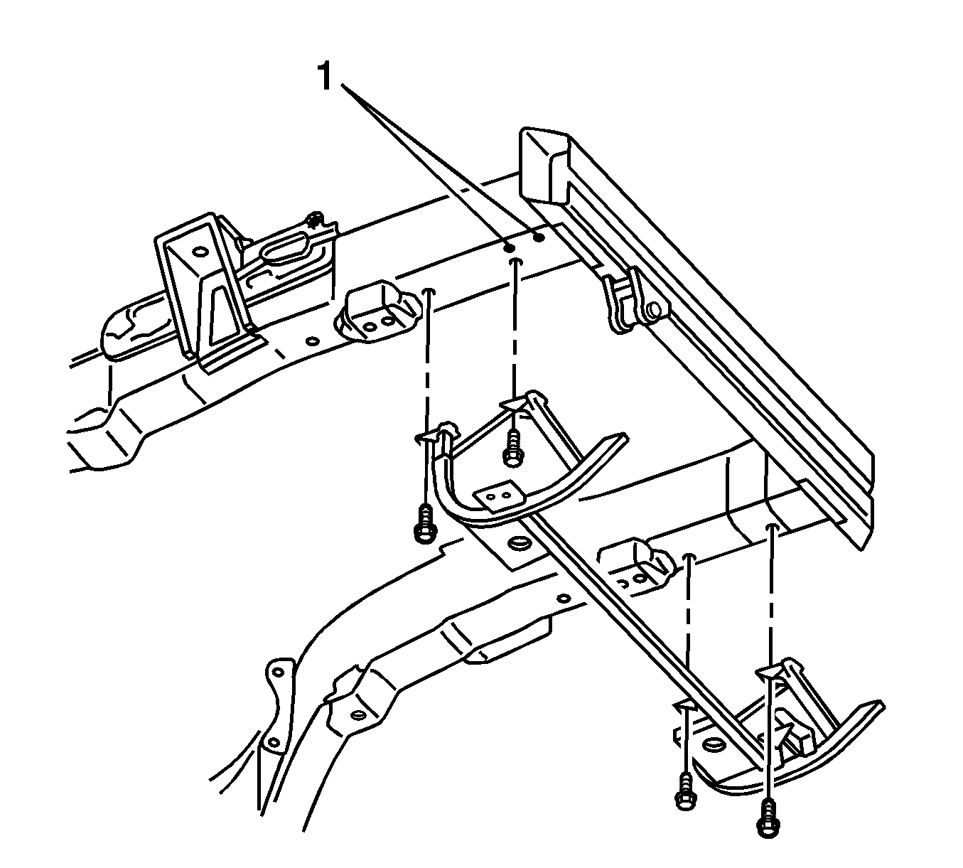
- Locate and drill a 6 mm (1/4 in) pilot hole (1) directly below the broken hood stud.
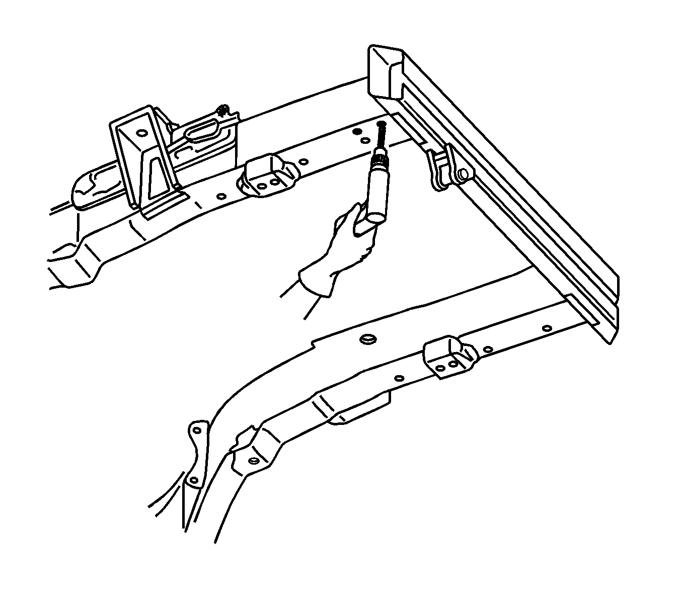
- Drill a 25 mm (1 in) hole directly below the broken hood stud.
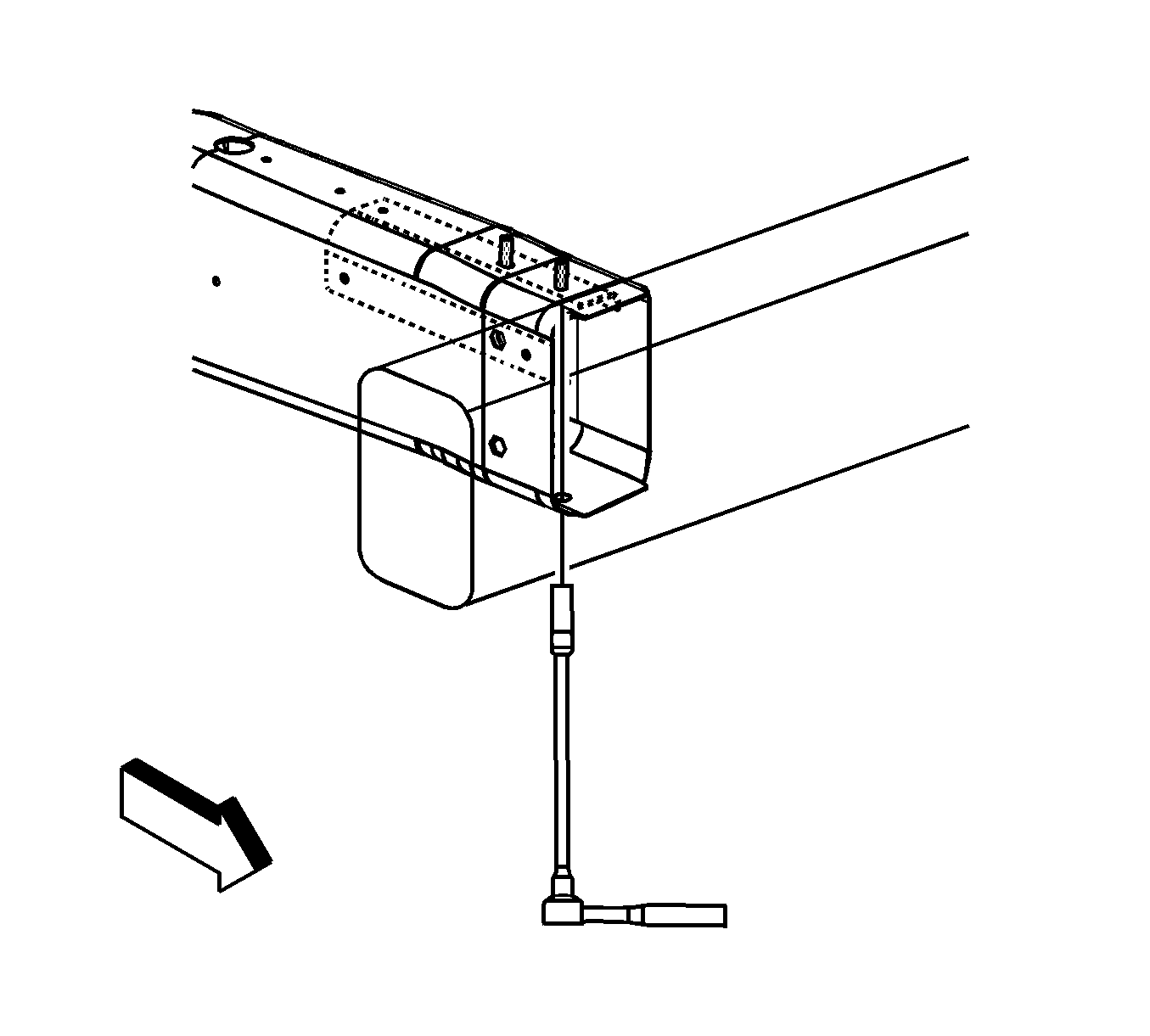
- Install a socket and extension through the bottom of the frame rail directly under the broken hood stud.
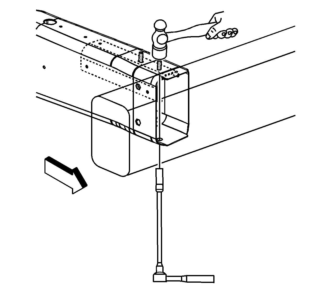
- Using a hammer, tap the broken hood stud into the socket.
- Remove the broken hood stud.
Caution: Refer to Approved Equipment for Collision Repair Caution in the Preface section.
Installation Procedure
- Install a replacement bolt through the bottom of the frame rail.
- Install a retaining clip to the new bolt.
- Install the hood hinge.
- Paint the repaired area. Refer to Basecoat/Clearcoat Paint Systems .
- Apply the sealers and the anti-corrosion materials to the repaired area, as necessary. Refer to Anti-Corrosion Treatment and Repair .
- Install all related panels and components.
- Connect the negative battery cable. Refer to Battery Negative Cable Disconnection and Connection .
- Enable the SIR system. Refer to SIR Disabling and Enabling .

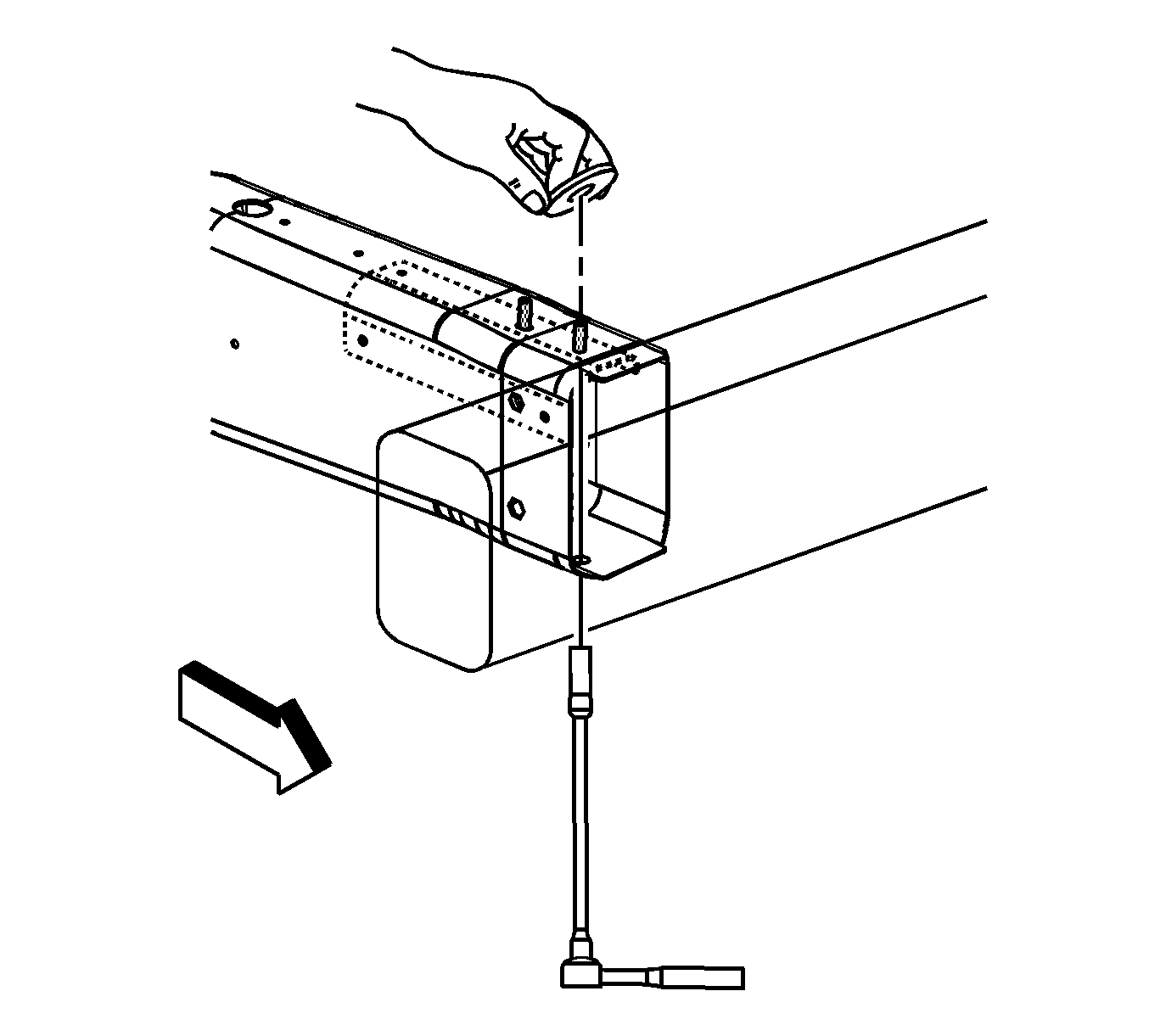
Hood Plate Stud Replacement Z06
Removal Procedure
The hood anchor plate assembly is riveted to the inside of the front frame rail. Access to the hood plate assembly would require the removal of the welded front bumper bar. A procedure was developed for the replacement of a broken hood stud without removing the front bar.
- Disable the SIR system. Refer to SIR Disabling and Enabling .
- Disconnect the negative battery cable. Refer to Battery Negative Cable Disconnection and Connection .
- Remove all related panels and components.
- Note the location and remove the sealers and anti-corrosion materials from the repair area, as necessary. Refer to Anti-Corrosion Treatment and Repair .
- Remove the hood hinge. Refer to Hood Hinge Replacement .
- Locate the 2 pilot holes (1) directly below the front and rear hood studs.
- Drill a 25 mm (1 in) hole directly below the broken hood stud.
- Install a socket and extension through the bottom of the frame rail directly under the broken hood stud.
- Using a hammer, tap the broken hood stud into the socket.
- Remove the broken hood stud.
Caution: Refer to Approved Equipment for Collision Repair Caution in the Preface section.


Installation Procedure
- Install a replacement bolt through the bottom of the frame rail.
- Install a retaining clip to the new bolt.
- Install the hood hinge. Refer to Hood Hinge Replacement .
- Paint the repaired area. Refer to Basecoat/Clearcoat Paint Systems .
- Apply the sealers and the anti-corrosion materials to the repaired area, as necessary. Refer to Anti-Corrosion Treatment and Repair .
- Install all related panels and components.
- Connect the negative battery cable. Refer to Battery Negative Cable Disconnection and Connection .
- Enable the SIR system. Refer to SIR Disabling and Enabling .

Important: Replacement fasteners used with the Z06 aluminum frame requires a tin-zinc coating to prevent galvanic corrosion.

