Tools Required
| • | J 42640 Steering Column Lock Pin |
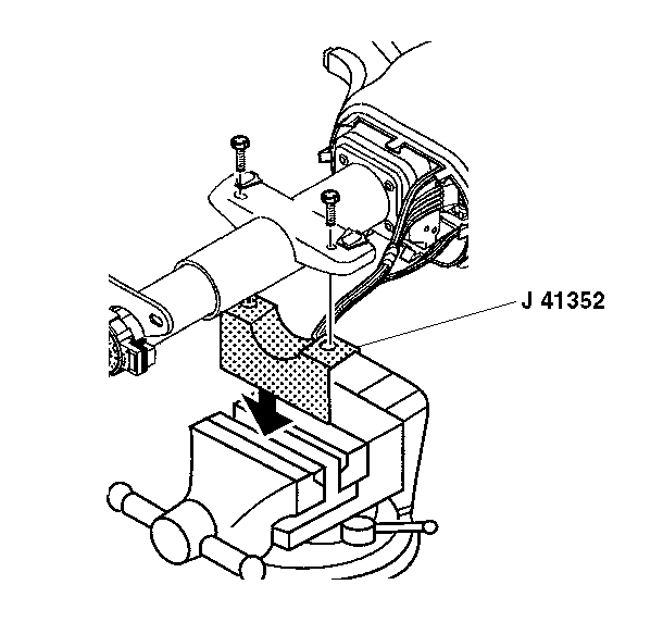
| • | J 41352 Modular Column Holding Fixture |
Removal Procedure
- Disable the SIR system. Refer to SIR Disabling and Enabling .
- Turn the steering wheel far enough to the left to gain access to the upper coupling bolt.
- Remove the upper coupling bolt.
- Turn the steering wheel back to the right until the wheels are in a straight ahead position. Lock the steering column.
- Insert J 42640 into the steering column access hole in order to lock the steering column. This will maintain the correct orientation.
- Remove the trim panel from the driver knee bolster. Refer to Driver Knee Bolster Panel Replacement .
- Remove the driver knee bolster bracket. Refer to Driver Knee Bolster Panel Replacement .
- Disconnect the electrical connectors from the instrument panel (I/P) wiring harness.
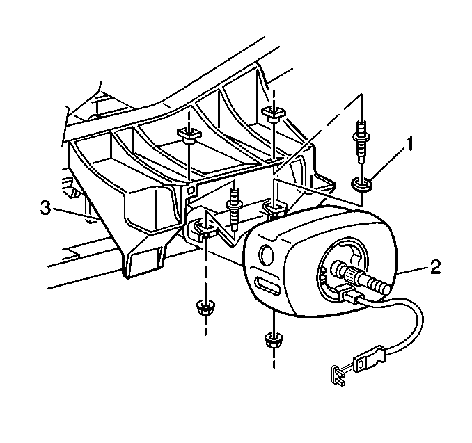
- Remove the nuts from lower steering column support plate (1).
- Remove the upper steering column bracket nuts from the upper reinforcement assembly (3).
- Slide the steering column (2) off of the intermediate shaft.
- Remove the steering column (2) from the vehicle.
- Install the steering column onto J 41352 .
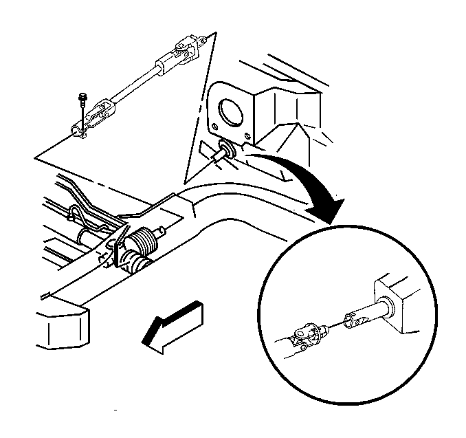
Important: If the steering column connectors are disconnected with the ignition in the ON position, the BCM will enter a fail enable mode and prevent steering column lock operation. The PCM will also inhibit vehicle motion by disabling fuel. To clear the BCM fail enable mode, disconnect the BCM fuse #25 for 15 seconds.
Notice: The wheels of the vehicle must be straight ahead and the steering column in the LOCK position before disconnecting the steering column or intermediate shaft from the steering gear. Failure to do so will cause the SIR coil assembly to become uncentered, which may cause damage to the coil assembly.
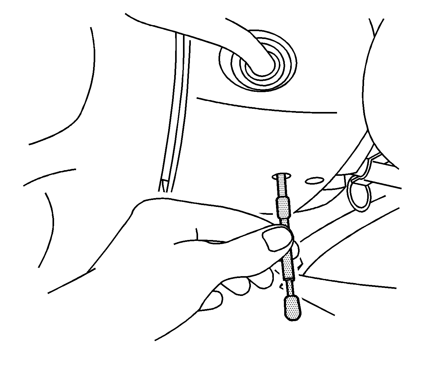
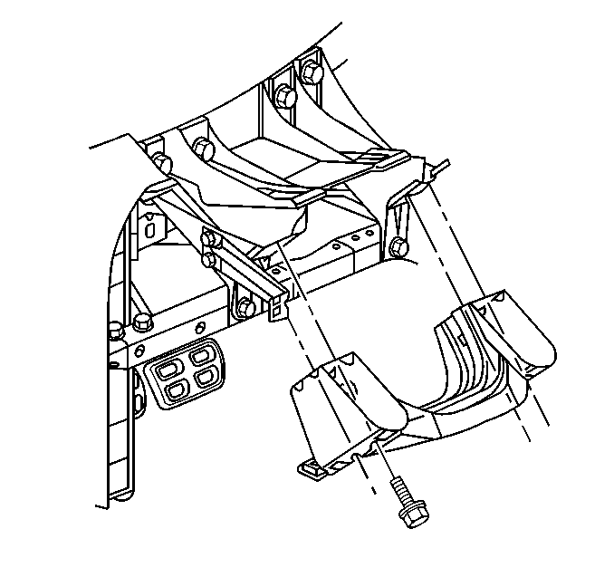
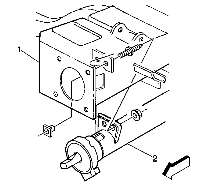
Notice: Once the steering column is removed from the vehicle, the column is extremely susceptible to damage. Dropping the column assembly on the end could collapse the steering shaft or loosen the plastic injections, which maintain column rigidity. Leaning on the column assembly could cause the jacket to bend or deform. Any of the above damage could impair the columns collapsible design. Do NOT hammer on the end of the shaft, because hammering could loosen the plastic injections, which maintain column rigidity. If you need to remove the steering wheel, refer to the Steering Wheel Replacement procedure in this section.
Rotate the steering column clockwise as the bottom of the steering column reaches the reinforcement assembly. This will allow the telescoping steering column motor and the steering wheel position sensor room to clear the I/P brace.
Installation Procedure
- Remove the steering column from J 41352 .
- Position the steering column assembly (2) into the vehicle and insert the lower steering shaft assembly into the upper coupling of the intermediate shaft.
- Install the cross car locating bushing (1) on the right hand mounting stud.
- Install the upper steering column bracket nuts to the upper reinforcement assembly (3).
- Install the nuts to the lower steering column support plate (1).
- Turn the steering wheel far enough to the left to gain access to the upper coupling of the intermediate shaft.
- Install the upper coupling bolt.
- Connect all the electrical connectors to the I/P wiring harness.
- Remove J 42640 from the steering column.
- Install the driver knee bolster bracket (1). Refer to Driver Knee Bolster Panel Replacement .
- Install the driver knee bolster trim panel. Refer to Driver Knee Bolster Panel Replacement .
- Enable the SIR system. Refer to SIR Disabling and Enabling .


Notice: Refer to Fastener Notice in the Preface section.
Tighten
Tighten the nuts to 24 N·m (18 lb ft).

Tighten
Tighten the nuts to 24 N·m (18 lb ft).

Tighten
Tighten the bolt to 48 N·m (35 lb ft).

