Special Tools
J 37088-A Fuel Line Disconnect Tool
Removal Procedure
- Disconnect the negative battery cable. Refer to Battery Negative Cable Disconnection and Connection .
- Drain the fuel tank. Refer to Fuel Tank Draining .
- Remove the right rear wheelhouse panel. Refer to Rear Wheelhouse Panel Liner Replacement .
- If automatic transmission, remove the driveline support assembly. Refer to Driveline Support Assembly Replacement .
- Remove the evaporative emission (EVAP) canister access cover.
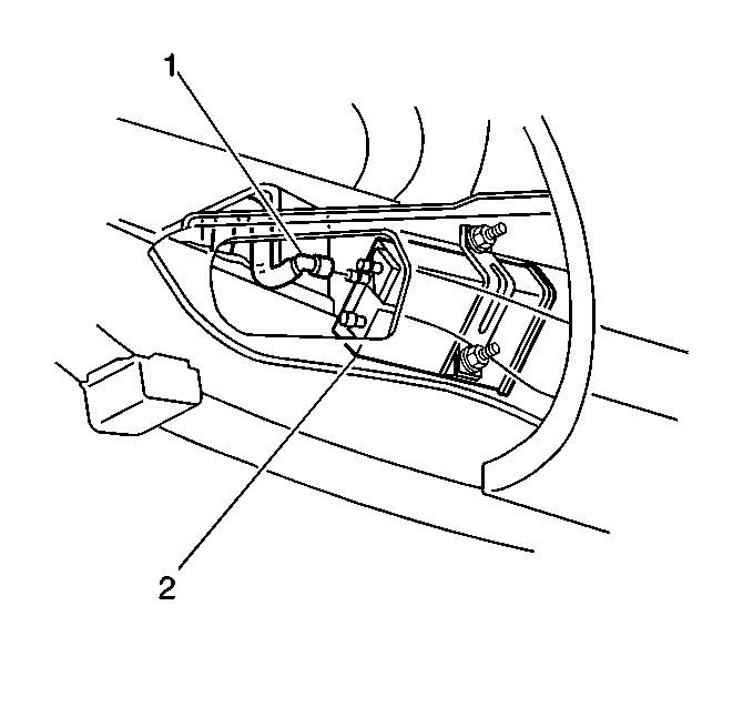
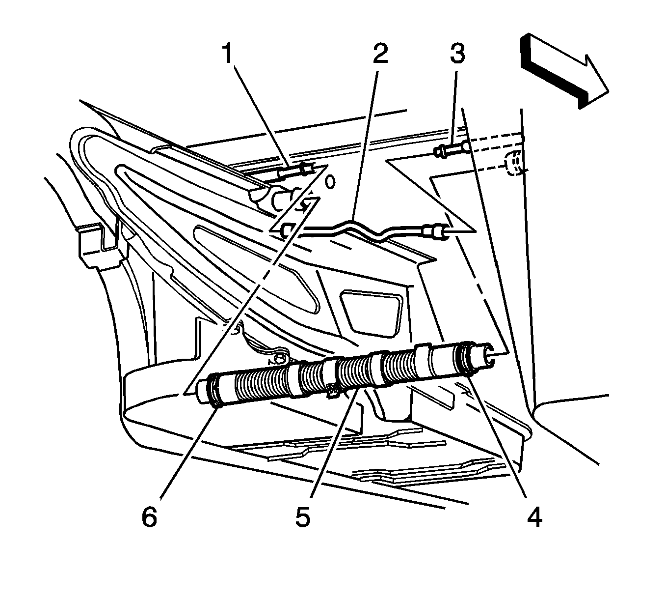
- Disconnect the fill limit vent valve (FLVV) hose (1) at the EVAP canister (2).
- Disconnect the fuel pump module harness connector.
- Remove the crossover tube from the clamp located above the transmission.
- Disengage the crossover tube connector position assurance (CPA) retainer by pulling the tab (1) outward and rotate.
- Rotate crossover tube collar counterclockwise to disengage.
- Disconnect the crossover tube (5) from the right fuel tank by pulling the tube straight out of the fuel tank connection.
- Disconnect the EVAP crossover pipe (2) quick connect fitting at the right fuel tank.
- Cap the EVAP pipe to prevent system contamination.
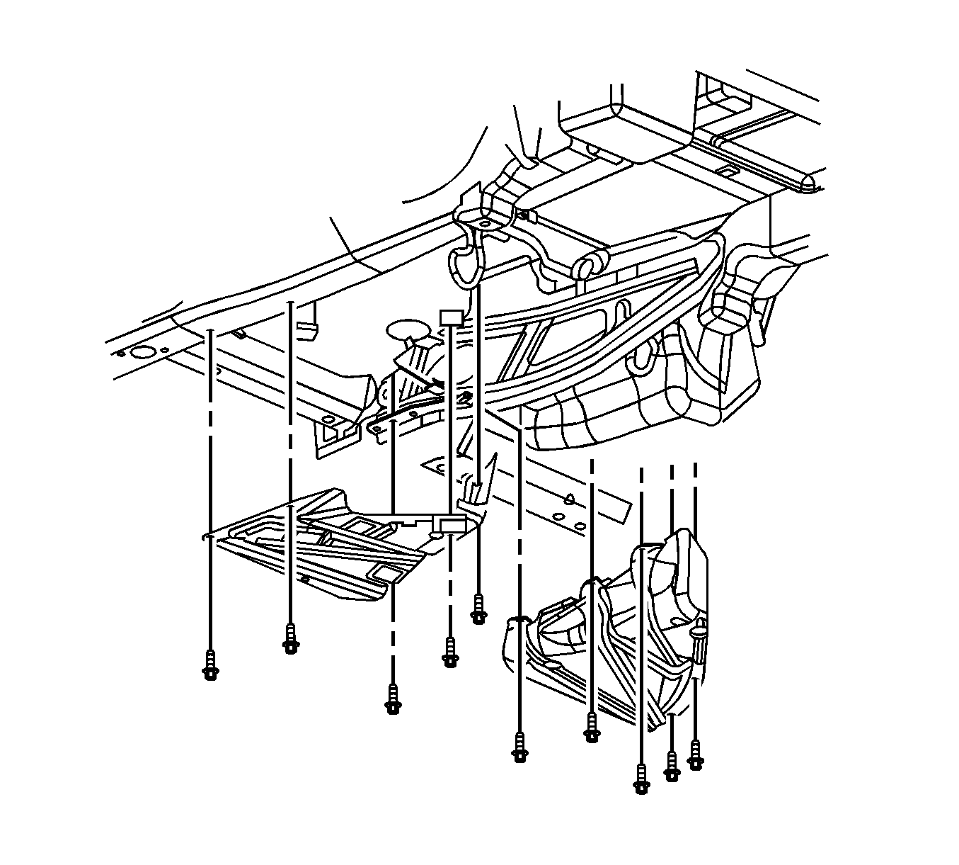
- Remove the fuel tank strap mount bolts.
- Remove the fuel tank strap from the vehicle.
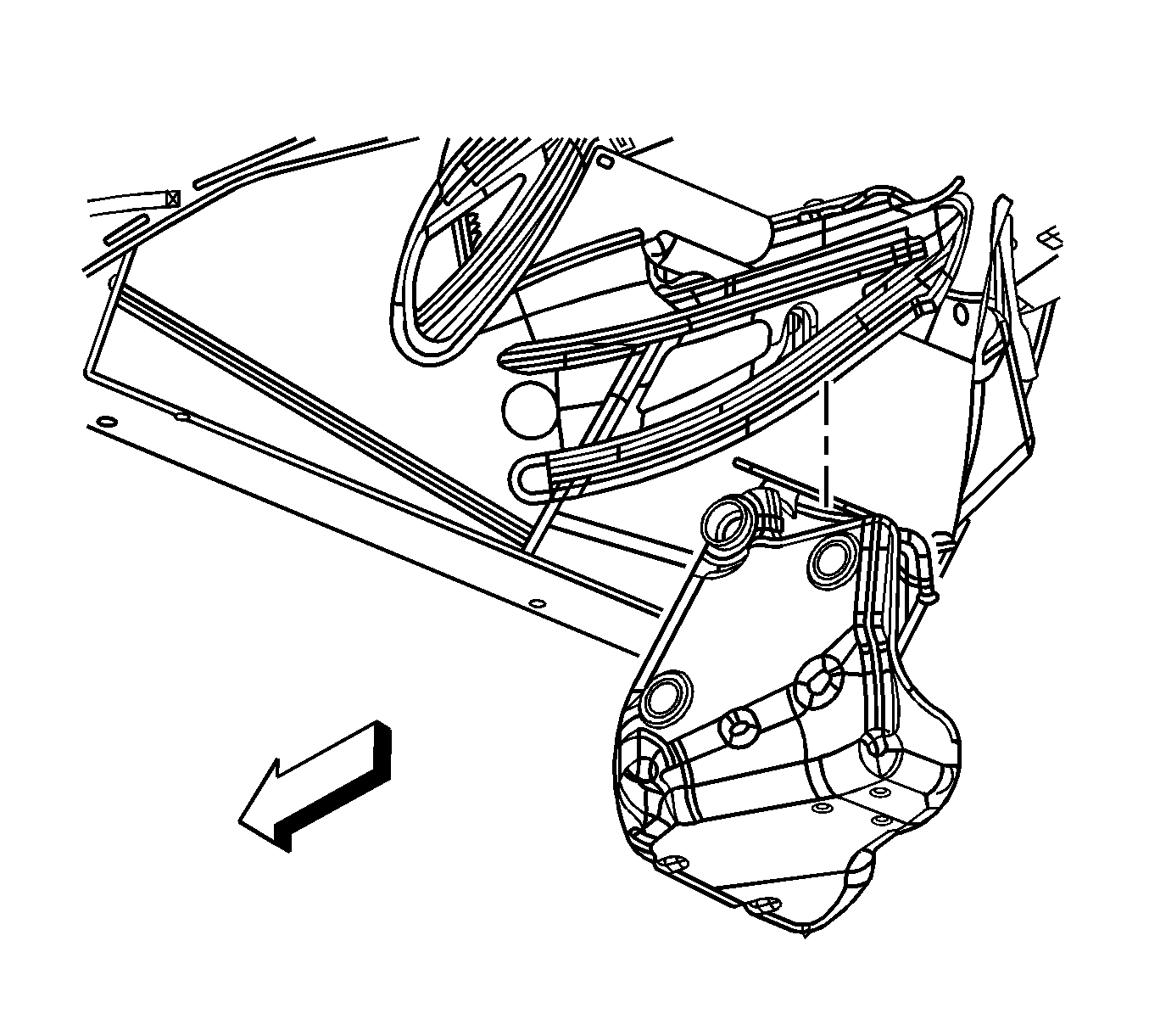
- Remove the fuel tank.
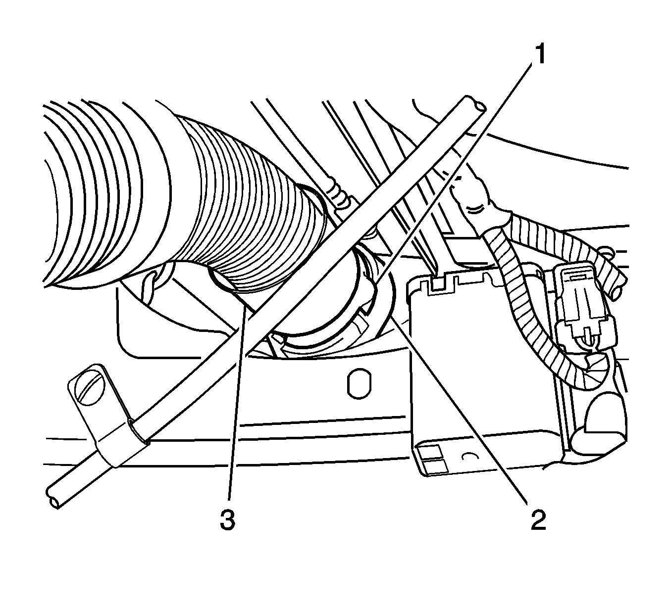
Important: The crossover tube CPA is released when the latch disengages from the tank connection groove.
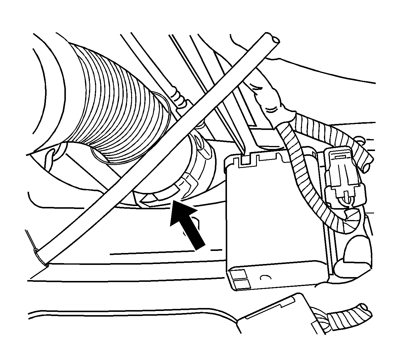
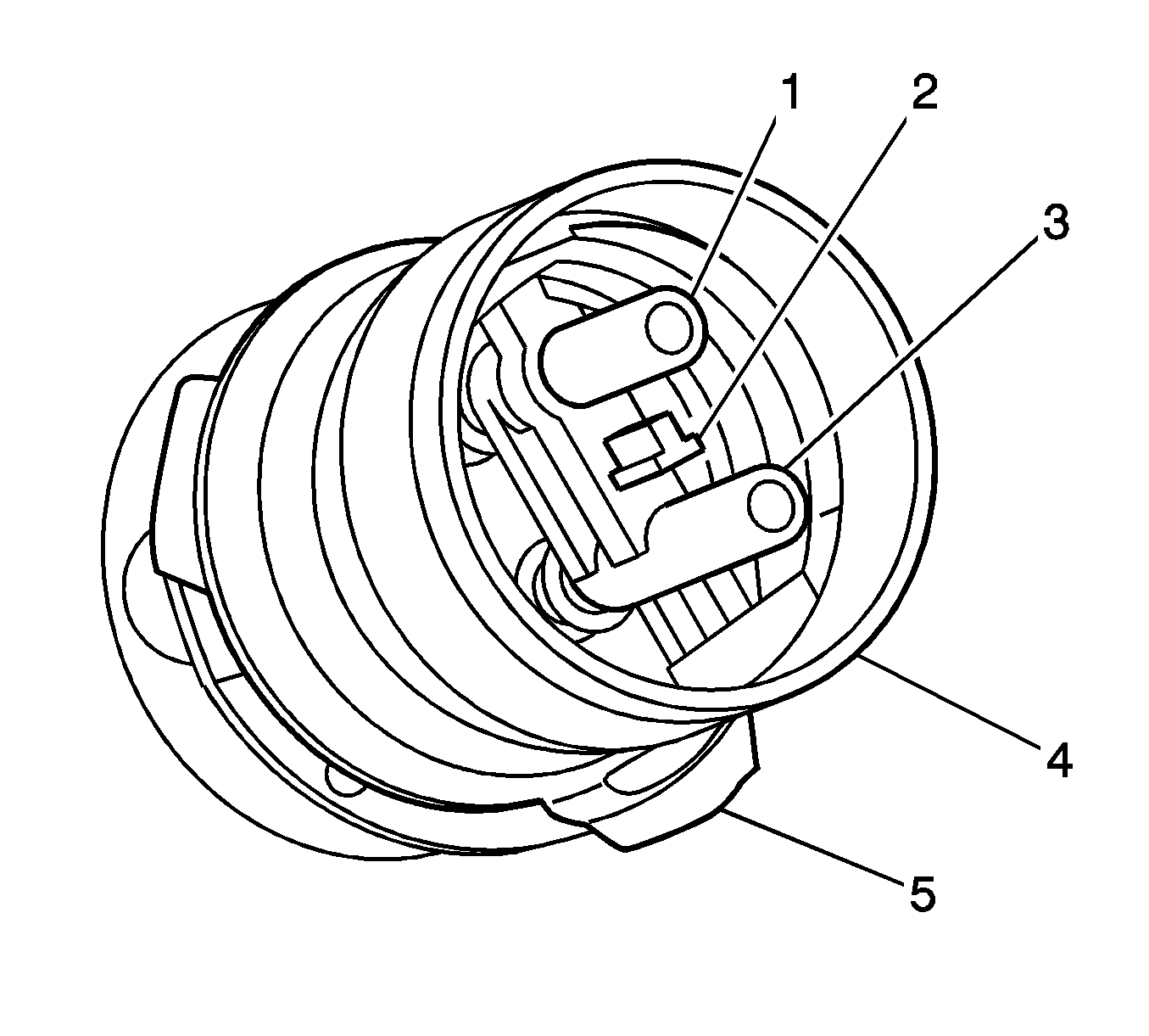
Important: Take care not to disturb the internal O-rings in the fuel tank connections.
Installation Procedure
- Install the fuel tank.
- Install the fuel tank strap to the vehicle.
- Install the fuel tank strap bolts.
- Remove the cap from the EVAP pipe.
- Connect the EVAP crossover pipe (2) quick connect fitting at the right fuel tank.
- Inspect the O-rings for damage.
- Lubricate the crossover tube O-ring mating surfaces (1-4) with GM P/N 1051717 (Canadian P/N 5728223) rubber lubricant.
- Connect the crossover tube to the right fuel tank using the features previously noted.
- Rotate the crossover tube collar (3) clockwise to engage the tangs.
- Rotate the crossover tube CPA retainer counterclockwise past the collar latching tang and push the tab (1) into the locked position.
- Test the crossover tube to fuel tank connection by attempting to rotate the crossover tube collar counterclockwise.
- Tighten the fuel tank strap bolts.
- Snap the crossover tube into the clamp located above the transmission.
- Connect the fuel pump module harness connector.
- Connect the FLVV hose (1) at the EVAP canister (2).
- Install the EVAP canister access cover.
- If automatic transmission, install the driveline support assembly. Refer to Driveline Support Assembly Replacement .
- Install the right rear wheelhouse panel. Refer to Rear Wheelhouse Panel Liner Replacement .
- Lower the vehicle.
- Refuel the fuel tank.
- Connect the negative battery cable. Refer to Battery Negative Cable Disconnection and Connection .
- Perform the following procedure in order to test for leaks:
- Program the transmitters. Refer to Transmitter Programming .


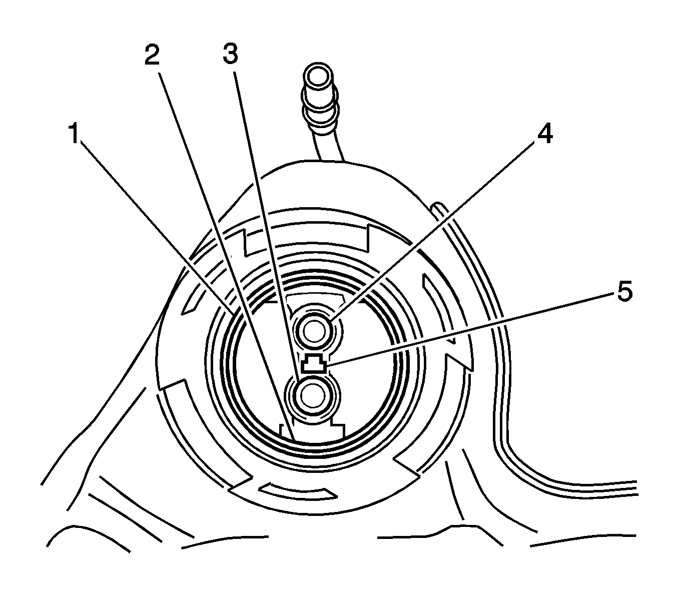
Lubricate the crossover tube to fuel tank connection O-rings (1-4) with GM P/N 1051717 (Canadian P/N 5728223) rubber lubricant.

Important: Note the location of the T-shaped alignment feature (5) between the jet pump feed/return pipes connector.
Important:
• Note the T-shaped alignment feature on the crossover tube. • The crossover tube will not fully seat into the fuel tank if the jet pump lines are misaligned.
Important: The crossover tube collar tangs will not latch if misalignment exists.

Important: If the CPA retainer is locked into position, the crossover tube collar will not rotate.
Notice: Refer to Fastener Notice in the Preface section.

Tighten
Tighten the bolts to 25 N·m (18 lb in).

| 22.1. | Turn ON the ignition switch for 2 seconds. |
| 22.2. | Turn OFF the ignition for 10 seconds. |
| 22.3. | Turn ON the ignition. |
| 22.4. | Inspect for fuel leaks. |
Specification
| • | Fuel pump on: 400 kPa (58 psi) |
| • | Fuel pump off: 359 kPa (52 psi) |
