Wheel Drive Shaft Inner Joint and Boot Replacement NON Z06/Z51
Tools Required
| • | J 35910
Drive Axle Seal Clamp Pliers |
Removal Procedure
This procedure is to be performed only after the drive shaft has been removed from the vehicle; for the removal procedure refer to
Wheel Drive Shaft Replacement
.
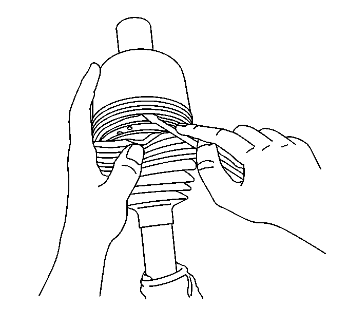
- Wrap a shop towel around the axle shaft.
- Place the wheel drive shaft horizontally in a bench vise.
- Using
J 46588
, remove the large seal retaining clamp from the CV joint seal.
- Remove the small seal retaining clamp from the joint seal.
Use a side cutter or other suitable tool and discard the clamp.
- Separate the seal from the joint outer race at the large diameter end.
- Position the seal behind the joint face.
- Position the wheel drive shaft vertically in the bench vise so the inner joint is up.
- Slide the joint outer race down toward the vise.
- Disengage the outer race retaining ring.
| 9.1. | Insert a small flat-bladed screwdriver between the retaining ring and the outer race. |
| 9.2. | Remove the retaining ring from the outer race. |
| 9.3. | Position the retaining ring along the axle shaft away from the outer race. |
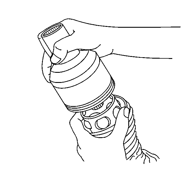
Important: The balls may fall out of the cage and inner race when the outer race is removed.
- Remove the outer race from the axle shaft.
| 10.1. | Use the seal to catch any balls which are not retained by grease. |
| 10.2. | Lift the outer race off the axle shaft. |
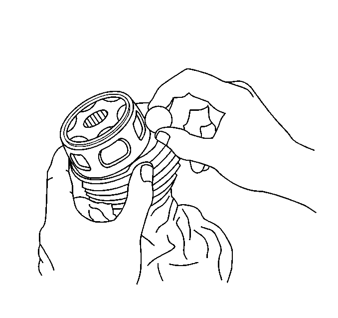
- Remove any remaining balls from the cage and inner race.
Remove any balls caught by the seal.
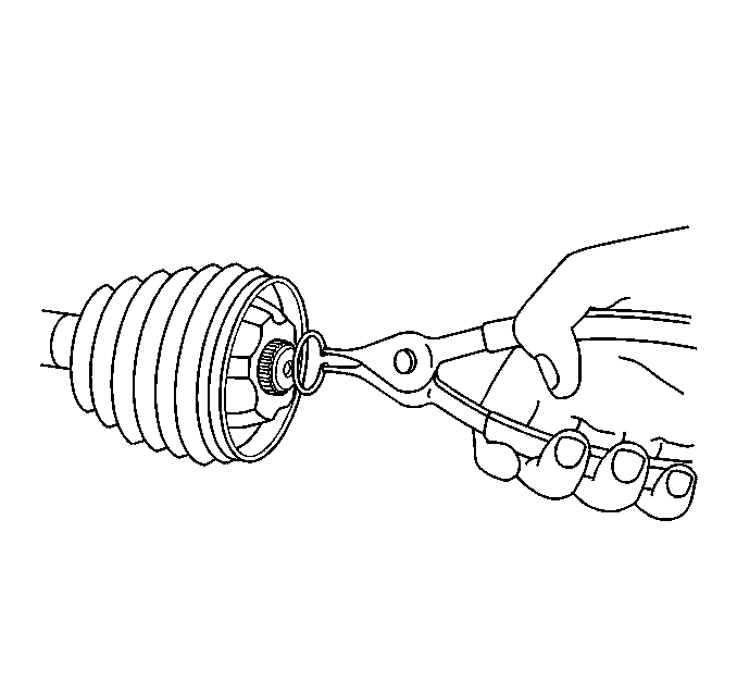
- Position the wheel drive shaft horizontally in the bench vise.
- Remove the outer race retaining ring from the axle shaft.
- Remove the snap ring from the axle shaft.
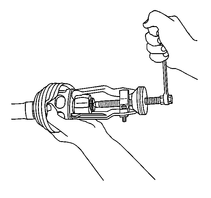
- Align the cage lands with the inner race ball tracks.
- Reposition the cage along the axle shaft away from the inner race.
- Wipe the grease from the inner race.
- Remove the inner race from the axle shaft using a 3 jaw puller.
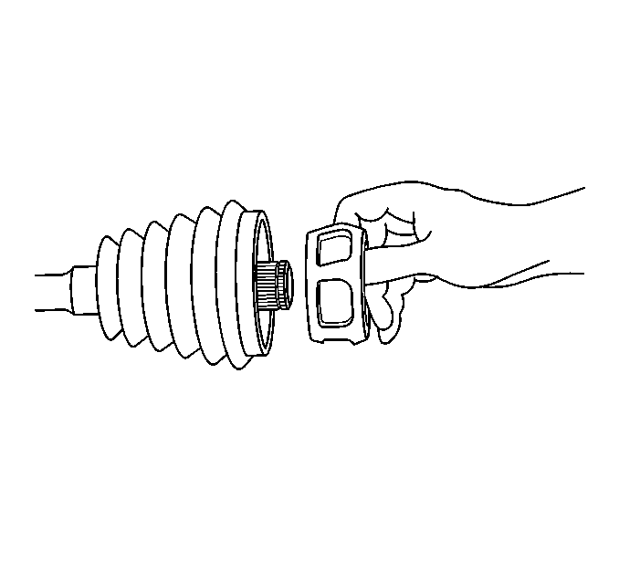
- Remove the cage from the axle shaft.
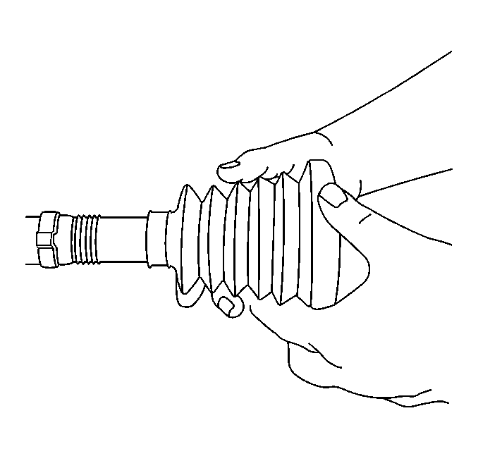
- Remove the seal from the axle shaft.
- Remove the wheel drive shaft from the bench vise.
Important: All traces of old grease and any contaminates must be removed.
- Clean the following thoroughly with clean solvent:
| • | The axle shaft exposed end |
- Thoroughly air dry all the parts.
Installation Procedure
Notice: Wheel drive shaft boots, seals and clamps should be protected
from sharp objects any time service is performed on or near the wheel drive
shaft(s). Damage to the boot(s), the seal(s) or the clamp(s) may cause lubricant
to leak from the joint and lead to increased noise and possible failure
of the wheel drive shaft.

- Wrap a shop towel around the axle shaft.
- Place the wheel drive shaft horizontally in a bench vise.
- Install a new small seal retaining clamp onto the wheel drive shaft.
- Install the seal onto the axle shaft.

- Install the cage onto the axle shaft so the smaller diameter end faces the vise.
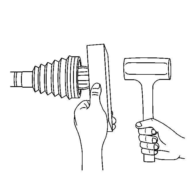
Important: The inner race spline relief must face away from the end of the axle shaft.
- Install the inner race onto the axle shaft.
| 6.1. | Engage the inner race splines onto the axle shaft splines. |
Be sure to install the inner race spline relief side onto the axle shaft first.
| 6.2. | Position a wood block squarely over the end of the inner race. |
| 6.3. | Use a hammer to begin to drive the inner race onto the axle shaft. |
| 6.4. | Reposition the wood block along the face of the inner race to avoid the axle shaft. |
| 6.5. | Work evenly around the inner race and continue to drive the inner race, until you feel the inner race seat fully onto the axle shaft. |
| 6.6. | Inspect to be sure that the axle shaft snap ring groove is exposed. |

- Install the snap ring to the axle shaft.
- Position the cage so the cage lands align with the inner race ball tracks.
- Install the cage onto the inner race.
- Position the cage windows to align with the inner race ball tracks.
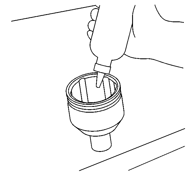
- Insert approximately 60 percent of the grease from the service kit into the outer race.
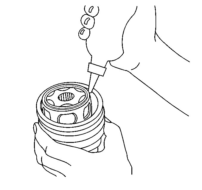
- Position the wheel drive shaft vertically in the bench vise so the inner joint end is up.
- Apply a small amount of the grease from the service kit to the cage windows and inner race ball tracks.
- Insert the remaining grease from the service kit into the seal.

- Install the outer race retaining ring onto the axle shaft.
Position the retaining ring below the
cage toward the vise.
- Install the balls through the cage windows to the inner race ball tracks.
Use the seal to keep the balls in position if necessary.

- Install the outer race onto the axle shaft.
| 17.1. | Be careful not to allow the grease in the outer race to leak out. |
| 17.2. | Align the outer race ball tracks to the balls. |
| 17.3. | Slide the outer race down over the balls. |
- Position the wheel drive shaft horizontally in the bench vise.
- Engage the outer race retaining ring.
| 19.1. | Slide the outer race toward the vise. |
| 19.2. | Insert the outer race retaining ring into the groove along the outer edge of the outer race. |
| 19.3. | Position the outer race retaining ring so the opening in the ring aligns with an outer race land (not a ball track). |
- Position the large diameter end of the seal onto the outer race.
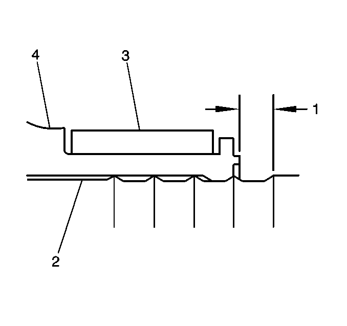
- Position the small seal retaining clamp (3) onto the neck of the seal (4).
- Position the seal and small retaining clamp to the axle shaft (2) as shown.
- Measure the distance (1) between the edge of the seal and the edge of the last axle shaft groove closing edge; adjust fit accordingly.
Specification
2.5 mm (0.10 in)
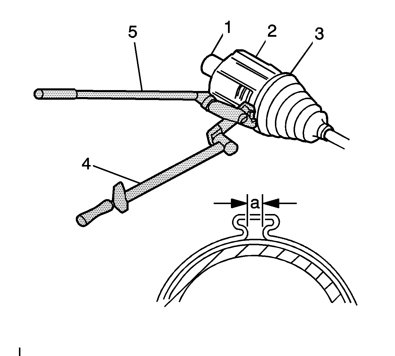
Important: Seal Clamp must be securely clamped in the seal groove and buckle securely fastened so as not to come loose and ride on the seal.
- Using the
J 42572
, crimp the small seal retaining clamp.
Tighten
Tighten the small seal retaining clamp until the gap width (a) between 1 and 4 mm (0.039 and 0.157 in).
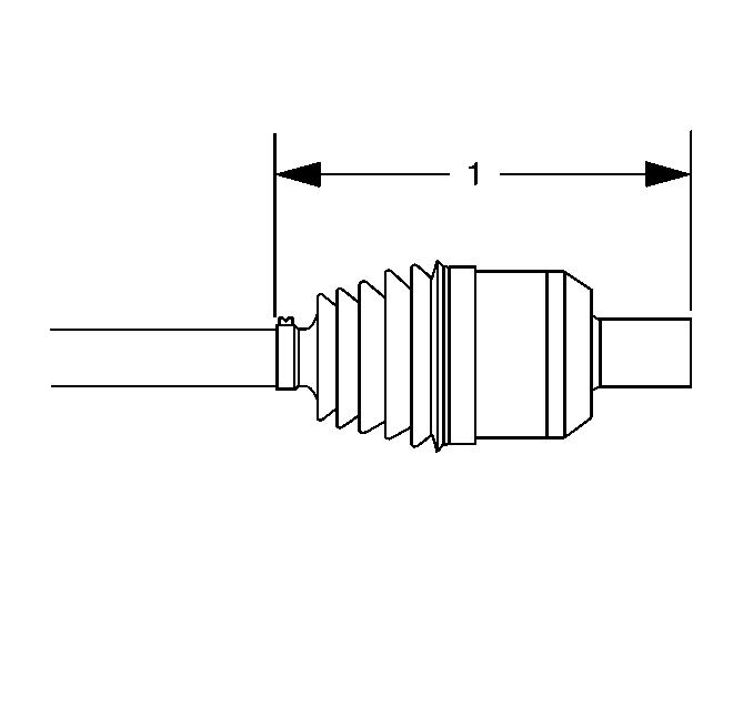
- Measure the distance (1) between the end of the seal and the end of the joint outer race. Adjust the plunging motion of the joint accordingly.
Specification
224-228 mm (8.82-8.98 in)
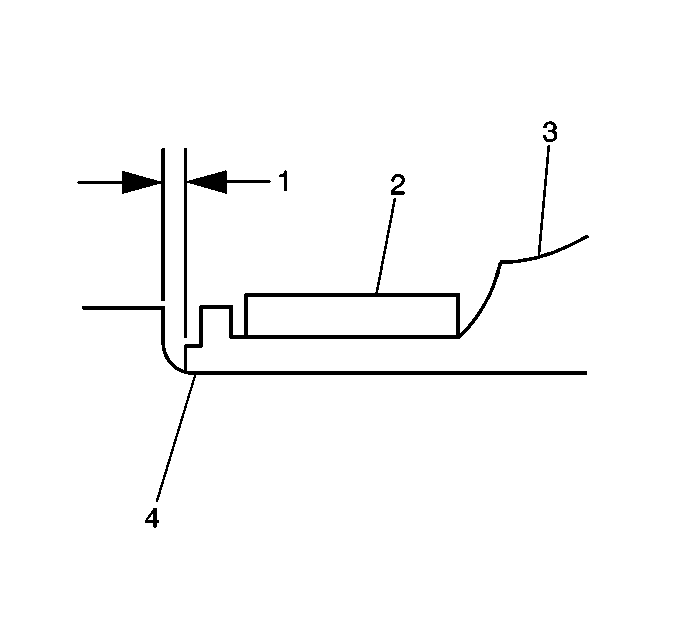
- Position the large seal retaining clamp (2) onto the seal (3).
- Position the seal and large retaining clamp to the joint outer race (4) as shown.
- Measure the distance (1) between the edge of the seal and the edge of the joint outer race last groove closing edge; adjust fit accordingly.
Specification
0.8 mm (0.03 in)
Important: The seal must not be dimpled, stretched or out of shape in any way.
- Inspect the seal for proper shape.
If the seal is NOT shaped correctly, equalize the pressure in the seal and shape the seal properly by hand.
- Inspect the seal for damage.
If the seal has been cut or punctured during assembly, you must discard and replace the seal.
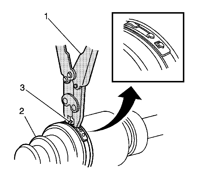
- Align the following items while latching:
| • | The wheel drive shaft inboard seal (2) |
| • | The large seal retaining clamp (3) |
- Using the
J 46588
, latch the large seal retaining clamp. Ensure that the latching tangs are fully engaged in the large seal clamp band.
- Remove the wheel drive shaft from the bench vise.
- Distribute the grease within the inner CV joint.
Plunge the joint back and forth four or five times.
- Inspect the inner CV joint and wheel drive shaft for smooth operation.
| 35.1. | Hold the wheel drive shaft vertically, with the outer joint at the bottom. |
| 35.2. | Rotate the wheel drive shaft four or five times in a circular motion. |
- Install the wheel drive shaft into the vehicle. Refer to
Wheel Drive Shaft Replacement
.
Wheel Drive Shaft Inner Joint and Boot Replacement With Z06/Z51
Tools Required
| • | J 8059
Snap Ring Pliers-Parallel Jaw |
| • | J 35910
Drive Axle Seal Clamp Pliers |
Disassembly Procedure
Important: In the following service procedures, DO NOT re-use the old clamps. Replace with new.
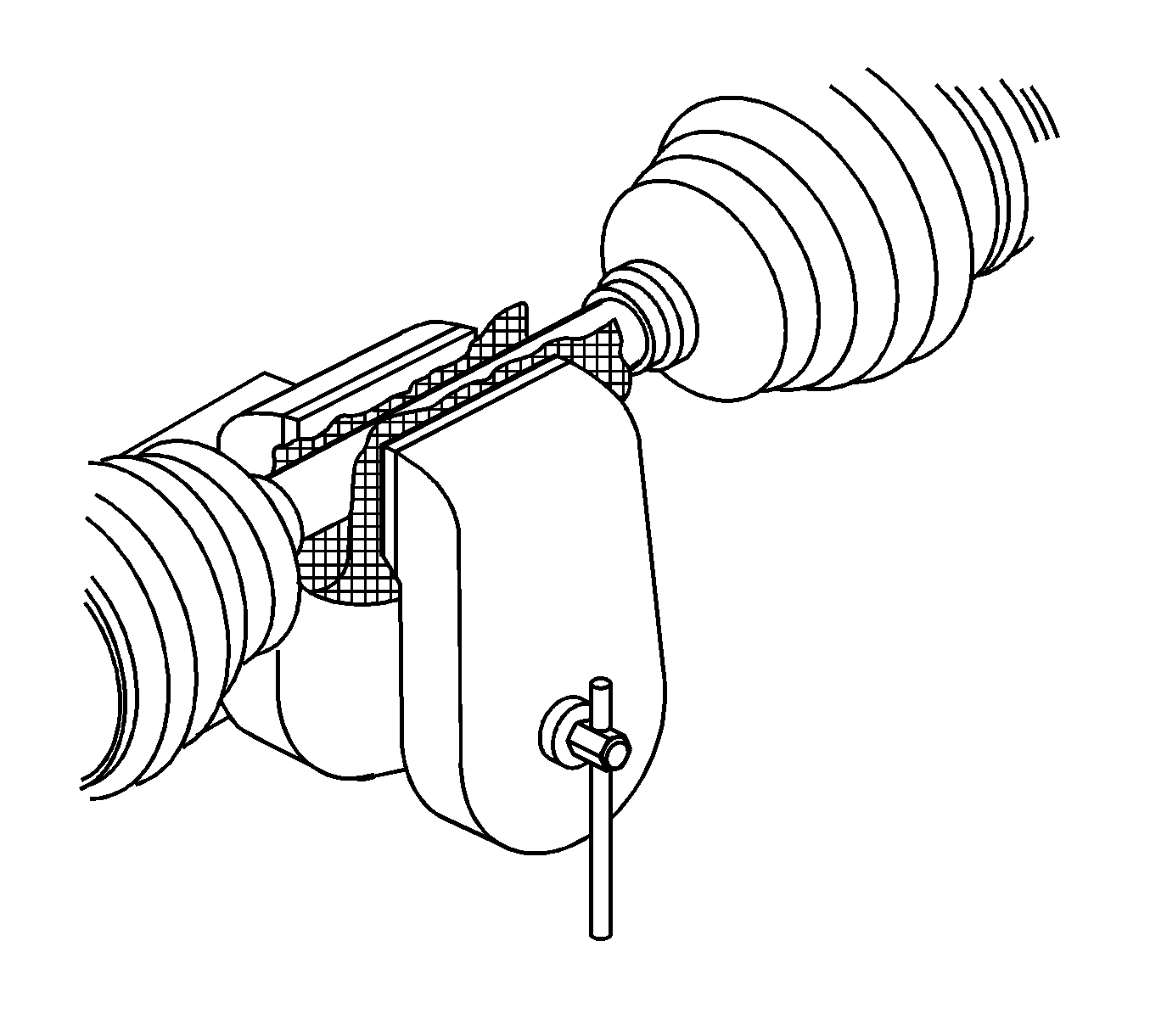
- Install wheel drive shaft bar in a soft jawed vise and clamp securely.
- Using side cutters, remove and discard the small seal clamp.
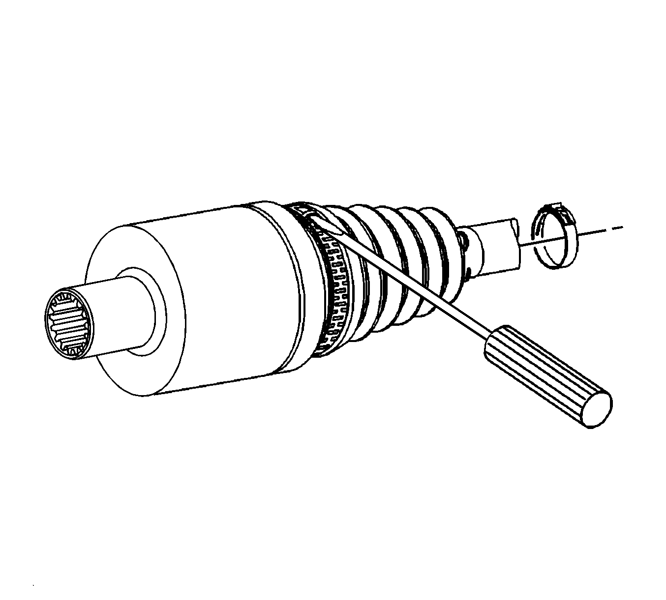
- Using a flat-bladed tool, remove large seal retaining clamp and discard the clamp.
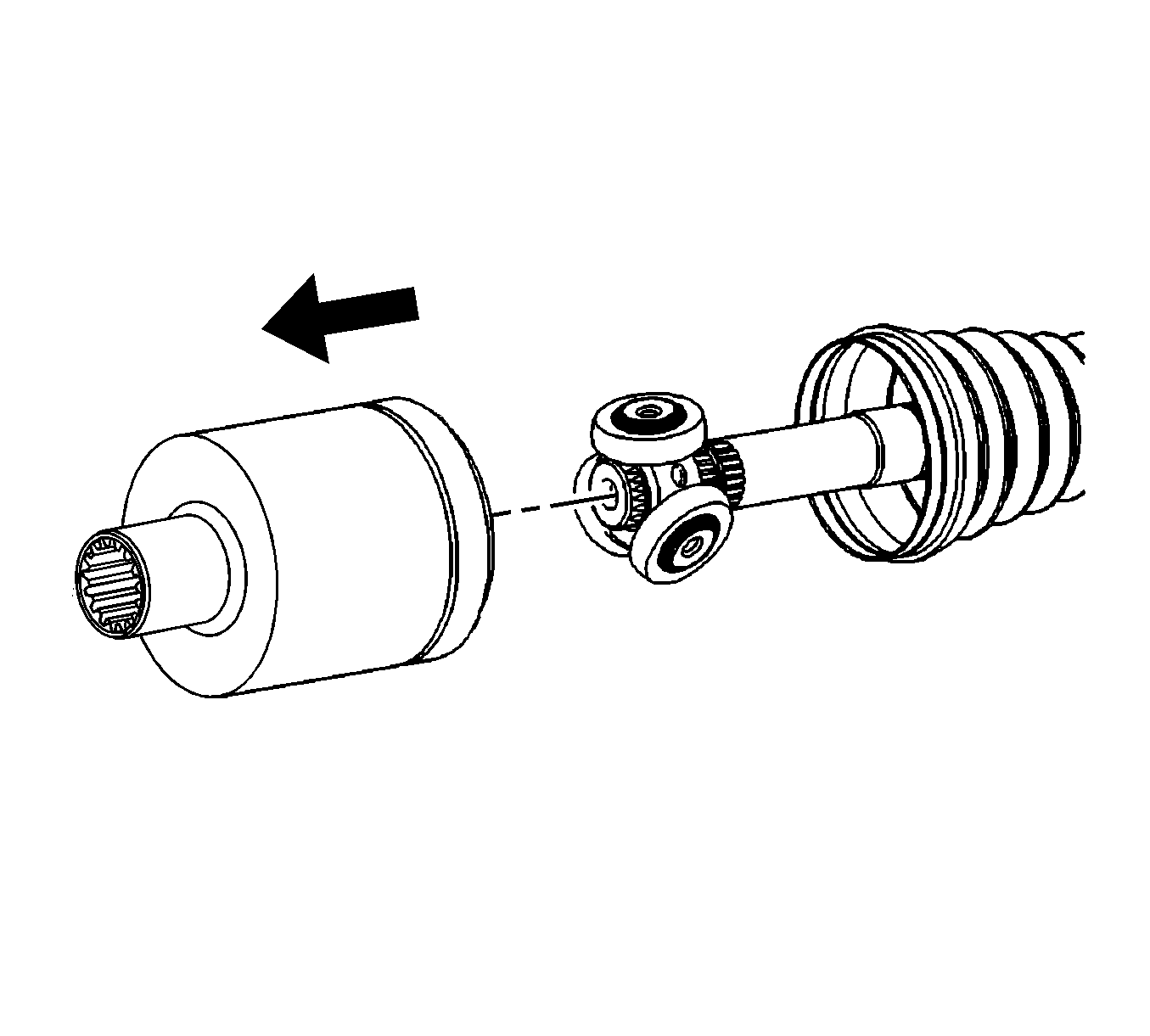
- Remove the large seal from the tripot housing and slide the seal away from the tripod housing.
- Remove the excess grease from the face of the tripot spider and the inside of the tripot housing.
Important: The rollers may fall off the spider assembly when the tripod joint is removed from the housing.
- Remove the spider assembly and the tripot housing from the wheel drive shaft.
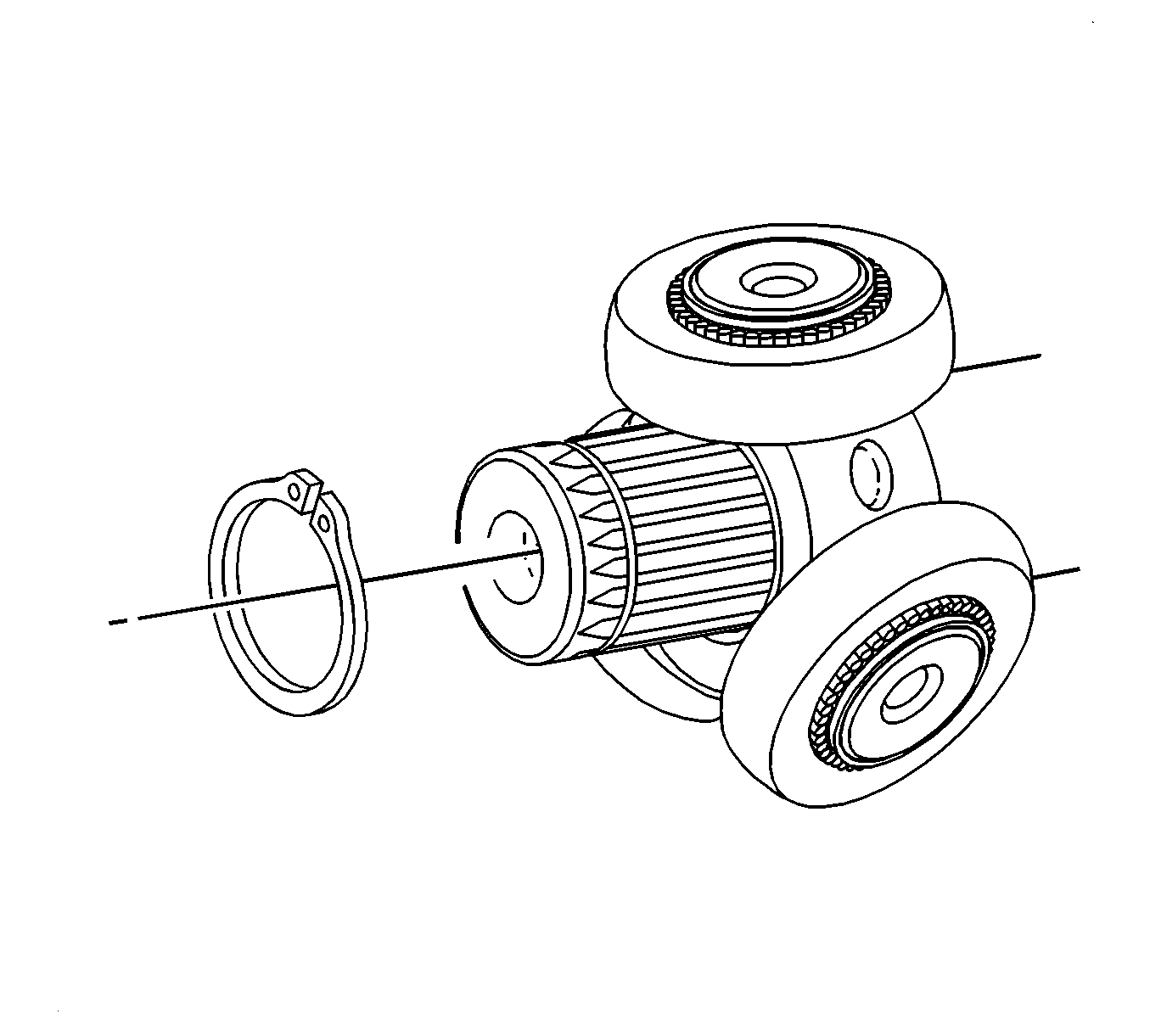
- Remove the rollers from the spider assembly.
- Using the
J 8059
, remove the snap ring from the wheel drive shaft.
- Remove the seal from the wheel drive shaft.
- Thoroughly clean all parts with a suitable solvent, removing all traces of grease and contaminants.
- Dry all parts with compressed air.
- Inspect the tripot joint components for unusual wear, cracks, and other damage. If any of the tripot joint components are damaged, replace the wheel drive shaft
Assembly Procedure

- Position the small seal retaining clamp (3) onto the neck of the seal (4).
- Position the seal and the small retaining clamp to the axle shaft (2) as shown.
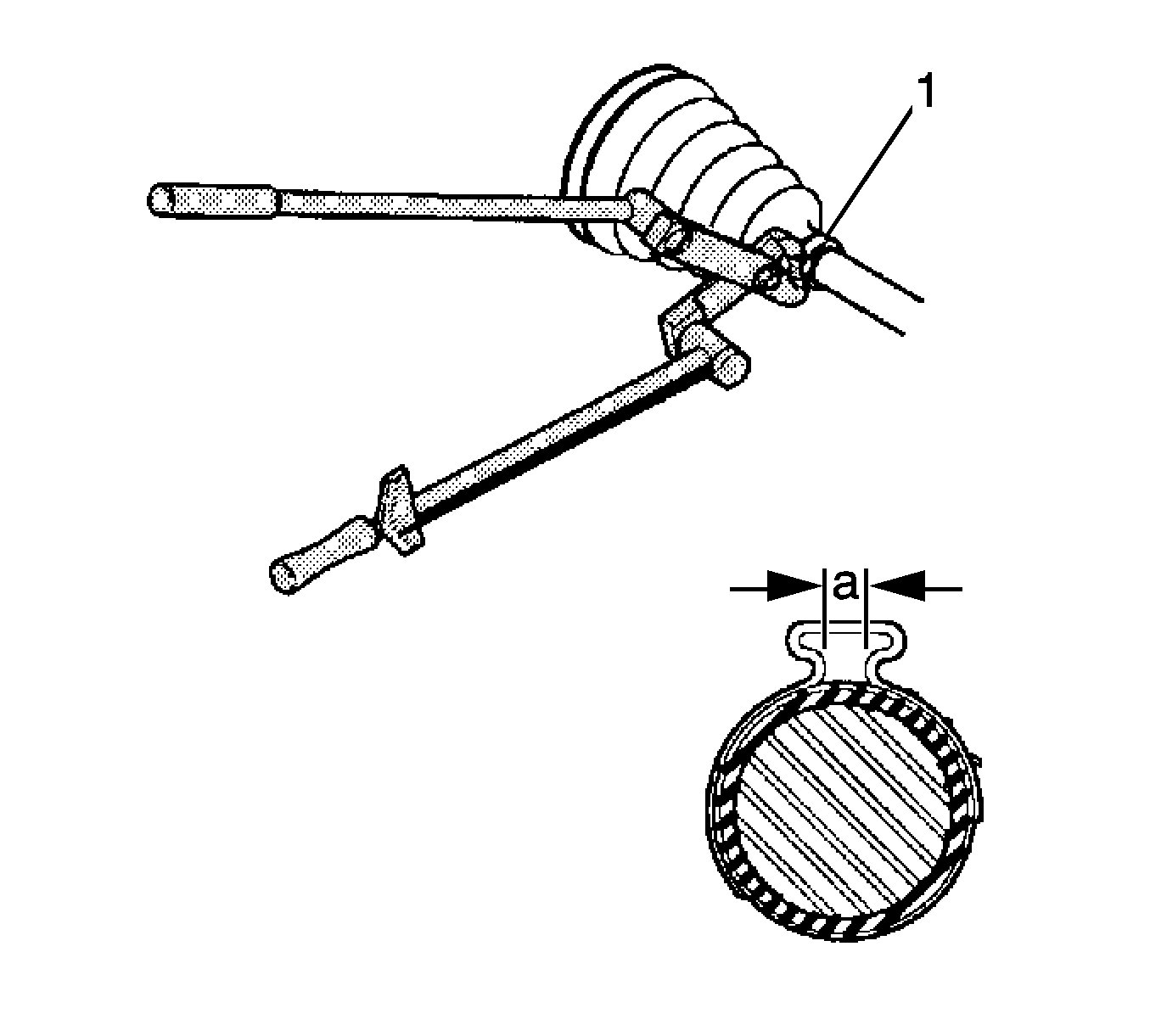
Important: The Seal clamp must be sercurely clamped in the seal groove and buckle securely fastened so as not to come loosen and ride the seal.
- Install the small seal clamp to the seal. Do not crimp the clamp.
- Using the
J 35910
, crimp the small seal retaining clamp until the measured gap width (a) is between 1 and 4 mm (0.038 and 0.157 in).

- Install the tripot spider assembly to the wheel drive shaft bar, until seated against shoulder.
- Using the
J 8059
, install the retaining ring in the groove of the wheel drive shaft.
- Place approximately half of the grease in the kit to the seal and place the remainder in the tripot housing.
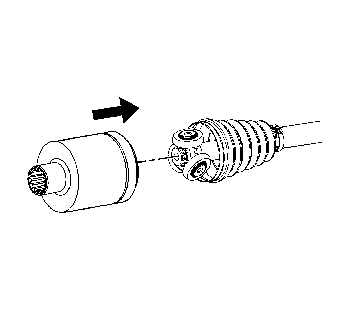
- Install the large clamp over the large diameter of the seal.
- Install the rollers on the spider assembly.
- Install the tripot housing to the tripot spider assembly on the wheel drive shaft bar.
- Slide the large diameter of the seal over the outside of the tripot housing and position the lip of the seal in the housing groove.

Important: Ensure that the seal is properly seated in the groove of the tripod housing.
- Position the large retaining clamp around the seal in the groove.
- Using the
J 35910
, crimp the large retaining clamp until the measured gap width (a) is between 1 and 4 mm (0.038 and 0.157 in).
- Rotate the housing in a circular motion to distribute the grease in the tripot joint.


