Fuel Injection Fuel Rail Assembly Replacement LS9
Removal Procedure
- Disconnect the negative battery cable. Refer to Battery Negative Cable Disconnection and Connection.
- Remove the upper intake cover. Refer to Upper Intake Manifold Sight Shield Replacement.
- Relieve the fuel system pressure. Refer to Fuel Pressure Relief
- Remove the front charge air cooler manifold. Refer to Charge Air Cooler Replacement
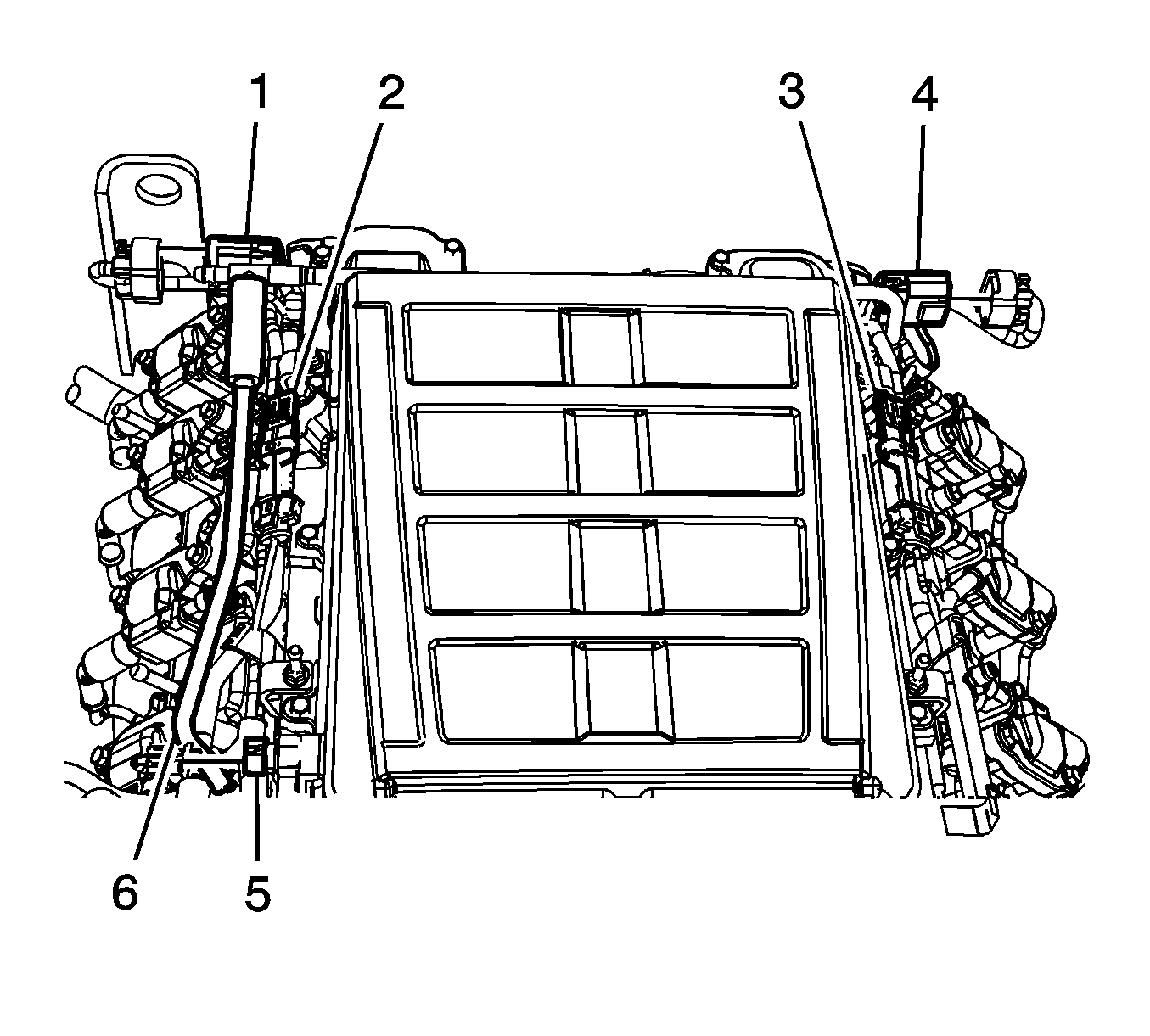
- Disconnect the fuel injection Harness connectors (1, 4).
- Disconnect the MAP sensor harness connector (2).
- Disconnect the supercharger air output sensor harness connector (3).
- Disconnect the intake temperature sensor harness connector (5).
- Disconnect and place aside the PCV tube (6).
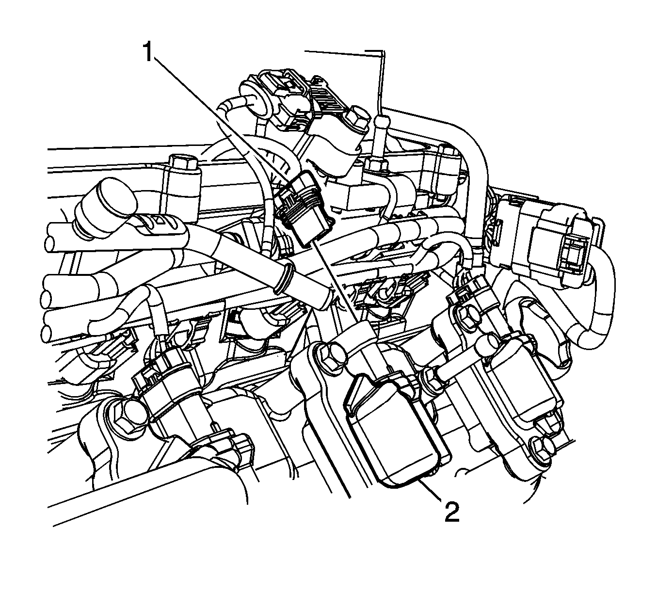
- Disconnect all 8 ignition coil harness connectors (1).
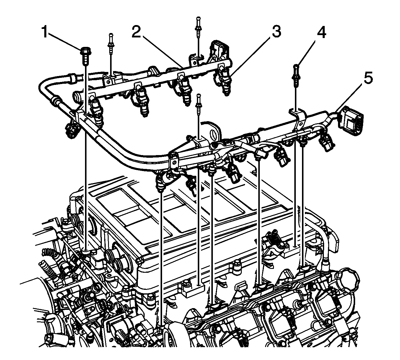
- Remove the front fuel rail fastener (1).
- Remove the fuel rail ball stud fasteners (2).
- Carefully disengage the fuel injectors (3) from the supercharger.
- Remove the fuel rail with the fuel injector harness (5) from the engine.
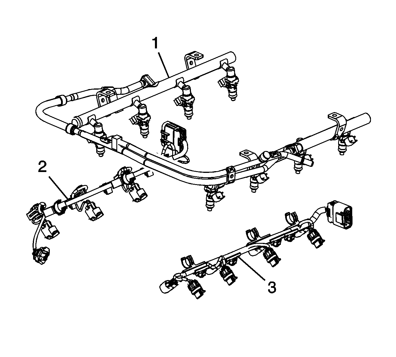
- Remove the fuel injection wiring harness (2, 3) from the fuel rail (1) and fuel injectors.
- If replacing the fuel rail of an injector. Refer to Fuel Injector Replacement.
Installation Procedure
- Install the fuel injectors. Refer to Fuel Injector Replacement.
- Install the fuel injection wiring harness ( 2, 3) to the fuel rail (1) and fuel injectors.
- Install the fuel rail with the fuel injector harness (5) to the engine.
- Carefully locate the fuel injectors (3) into the supercharger. Install the left side first and then the right side.
- Apply threadlock to the ball stud and fastener threads. Refer to Adhesives, Fluids, Lubricants, and Sealers.
- Instal the ball studs (4) and the forward fastener (1) and tighten to 10 N·m (89 lb in).
- Connect all 8 ignition coil harness connectors (1).
- Connect the fuel injection Harness connectors (1, 4).
- Connect the MAP sensor harness connector (2).
- Connect the supercharger air output sensor harness connector (3).
- Connect the intake temperature sensor harness connector (5).
- Connect the PCV tube (6).
- Install the front charge air cooler manifold. Refer to Charge Air Cooler Replacement
- Connect the negative battery cable. Refer to Battery Negative Cable Disconnection and Connection.
- Pressure the fuel system and check for fuel leaks.
- Install the upper intake cover. Refer to Upper Intake Manifold Sight Shield Replacement.


Caution: Refer to Fastener Caution in the Preface section.


Fuel Injection Fuel Rail Assembly Replacement Without LS9
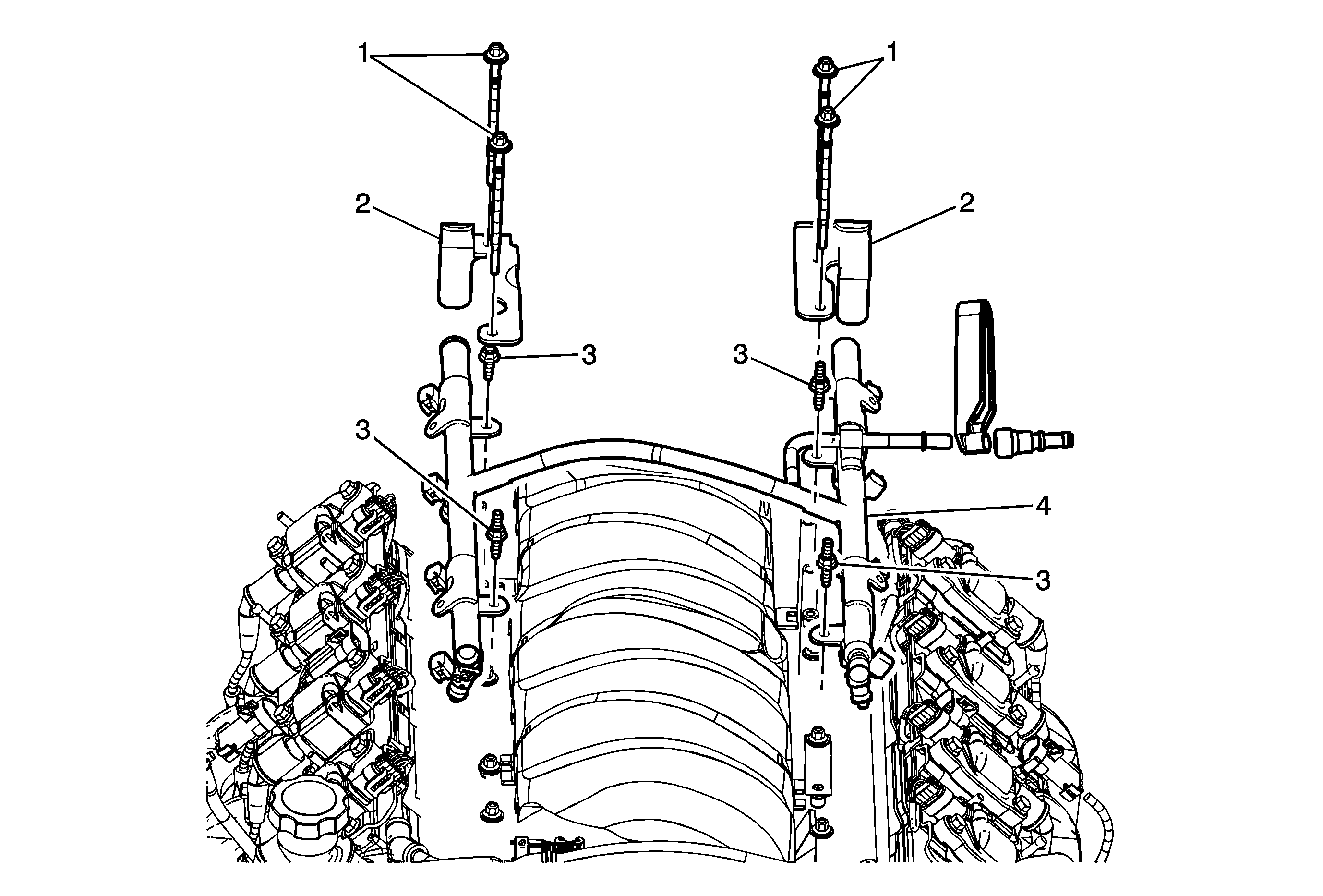
Callout | Component Name |
|---|---|
Preliminary Procedures
| |
1 | Intake Manifold Bolt (Qty: 4) Caution: Refer to Fastener Caution in the Preface section. ProcedureApply a 5 mm (0.20 in) band of GM P/N 12345382 (Canadian P/N 10953489) thread-lock or equivalent to the threads of the fuel rail and intake manifold bolts. Tighten |
2 | Stop Bracket (Qty: 2) Caution: The fuel rail stop bracket must be installed onto the engine assembly. The stop bracket serves as a protective shield for the fuel rail in the event of a vehicle frontal crash. If the fuel rail stop bracket is not installed and the vehicle is involved in a frontal crash, fuel could be sprayed possibly causing a fire and personal injury from burns. |
3 | Fuel Rail Bolt (Qty: 4) Tighten |
4 | Fuel Rail Procedure
Special ToolsJ 37088-A Fuel Line Disconnect Tool Set |
