Cylinder Head Replacement - Right Side 6.2L, LS3, 7.0L, LS7
Special Tools
| • | J 45059 Angle Meter |
| • | J 42385-100 Head/Main Bolt Thread Repair Kit |
Removal Procedure
- Remove the valve rocker arms and pushrods. Refer to Valve Rocker Arm and Push Rod Replacement.
- Remove the engine coolant air bleed pipe and covers. Refer to Coolant Air Bleed Pipe Assembly Replacement.
- Remove the exhaust manifold. Refer to Exhaust Manifold Replacement - Right Side.
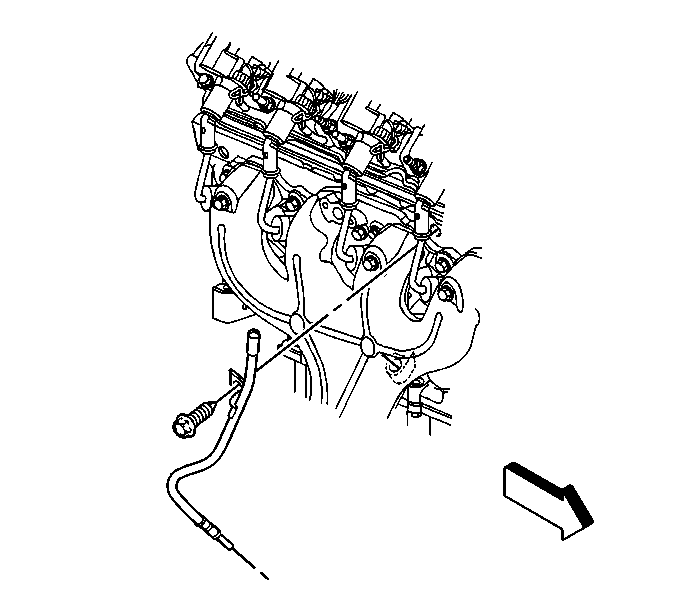
- Remove the oil level indicator tube bolt.
- Reposition the oil level indicator tube, if necessary.
- Remove the intake manifold. Refer to Intake Manifold Replacement.
- Remove the wiring harness from the clip at the rear of the cylinder head.
- Remove the cylinder head bolts.
- Remove the cylinder head.
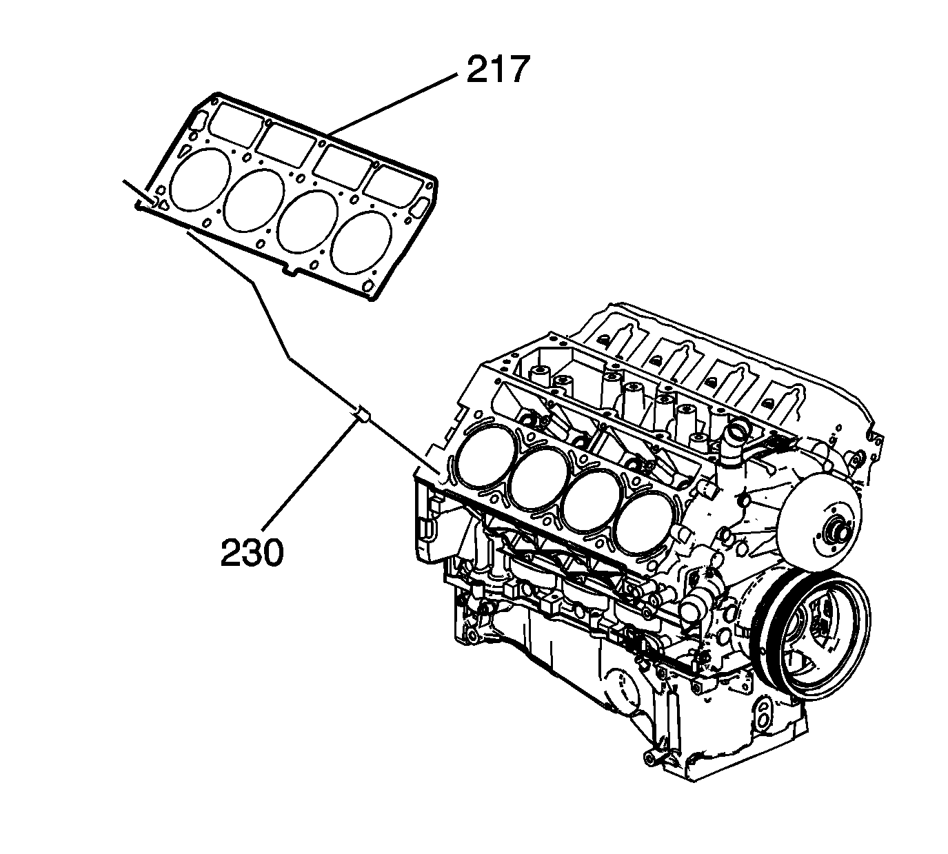
- Remove the cylinder head gasket (217).
- Discard the gasket.
- Discard the cylinder head bolts.
- Clean and inspect the cylinder head. Refer to Cylinder Head Cleaning and Inspection.
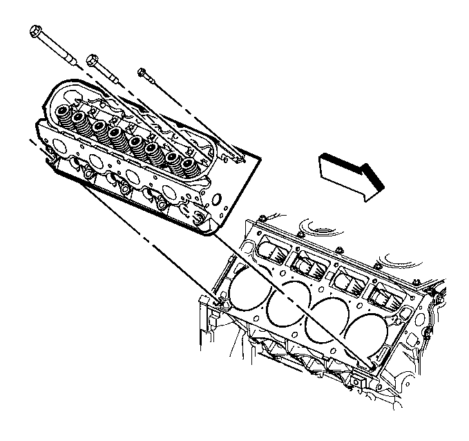
Note: The cylinder head bolts are NOT reusable.
Caution: After removal, place the cylinder head on 2 wood blocks in order to prevent damage to the sealing surfaces.
Installation Procedure
Warning: Wear safety glasses in order to avoid eye damage.
Caution: Clean all dirt, debris, and coolant from the engine block cylinder head bolt holes. Failure to remove all foreign material may result in damaged threads, improperly tightened fasteners or damage to components.
- Clean the engine block cylinder head bolt holes, if required.
- Spray cleaner into the hole. Refer to Adhesives, Fluids, Lubricants, and Sealers for the correct part number.
- Clean the cylinder head bolt holes with compressed air.
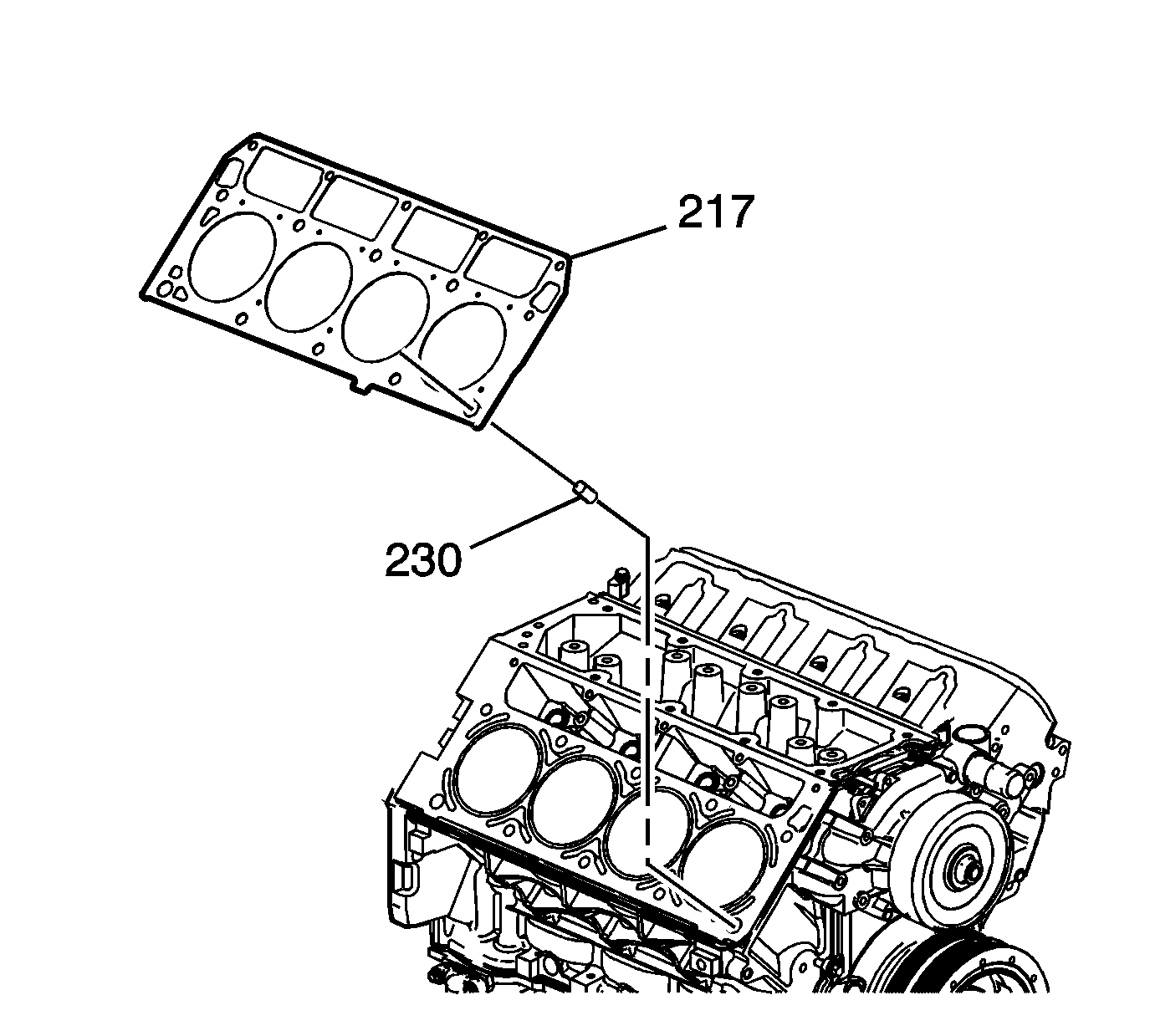
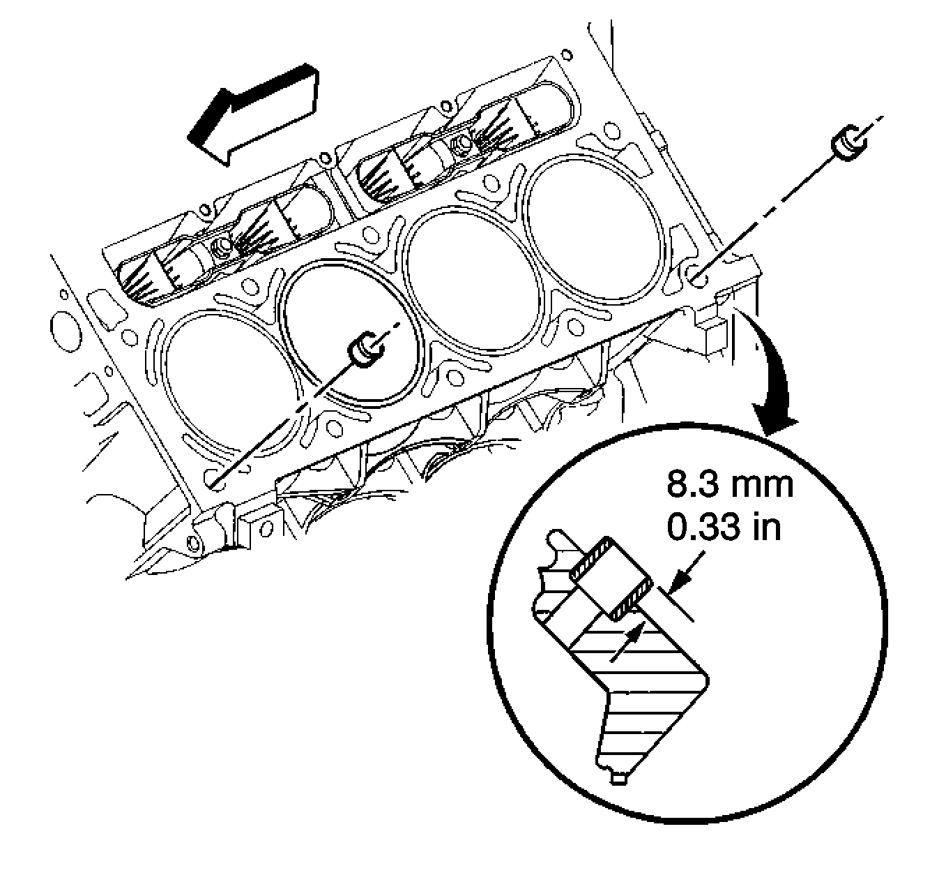
- Install the cylinder head locating pins (230).
- Inspect the locating pins for proper installation.
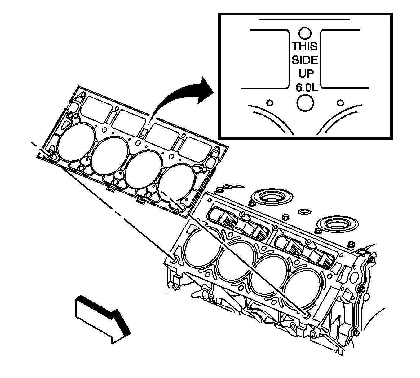
- Inspect the displacement markings on the gasket for proper usage.
- Install the NEW cylinder head gasket (217) onto the locating pins.
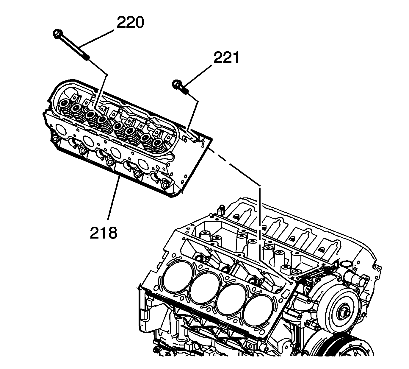
- Install the cylinder head (218) onto the locating pins and the gasket.
- Install the NEW cylinder head bolts (220, 221).
- Tighten the cylinder head bolts.
- Install the wiring harness to the clip at the rear of the cylinder head.
- Install the intake manifold. Refer to Intake Manifold Replacement.
- Position the oil level indicator tube into place.
- Install the oil level indicator tube bolt and tighten to 25 N·m (18 lb ft).
- Install the exhaust manifold. Refer to Exhaust Manifold Replacement - Right Side.
- Install the engine coolant air bleed pipe. Refer to Coolant Air Bleed Pipe Assembly Replacement.
- Install the valve rocker arms and pushrods. Refer to Valve Rocker Arm and Push Rod Replacement.
Note:
• Do not use the cylinder head bolts again. Install NEW cylinder head bolts during assembly. • Do not use any type of sealant on the cylinder head gasket, unless specified. • The cylinder head gaskets (217) must be installed in the proper direction and position.
Thread repair tool J 42385-107 may be used to clean the threads of old threadlocking material.

Caution: Refer to Fastener Caution in the Preface section.
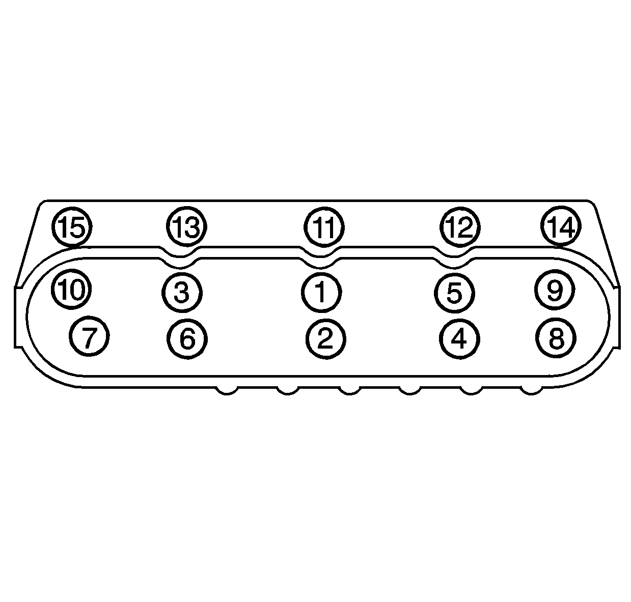
| 10.1. | Tighten the M11 cylinder head bolts (1-10) a first pass in sequence to 30 N·m (22 lb ft). |
| 10.2. | Tighten the M11 cylinder head bolts (1-10) a second pass in sequence to 90 degrees using the J 45059 . |
| 10.3. | Tighten the M11 cylinder head bolts (1-10) a final pass in sequence to 70 degrees using the J 45059 . |
| 10.4. | Tighten the M8 cylinder head bolts (11-15) to 30 N·m (22 lb ft). Begin with the center bolt (11) and alternating side-to-side, work outward tightening all of the bolts. |

Cylinder Head Replacement - Right Side LS9
Special Tools
| • | J 37088-A Fuel Line Disconnect Tool Set |
| • | J 45059 Angle Meter |
| • | For equivalent regional tools, refer to Special Tools |
Removal Procedure
- Open and remove the hood.
- Disconnect the negative battery cable.
- Raise the vehicle. Refer to Lifting and Jacking the Vehicle.
- Drain the engine cooling system at the right front of the vehicle.
- Drain the intercooler cooling system at the left front of the vehicle.
- Lower the vehicle.
- Remove the engine sight shield.
- Disconnect the mass airflow (MAF) sensor electrical connector located at the air inlet duct.
- Disconnect the positive crankcase ventilation (PCV) fresh air tube from the air inlet duct.
- Remove the air inlet duct.
- Disconnect the throttle actuator electrical connectors from the throttle body.
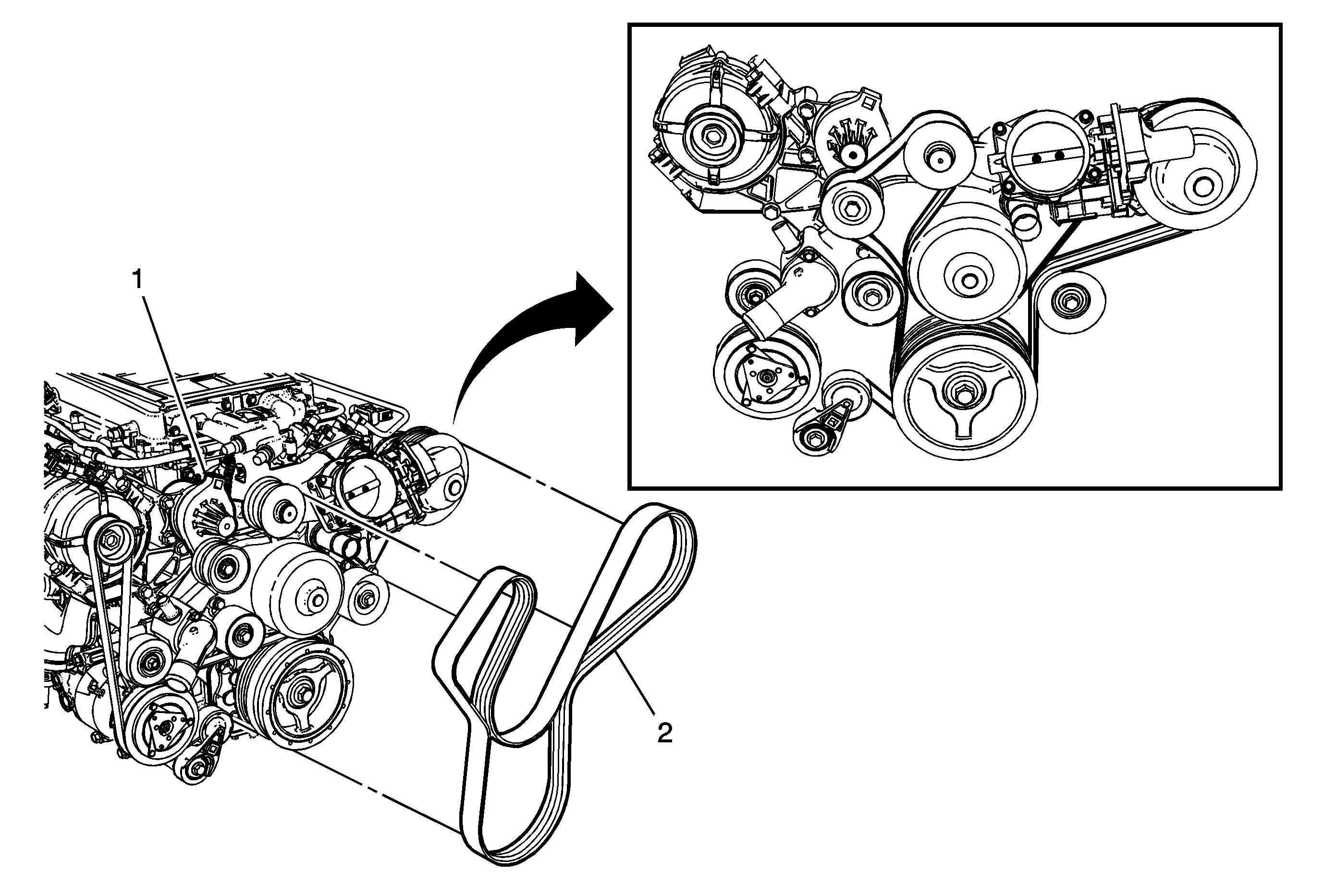
- Remove the supercharger and accessory drive belts.
- Disconnect the intercooler cooling system hoses.
- Disconnect the generator electrical connector and battery positive cable.
- Remove the generator.
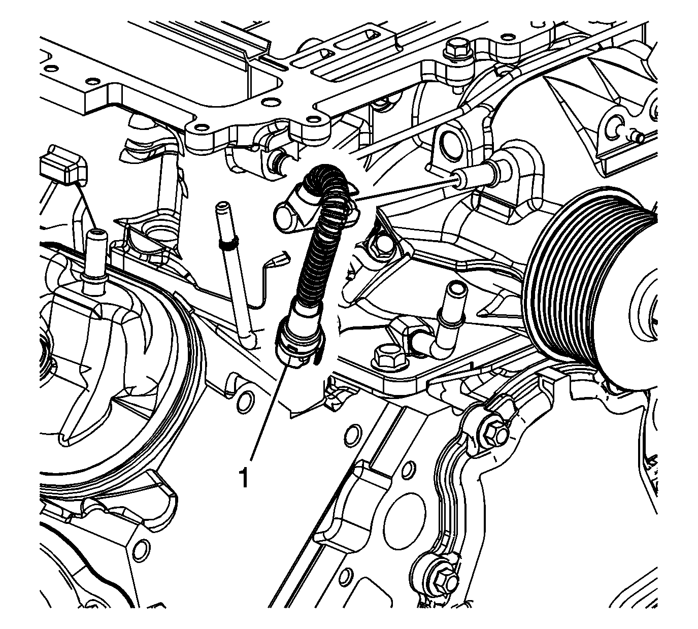
- Remove the supercharger belt tensioner (1) and bolts.
- Disconnect the purge solenoid electrical connector at the left front of the supercharger.
- Remove the purge tube from the purge solenoid.
- Disconnect the electrical connector from the supercharger actuator solenoid.
- Disconnect the active exhaust vacuum hose from the front of the supercharger assembly.
- Disconnect the fuel injector and ignition coil harness connector.
- Disconnect the air outlet pressure sensor harness connector from the sensor and separate the harness from the fuel rail bracket and reposition at the left side of the intercooler.
- Disconnect the inlet air temperature sensor electrical connector from the sensor at the right side of the intercooler.
- Disconnect the fuel injector and ignition coil harness connector.
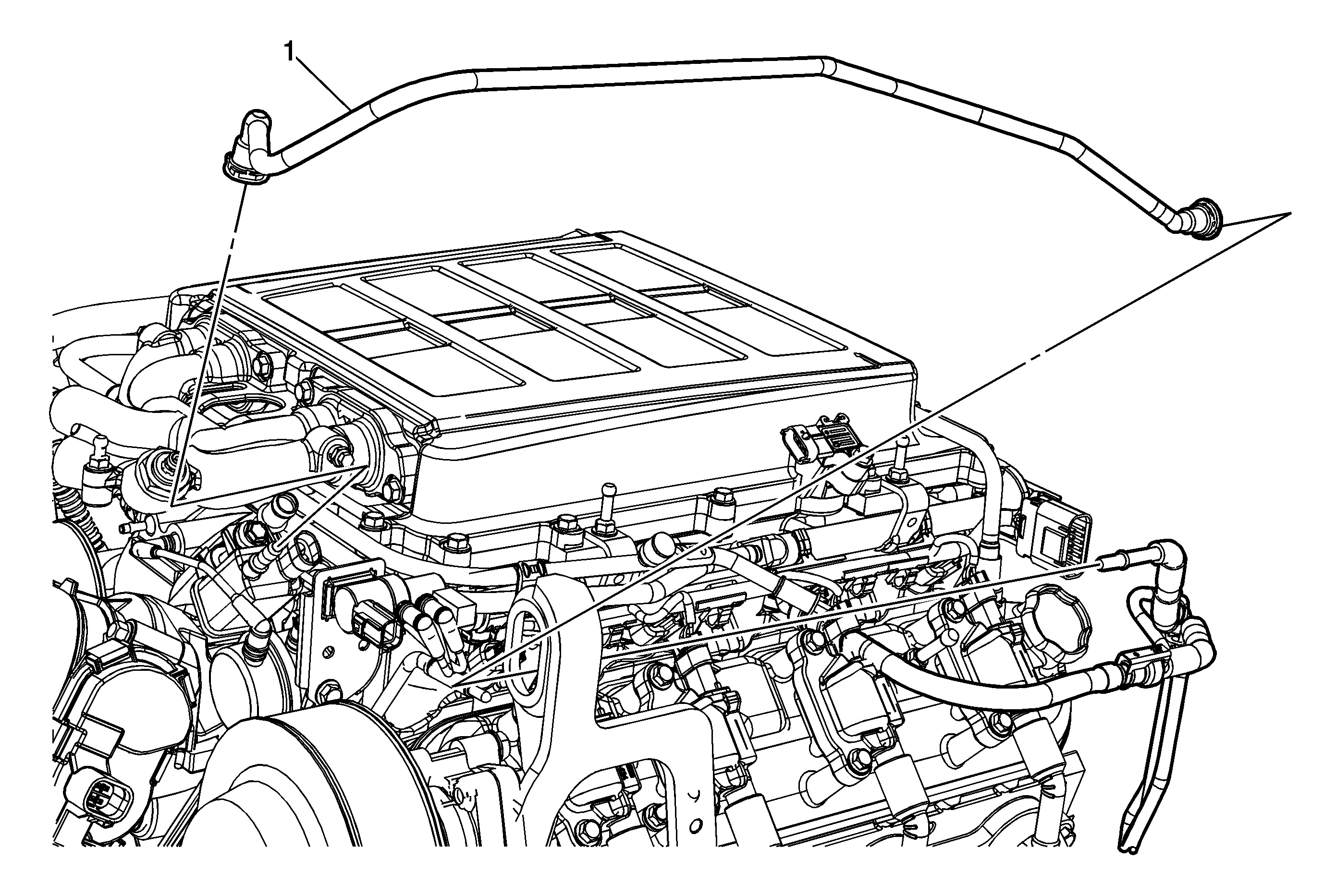
- Disconnect and remove the PCV fresh air hose assembly from the right and left valve covers and dry sump oil tank.
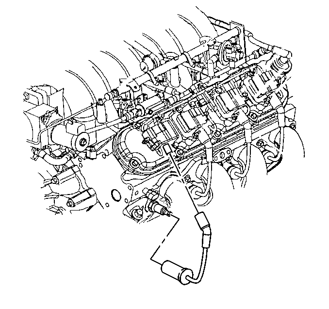
- Disconnect the ignition coil electrical connectors from the ignition coils.
- Remove the rear hood seal from the cowl.
- Raise the vehicle and remove the sway bar bushing-to-cradle brackets and bolts, left and right side.
- Loosen the cradle bolts and lower the engine assembly and cradle assembly approximately 1 inch.
- Lower the vehicle.
- Remove the intercooler cover and bolts.
- Place the supercharger rotor cover over the exposed areas of the rotors to avoid entry of dirt and debris.
- Remove the PCV dirty air hose from the supercharger.
- Disconnect the fuel system to fuel feed-to-rail hose using the J 37088-A disconnect tool.
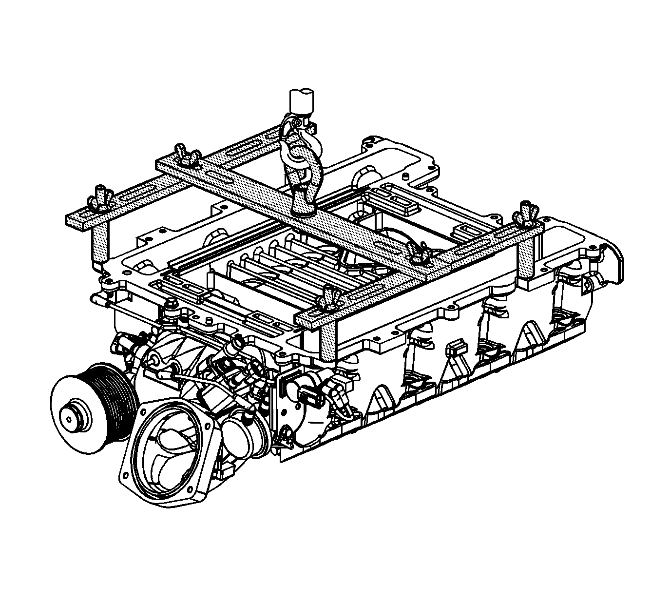
- Remove the supercharger bolts.
- Remove the supercharger assembly.
- Disconnect the spark plug wires from the spark plugs.
- Remove the rear ignition coil from the rocker cover.
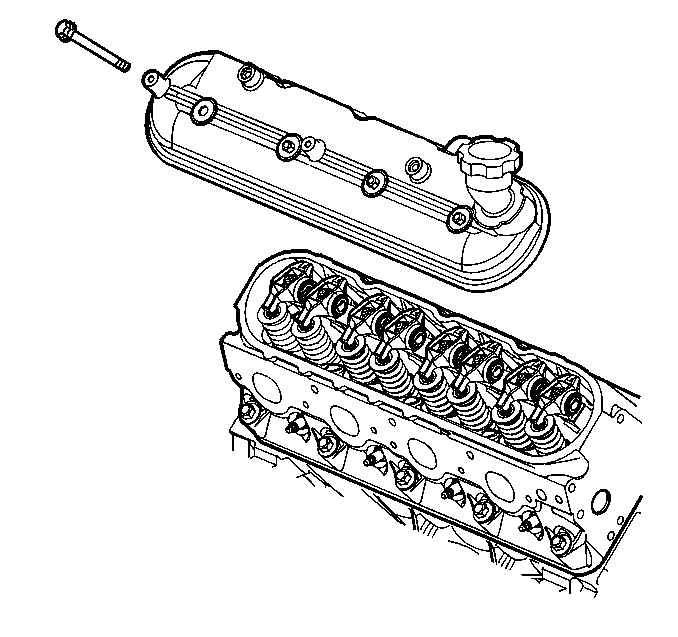
- Remove the rocker cover.
- Loosen the valve rocker arm bolts and lift the rocker arms, pedestal and bolt assembly from the right cylinder head. Discard the rocker arms and bolts and retain the pedestal.
- Remove and discard the pushrods.
- Remove the spark plugs.
- Raise the vehicle.
- Loosen the exhaust takedown pipe-to intermediate pipe joints to allow the exhaust manifold to move away from the cylinder heads.
- Lower the vehicle.
- Remove the exhaust manifold-to-cylinder head bolts.
- Remove and discard the exhaust manifold-to-cylinder head gasket.
- Remove the engine wire harness retaining bolt.
- Remove the coolant air bleed pipes and bolts and reposition the coolant tubes toward the front of engine.
- Remove the coolant plug from the right cylinder head.
- Lift the cylinder head assembly with the generator bracket from the right side of the engine and remove the generator bracket.
- Remove and discard the cylinder head gasket.
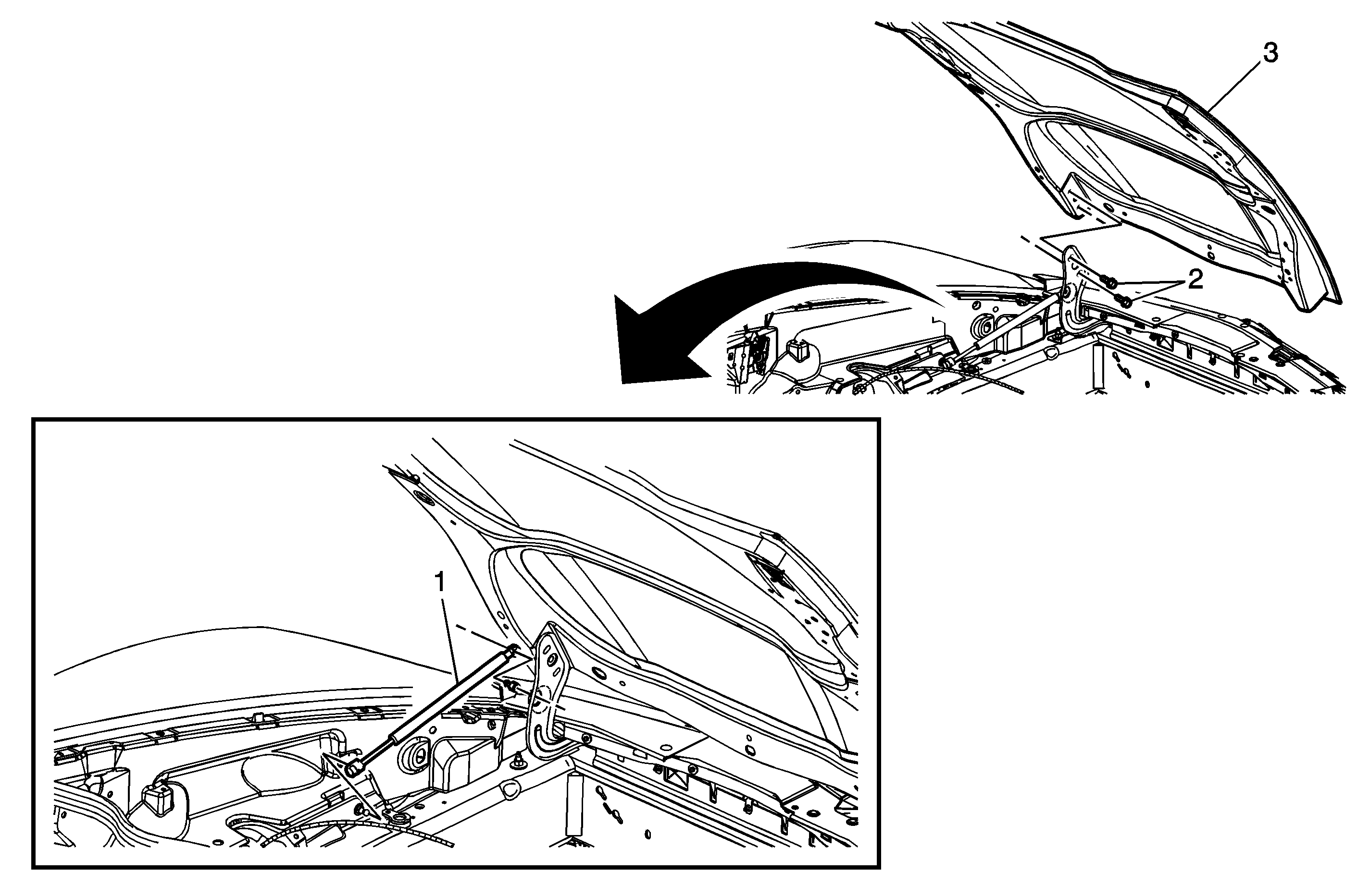
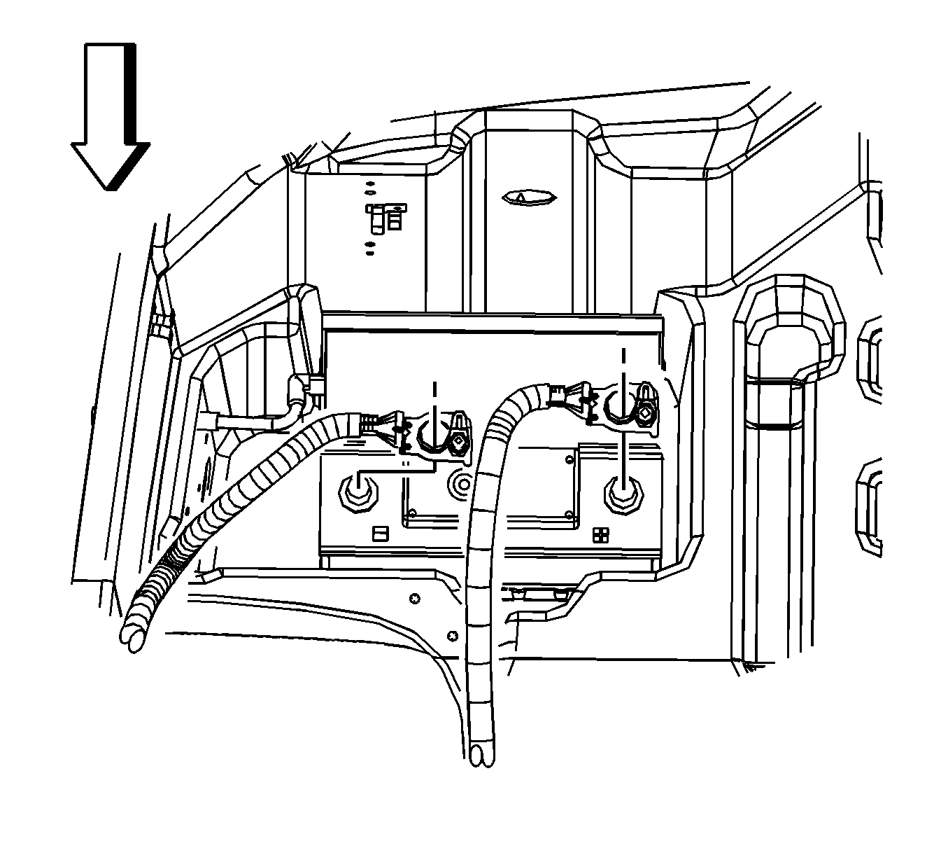
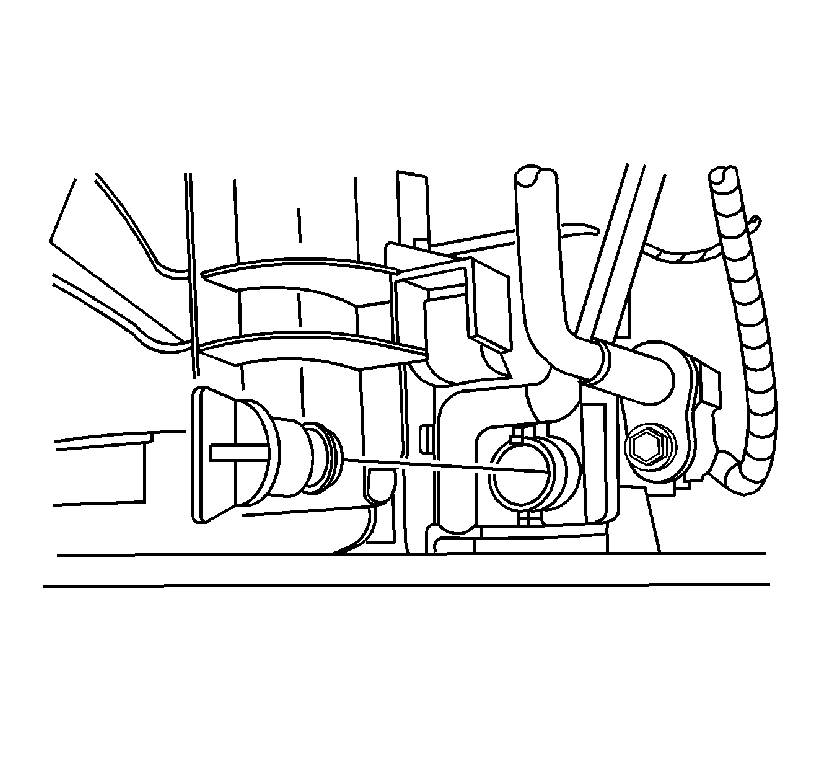
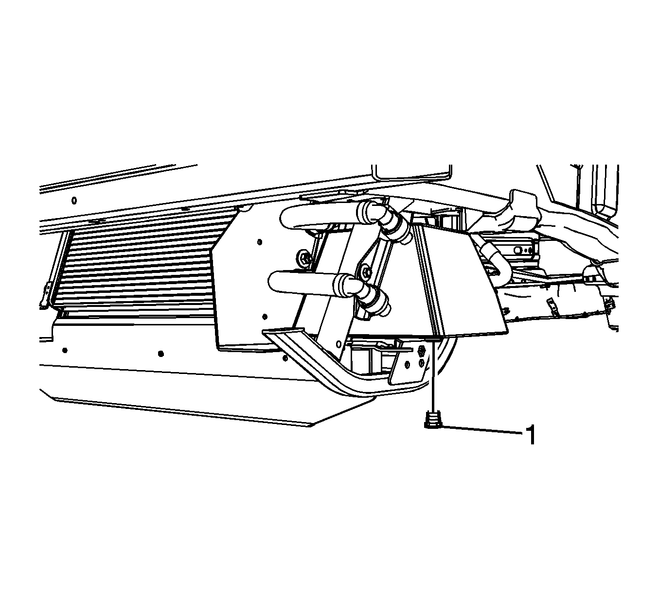
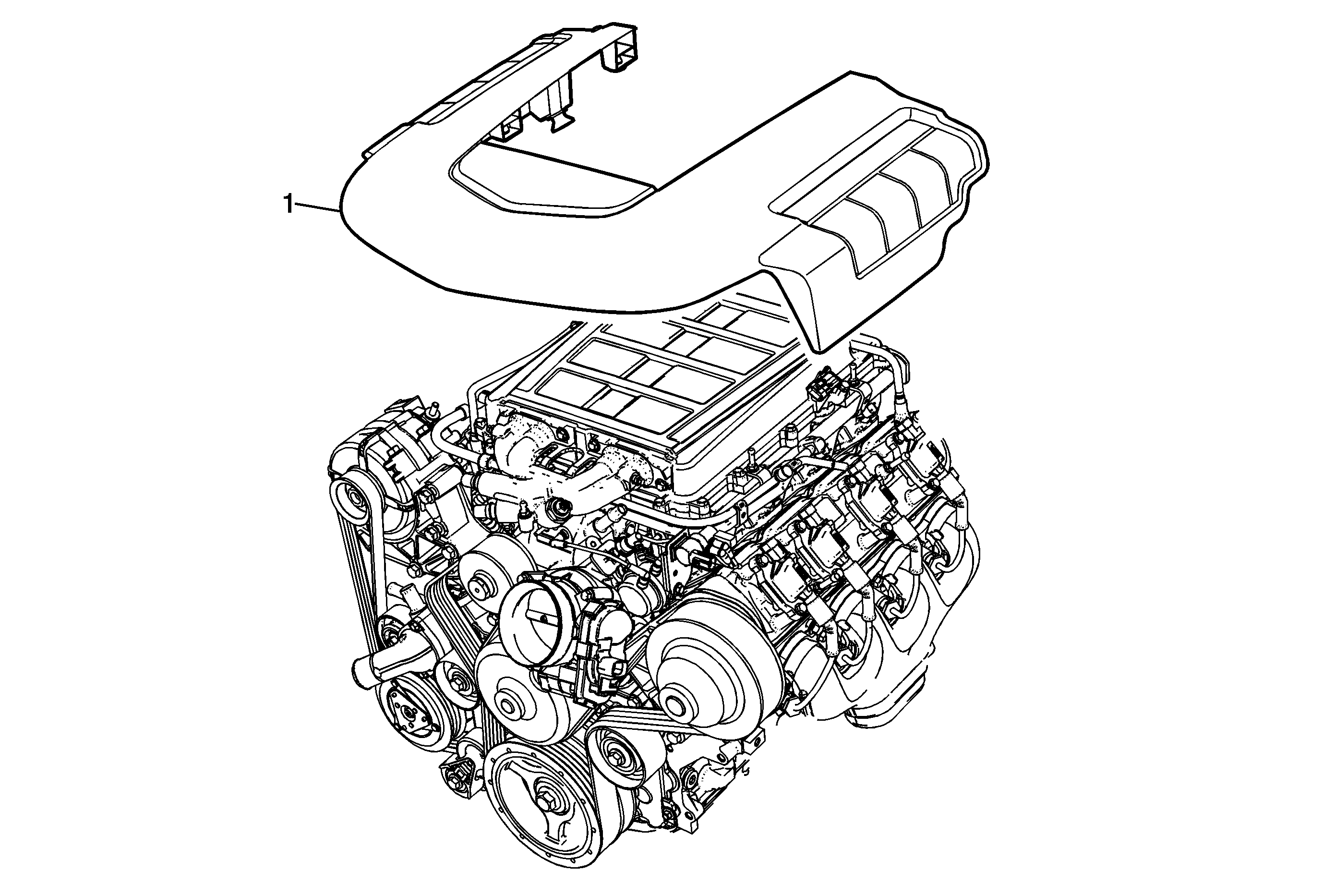
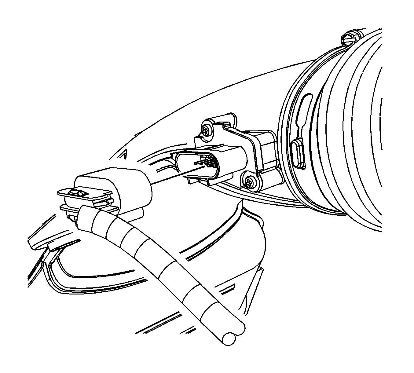
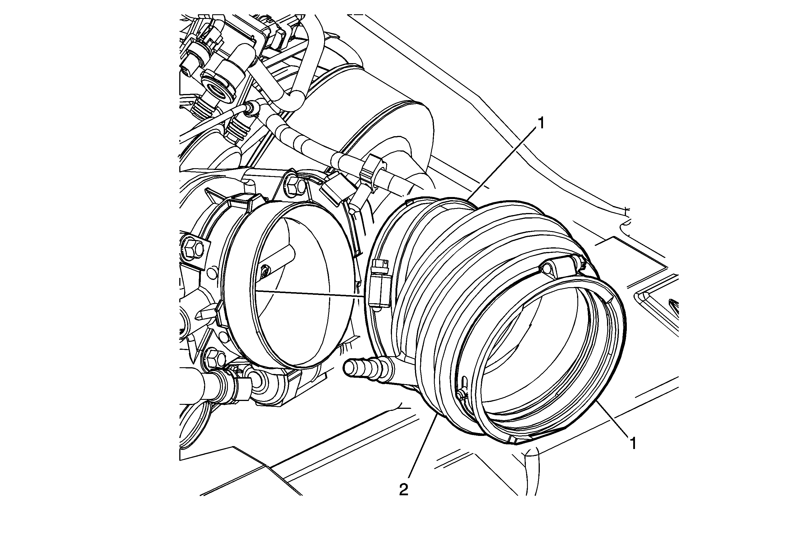
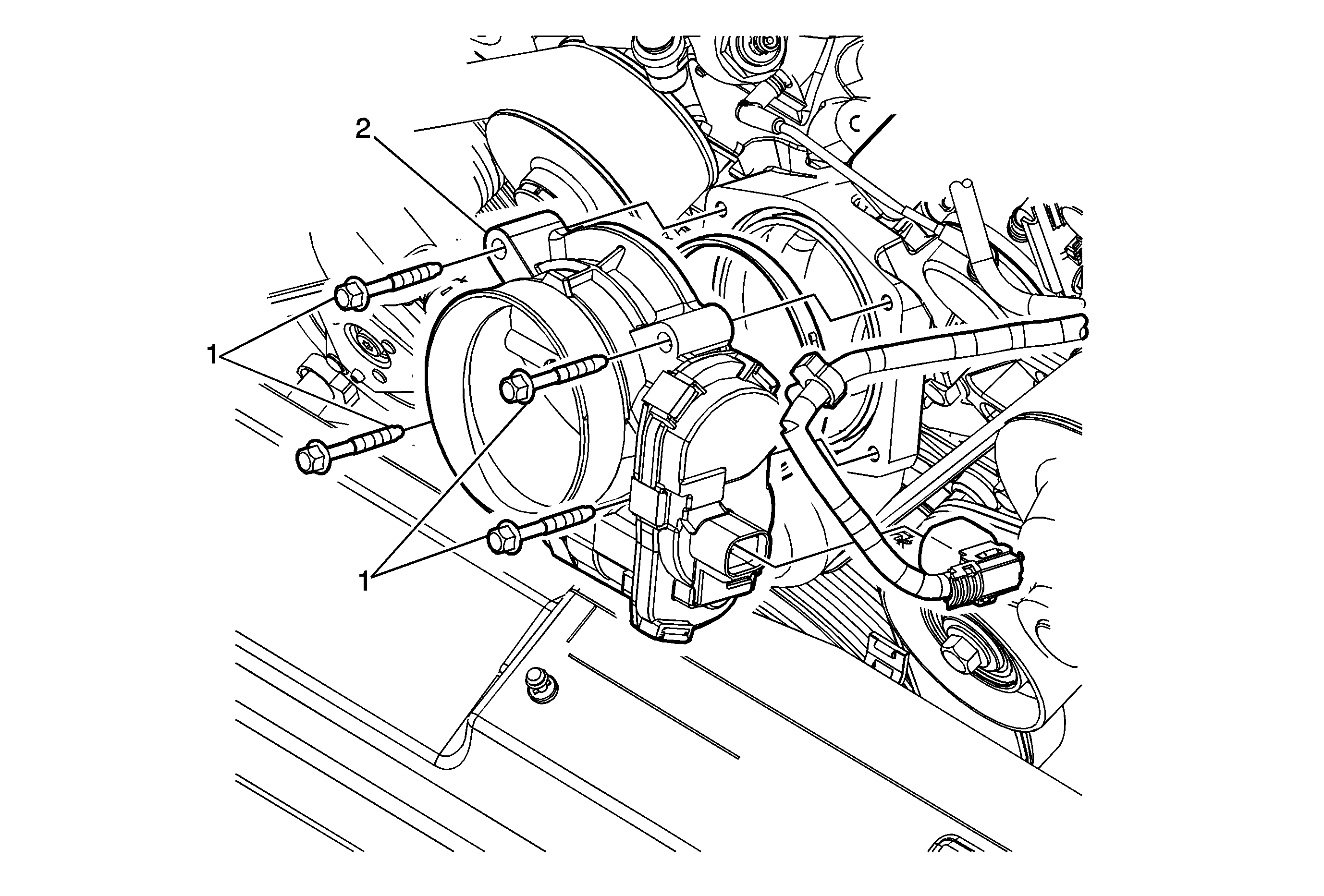
Note: Do not remove throttle body as in above view.
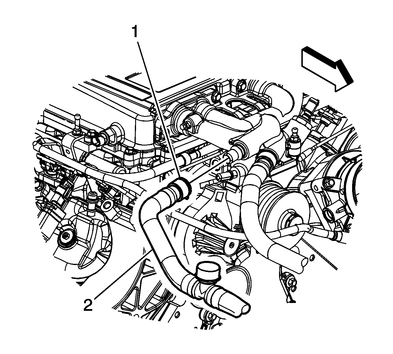
The two large coolant hoses at the front of the intercooler are retained by quick connects.
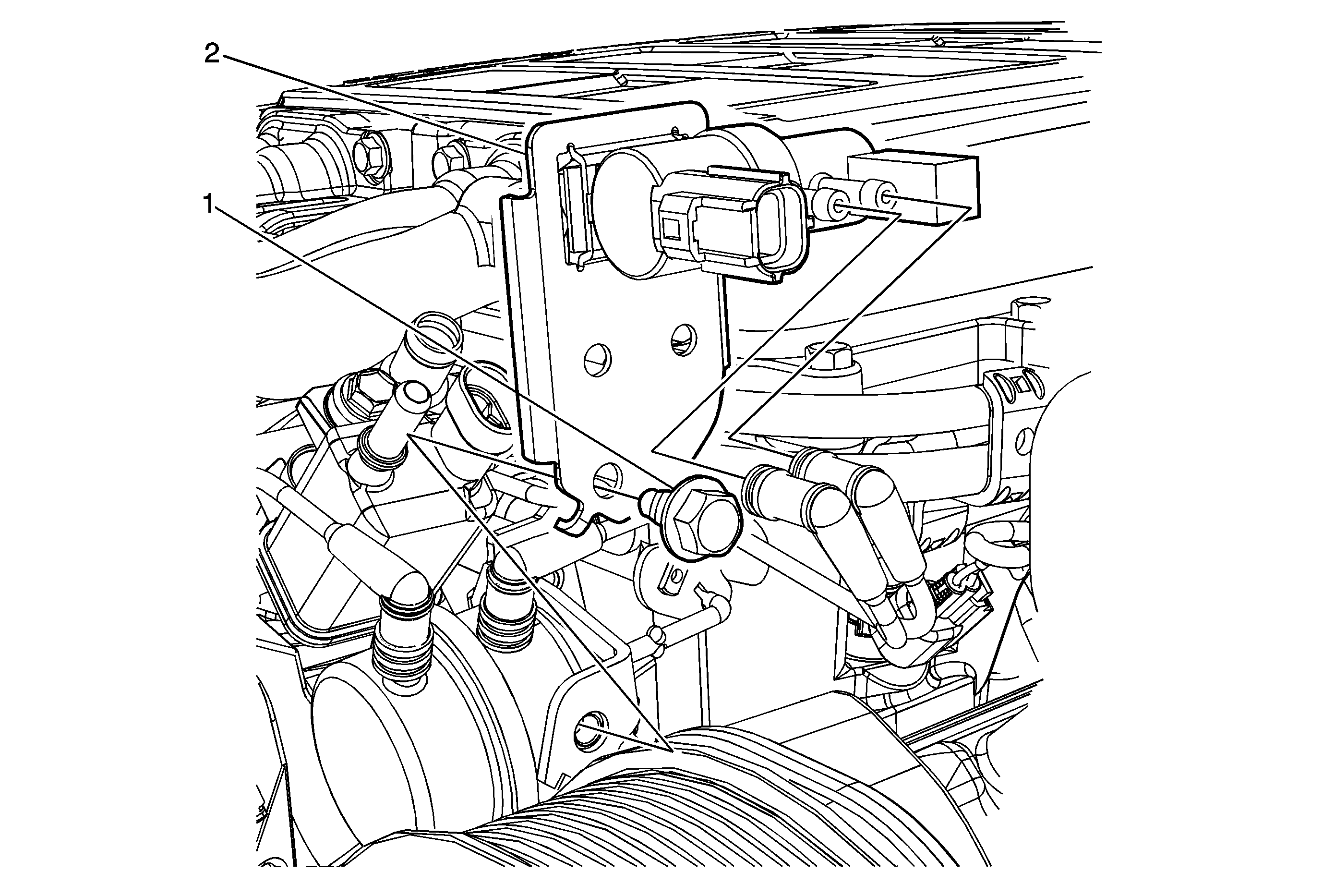
Note: Do not remove the solenoid as in the above view.
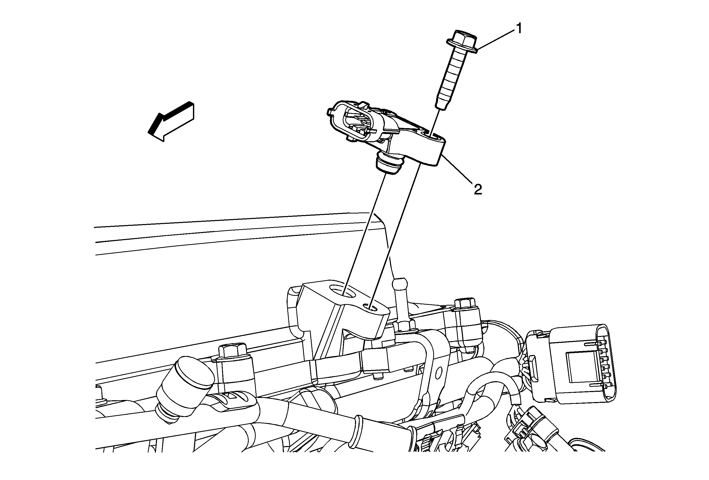
Do not remove the sensor from the intercooler.
Do not remove the sensor from the intercooler.
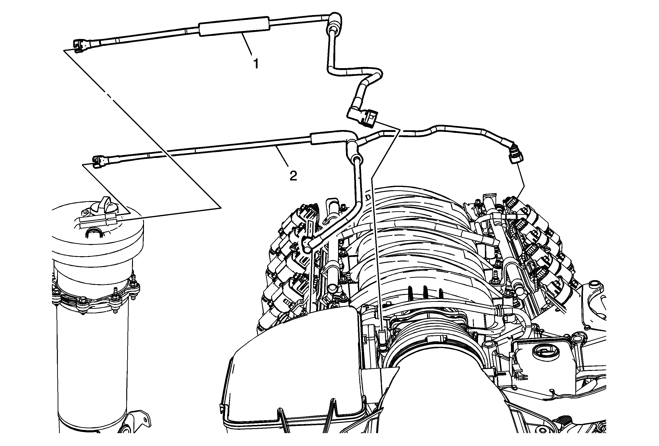
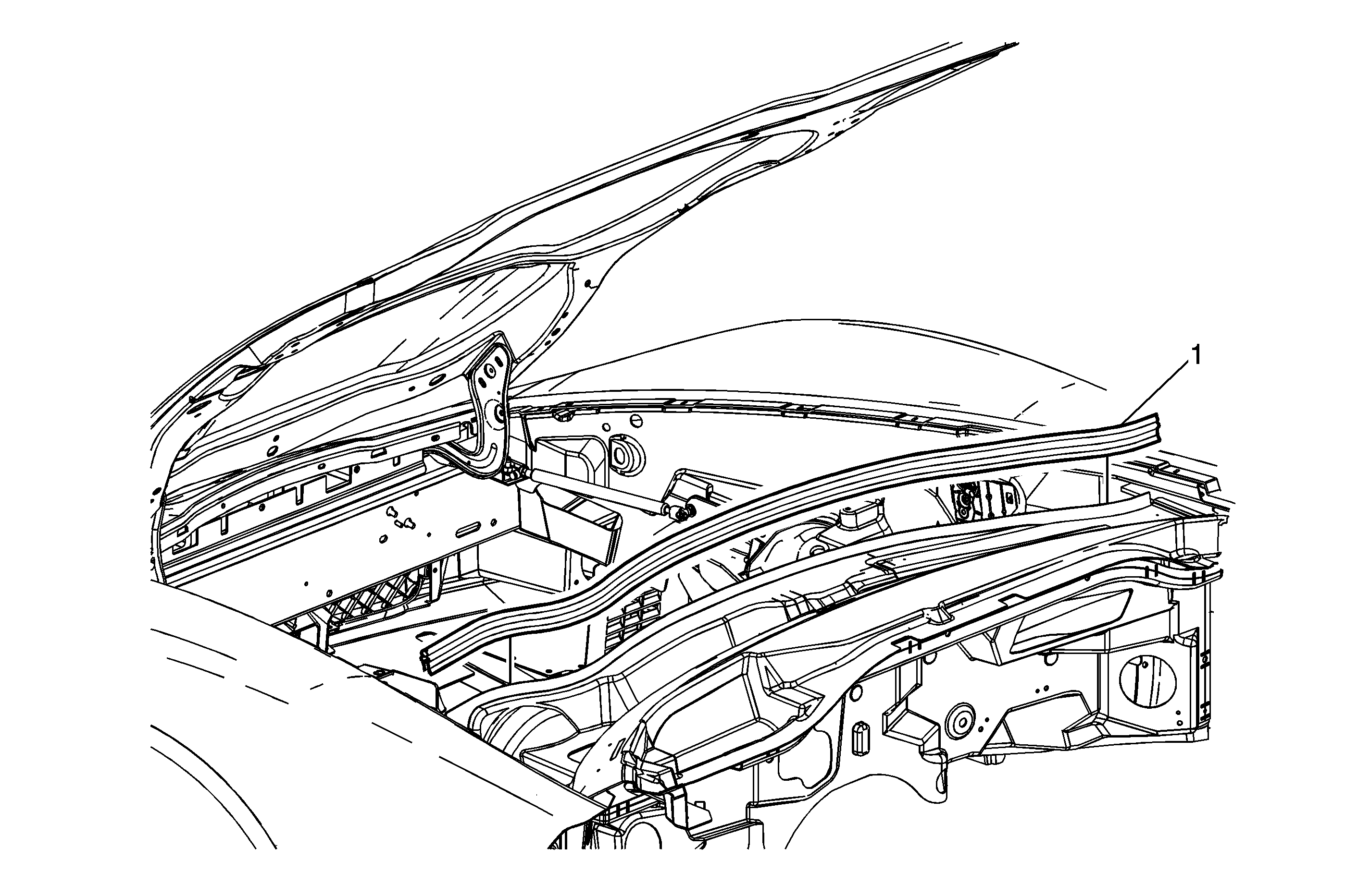
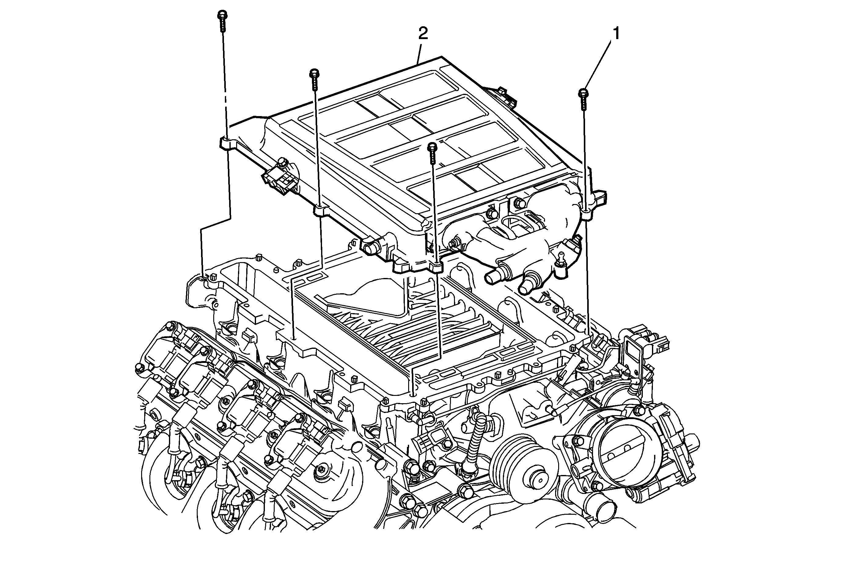
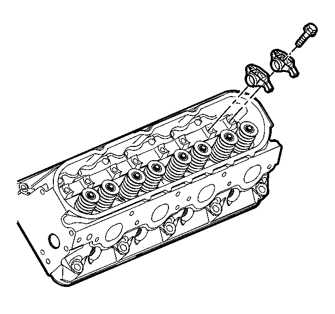
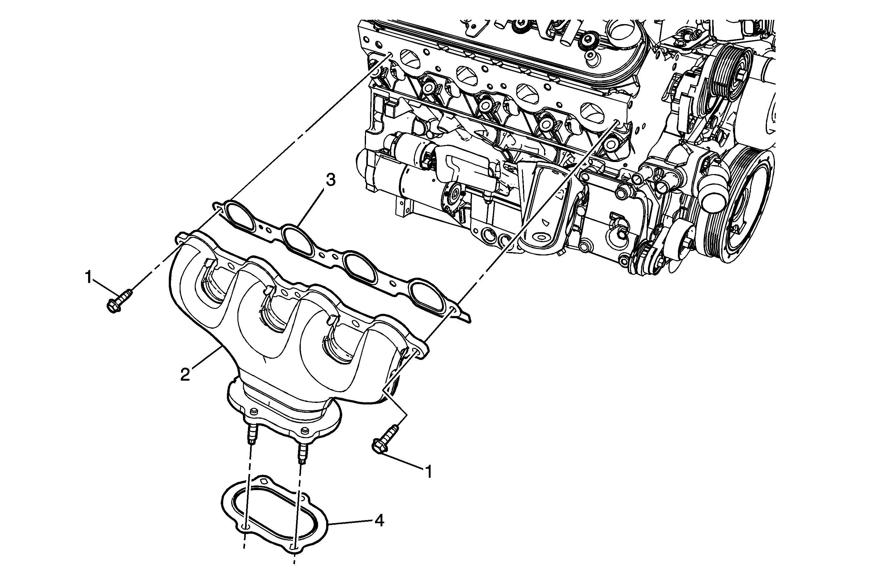
Reposition the exhaust manifold away from the right cylinder head. Discard the bolts.
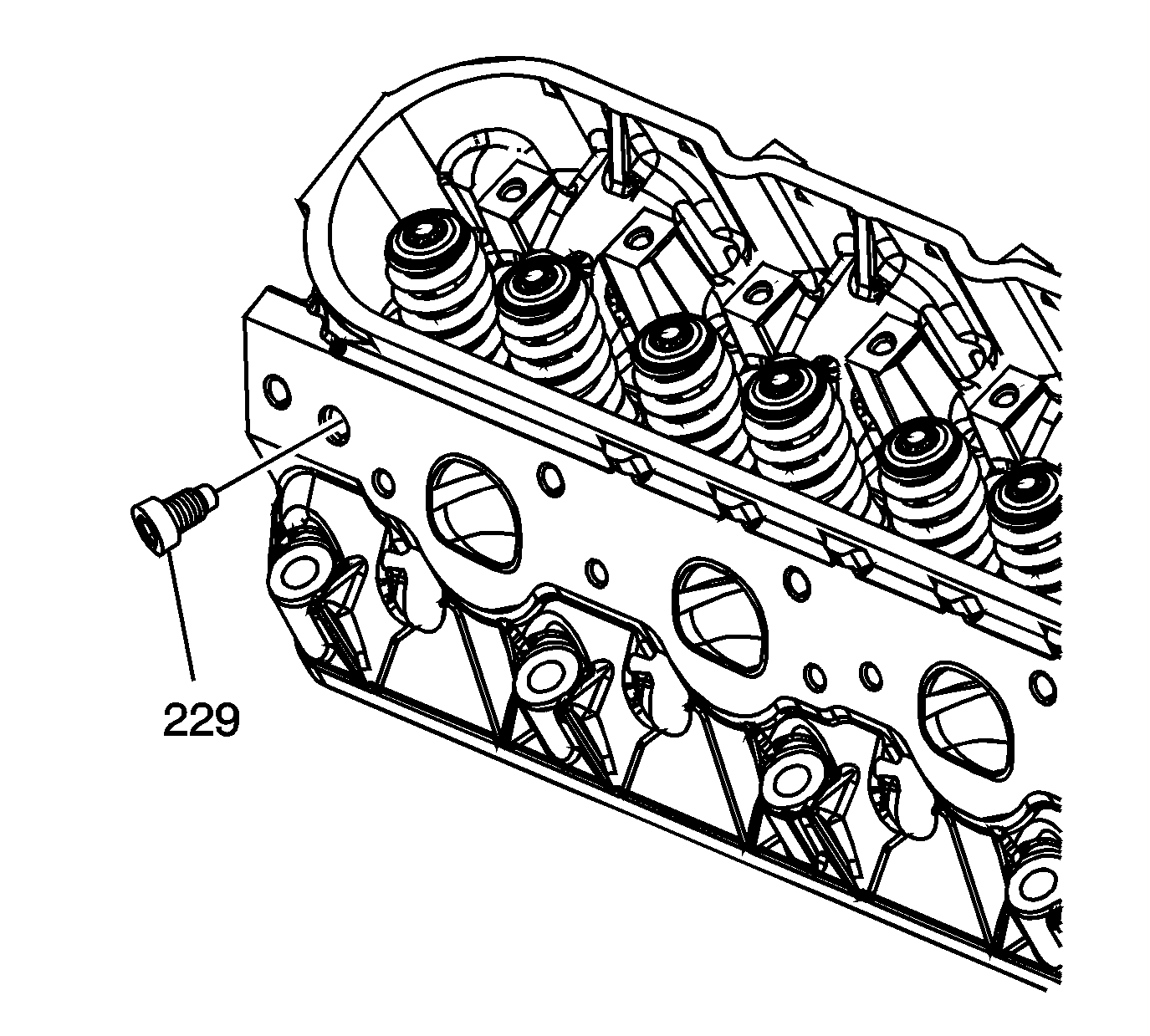
Note: During the installation of the cylinder head plug and temperature sensor, reapply sealant GM P/N 12346004 to the threads before installing.
Note: Use care when handling the used cylinder head to avoid scratching or damaging the sealing surface. Cover the head in bubble wrap type material to avoid damaging the sealing surfaces.
Installation Procedure
- Clean the engine block cylinder head bolt holes, if required.
- Spray cleaner GM P/N 12346139 (Canadian P/N 10953463), GM P/N 12377981 (Canadian P/N 10953463), or equivalent, into the hole.
- Clean the cylinder head bolt holes with compressed air.
- Install the cylinder head locating pins (230).
- Inspect the locating pins for proper installation.
- Inspect the displacement markings on the gasket for proper usage.
- Install the NEW cylinder head gasket (217) onto the locating pins. Install the gasket with the "FRONT" markings at front of engine.
- Install the cylinder head (218) onto the locating pins and the gasket.
- Lubricate the threads of the bolts with clean engine oil.
- Install the NEW cylinder head bolts (220, 221).
- Tighten the cylinder head bolts:
Warning: Refer to Safety Glasses Warning in the Preface section.

Caution: Clean all dirt, debris, and coolant from the engine block cylinder head bolt holes. Failure to remove all foreign material may result in damaged threads, improperly tightened fasteners or damage to components.
Note:
• Do not use the cylinder head bolts again. Install NEW cylinder head bolts during assembly. • Do not use any type of sealant on the cylinder head gasket, unless specified. • The cylinder head gaskets must be installed in the proper direction and position.


Caution: Refer to Fastener Caution in the Preface section.

| 11.1. | Tighten the M12 cylinder head bolts (1-10) a first pass in sequence to 20 N·m (15 lb ft). |
| 11.2. | Tighten the M12 cylinder head bolts (1-10) a second pass in sequence to 80 N·m (60 lb ft). |
| 11.3. | Tighten the M12 cylinder head bolts (1-10) a third pass in sequence to 90 degrees using the J 45059 meter . |
| 11.4. | Tighten the M12 cylinder head bolts (1-10) a final pass in sequence to 45 degrees using the J 45059 meter . |
| 11.5. | Tighten the M8 cylinder head bolts (11-15) to 30 N·m (22 lb ft). Begin with the center bolt (11) and alternating side-to-side, work outward tightening all of the bolts. |
