Engine Front Cover Replacement 6.2Land 7.0L
Special Tools
EN-48853 Front Cover Alignment Tool
Removal Procedure
- Remove the accessory drive belt. Refer to Drive Belt Replacement - Accessory.
- Remove the crankshaft balancer. Refer to Crankshaft Balancer Replacement.
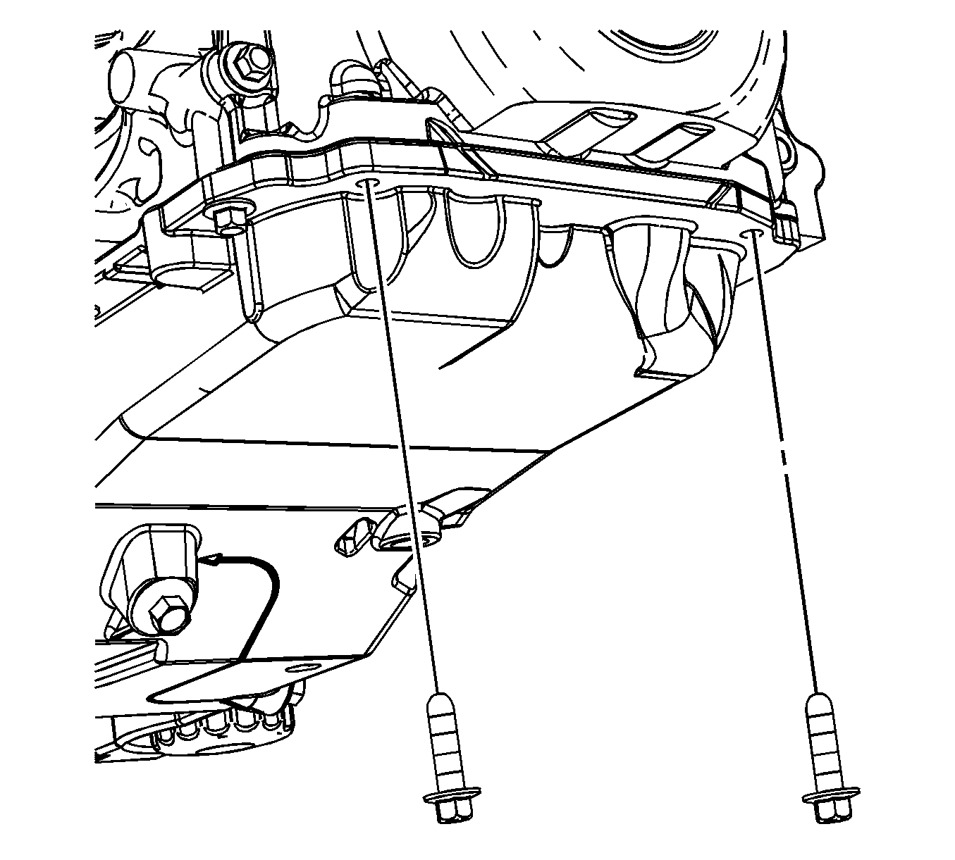
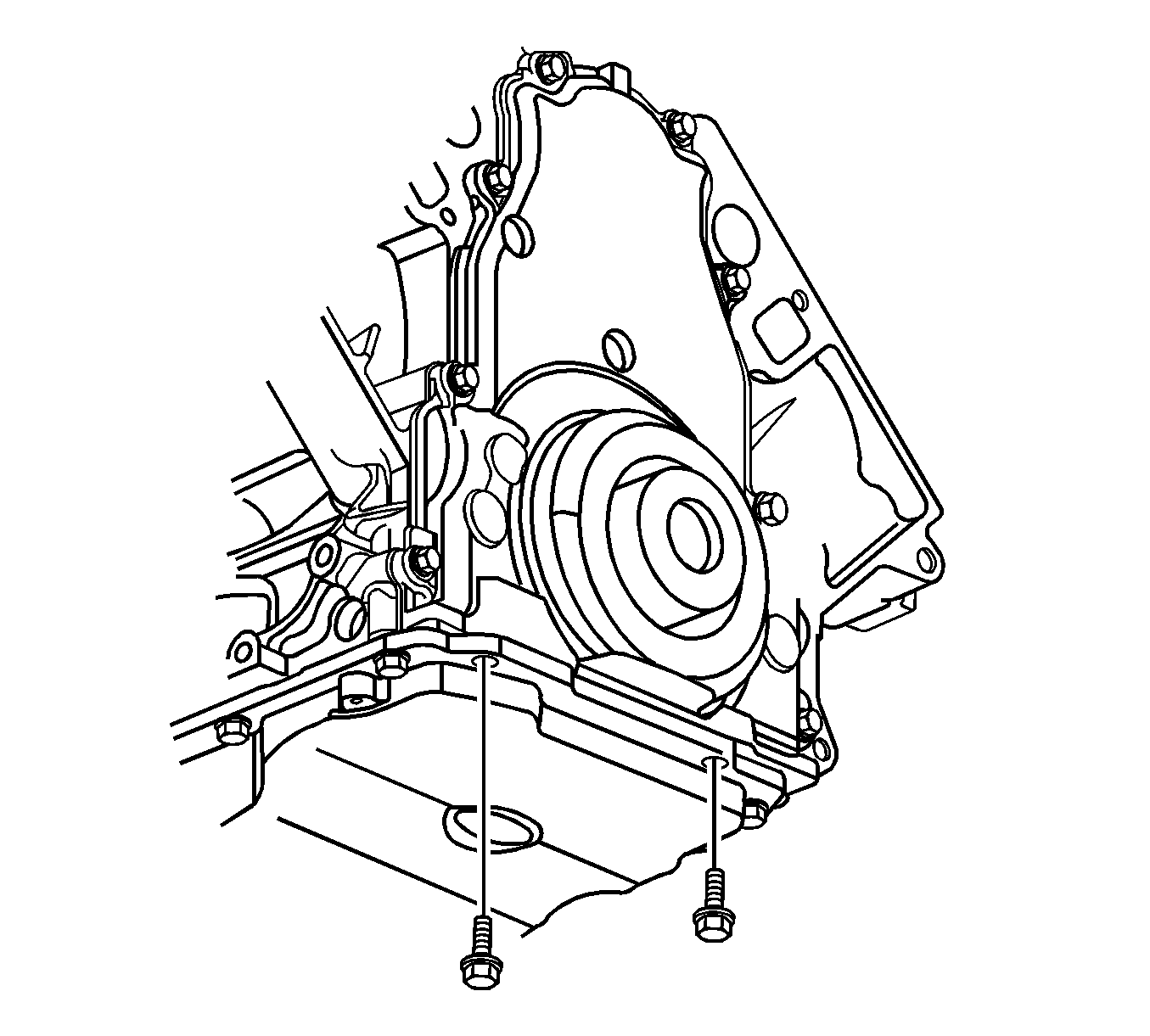
- Remove the 2 front oil pan to front cover M8 bolts.
- Remove the water pump. Refer to Water Pump Replacement.
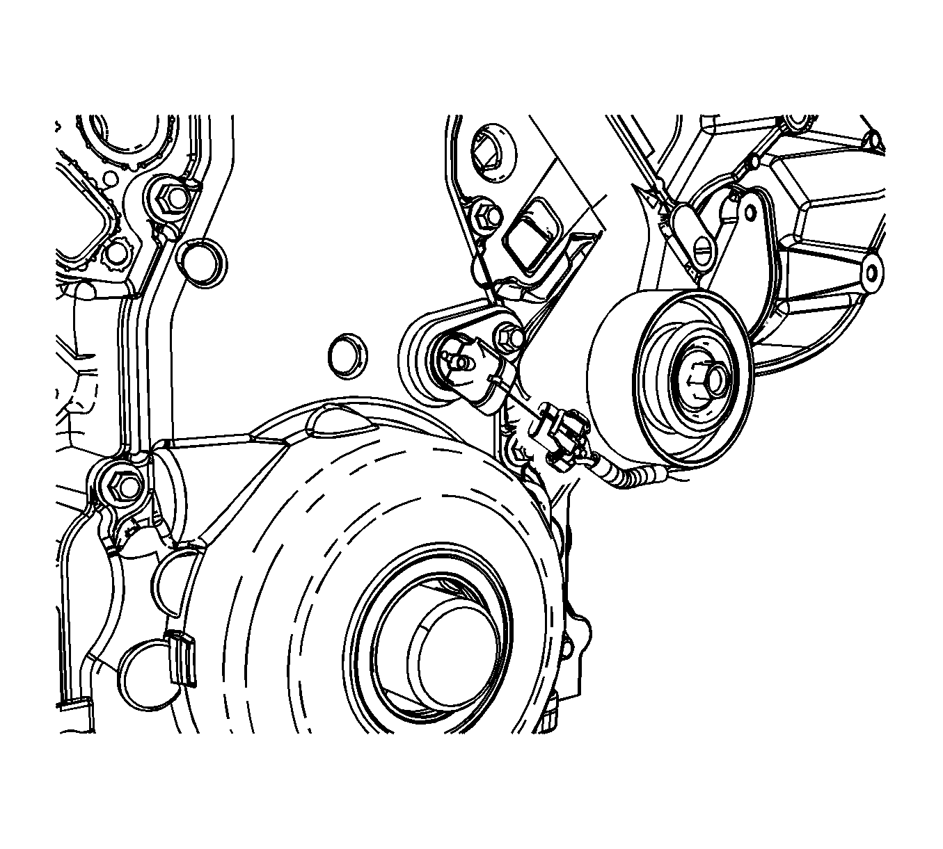
- Disconnect the camshaft position (CMP) sensor electrical connector.
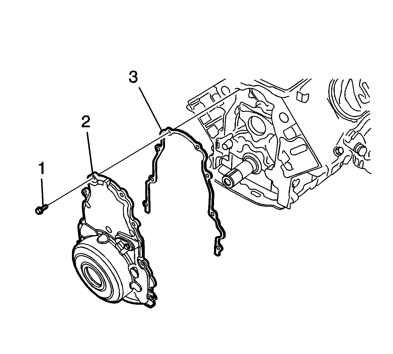
- Remove the front cover bolts (1).
- Remove the front cover (2) and gasket (3).
- Discard the front cover gasket.
- Clean and inspect the engine front cover. Refer to Engine Front Cover Cleaning and Inspection.
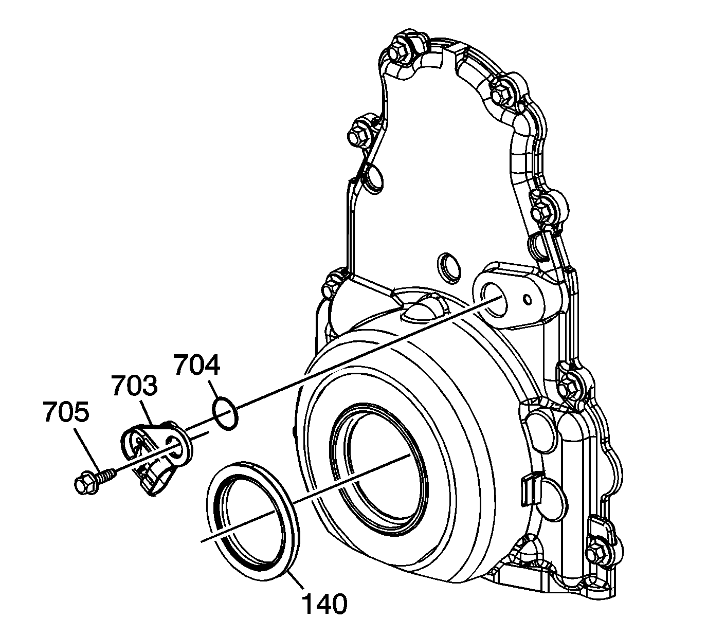
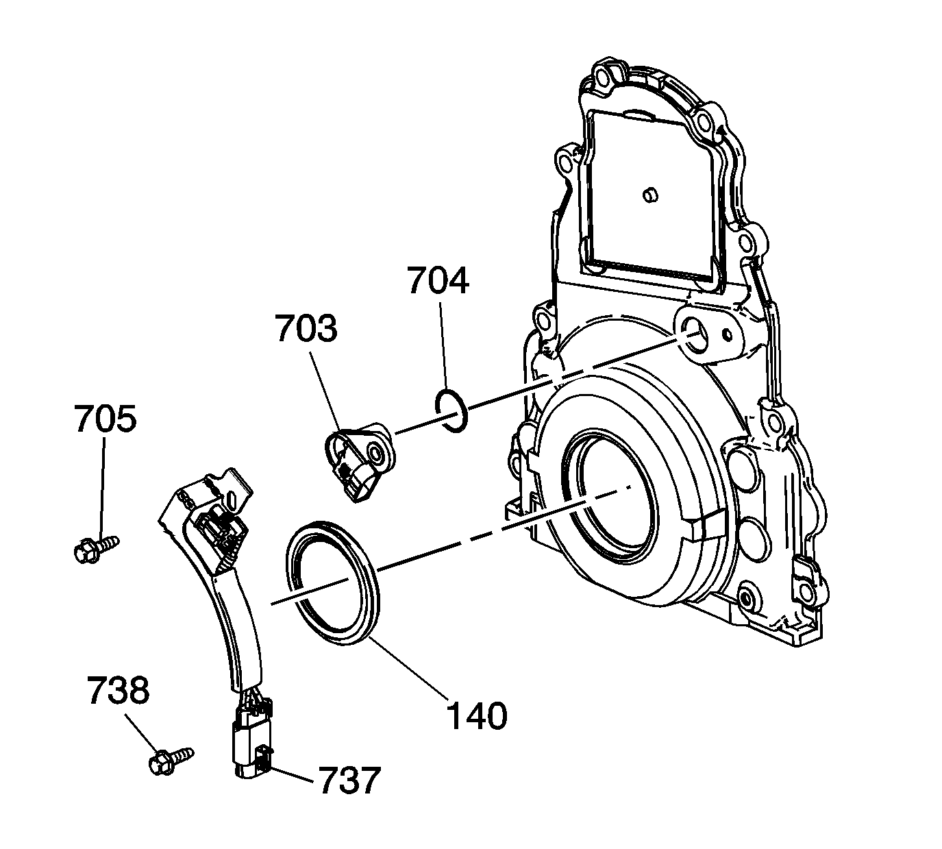
- Remove the oil seal (140).
- Remove the bolt (705), camshaft position (CMP) sensor (703).
- Remove the O-ring (704) from the sensor, as required.
Installation Procedure
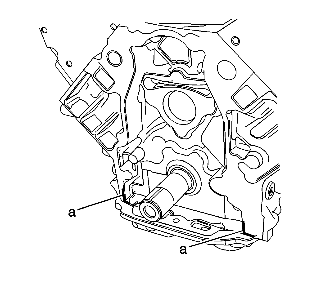
- Apply a 5 mm (0.2 in) bead of sealant 20 mm (0.8 in) long to the engine block. Apply the sealant to the T joint location where the oil pan meets the front of the engine block. Refer to Adhesives, Fluids, Lubricants, and Sealers for the correct part number.
- Install a NEW crankshaft front oil seal. Refer to Crankshaft Front Oil Seal Replacement.
- Install the front cover gasket (3), front cover (2), and bolts (1).
- Tighten the cover bolts finger tight. Do not overtighten. Tighten the tool-to-engine block bolts to 25 N·m (18 lb ft).
- Install the EN-48853 onto the crankshaft.
- Tighten the crankshaft balancer bolt by hand until snug. Do not overtighten.
- Install the front cover.
- Remove the tool.
- Inspect the CMP sensor O-ring seal (704) for cuts or damage. If the seal is not cut or damaged, it may be used again.
- Lubricate the O-ring seal with clean engine oil.
- Install the O-ring seal onto the sensor (703).
- Install the sensor to the cover.
- Install the CMP sensor and bolt (705) and tighten to 12 N·m (106 lb in).
- Install the new crankshaft front oil seal. Refer to Crankshaft Front Oil Seal Replacement.
- Connect the CMP sensor electrical connector.
- Install the water pump. Refer to Water Pump Replacement.
- Install the crankshaft balancer. Refer to Crankshaft Balancer Replacement.
- Install the accessory drive belt. Refer to Drive Belt Replacement - Accessory.

Note:
• Do not use the crankshaft oil seal or the engine front cover gasket again. • Do not apply any type of sealant to the front cover gasket, unless specified. • The special tools in this procedure are used to properly align the engine front cover at the oil pan surface and to center the crankshaft front oil seal. - All gasket surfaces should be free of oil or other foreign material during assembly. - The crankshaft front oil seal MUST be centered in relation to the crankshaft. - The oil pan sealing surface at the front cover and engine block MUST be aligned within specifications. - An improperly aligned front cover may cause premature front oil seal wear and/or engine assembly oil leaks.
Caution: Refer to Fastener Caution in the Preface section.
Note: Start the tool-to-front cover bolts. Do not tighten the bolts at this time.
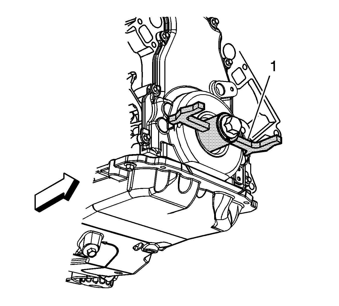
Note: Align the tapered legs of the tool with the machined alignment surfaces on the front cover.


Engine Front Cover Replacement Except 6.2L (LS9) and 7.0L
Special Tools
| • | J 41480 Front/Rear Cover Alignment - Oil Pan Surface |
| • | J 41476 Front and Rear Cover Alignment (Crankshaft Oil Seal Area) |
Removal Procedure
- Remove the crankshaft balancer. Refer to Crankshaft Balancer Replacement.
- Remove the water pump. Refer to Water Pump Replacement.
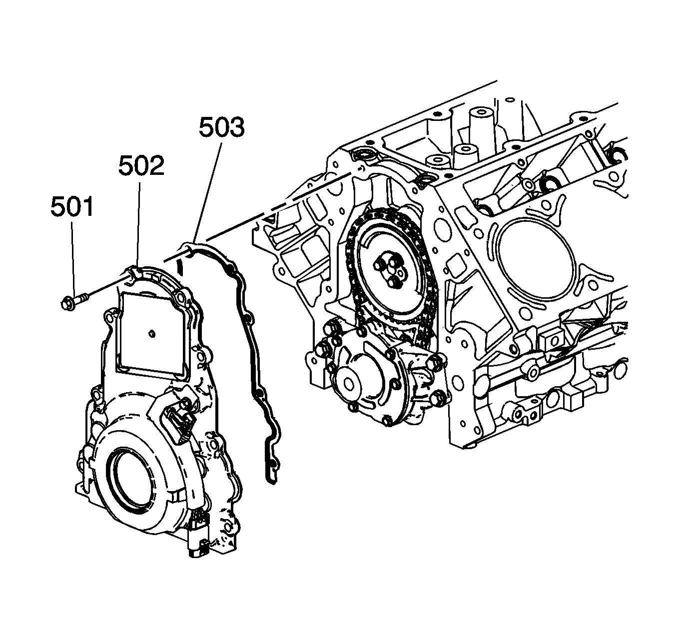
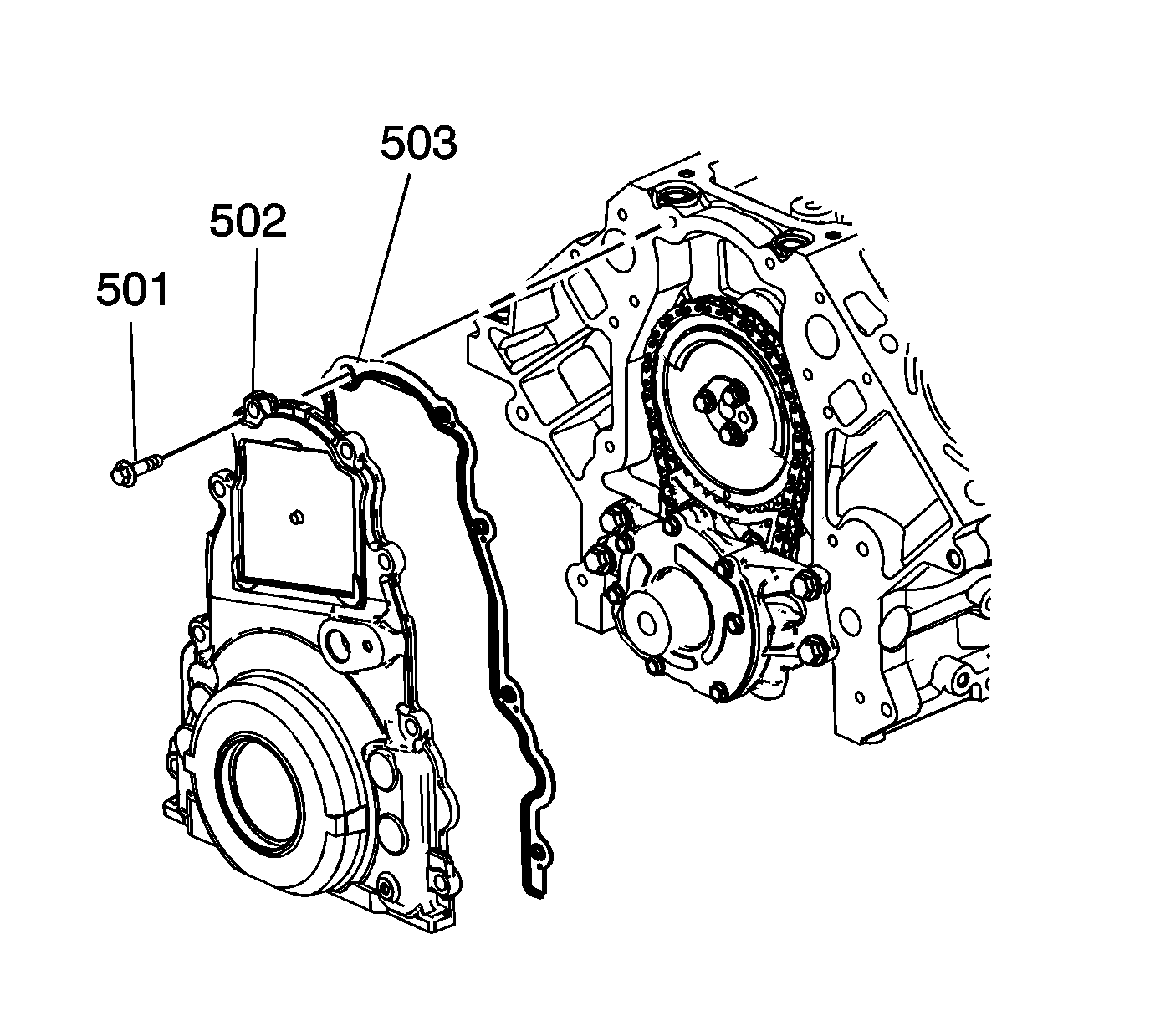
- Remove the front cover bolts (501).
- Remove the front cover (502) and gasket (503).
- Discard the front cover gasket.
- Clean and inspect the engine front cover. Refer to Engine Front Cover Cleaning and Inspection.
- Remove the oil seal (140).
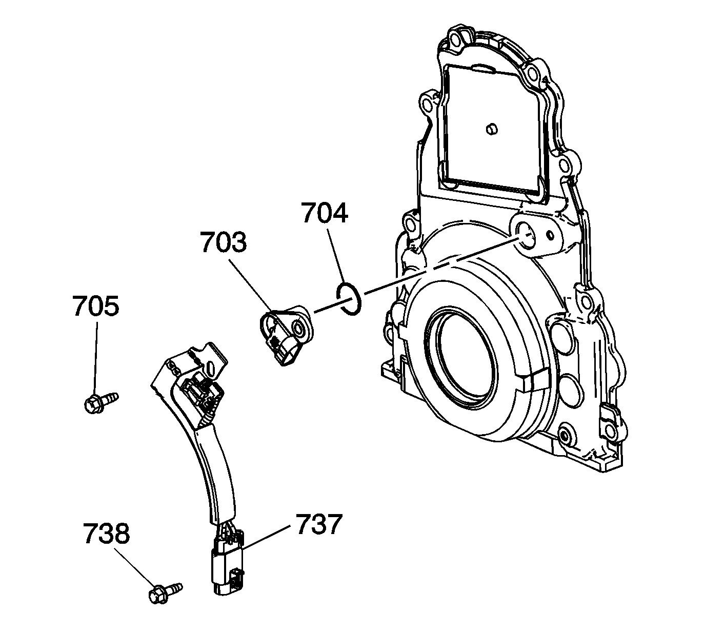
- Remove the bolts (705, 738), camshaft position sensor (703), and wire harness (737).
- Remove the O-ring (704) from the sensor as required.
Installation Procedure
- Apply a 5 mm (0.2 in) bead of sealant 20 mm (0.8 in) long to the engine block. Refer to Adhesives, Fluids, Lubricants, and Sealers for the correct part number.
- Install the front cover gasket (503), front cover (502), and bolts (501).
- Tighten the cover bolts finger tight. Do not overtighten.
- Install the J 41480 .
- Install the J 41476 .
- Install the crankshaft balancer bolt.
- Tighten the crankshaft balancer bolt by hand until snug. Do not overtighten.
- Tighten the J 41480 .
- Tighten the engine front cover bolts to 25 N·m (18 lb ft).
- Remove the tools.
- Measure the oil pan surface flatness, front cover-to-engine block.
- If the front cover-to-engine block oil pan surface alignment is not within specifications, repeat the cover alignment procedure.
- If the correct front cover-to-engine block alignment cannot be obtained, replace the front cover.
- Inspect the camshaft position sensor O-ring seal (704) for cuts or damage. If the seal is not cut or damaged, it may be used again.
- Lubricate the O-ring seal with clean engine oil.
- Install the O-ring seal onto the sensor (703).
- Install the sensor to the cover.
- Install the camshaft position sensor wire harness (737) and bolts (705, 738).
- Install the water pump. Refer to Water Pump Replacement.
- Install the crankshaft balancer. Refer to Crankshaft Balancer Replacement.
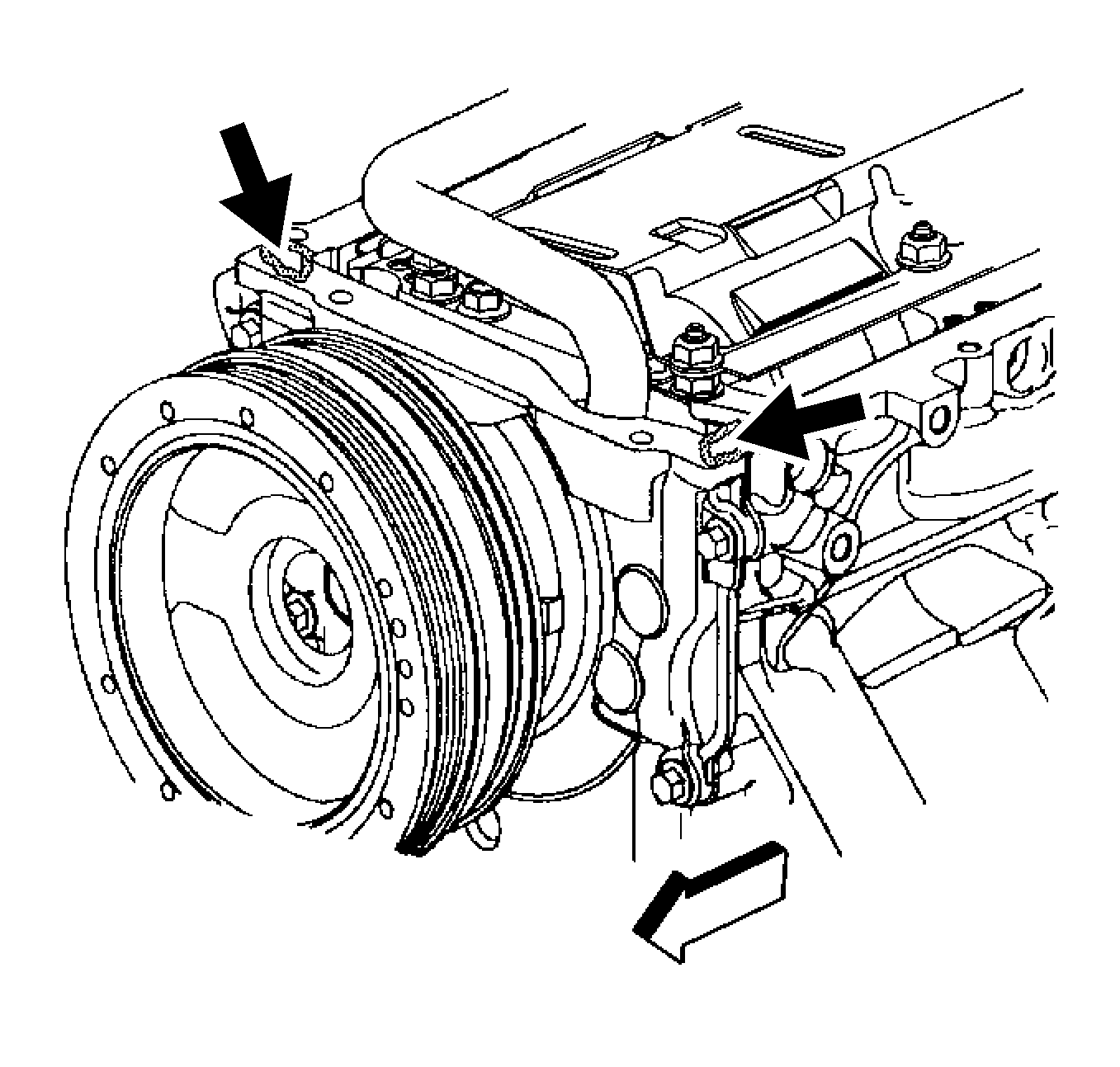
Apply the sealant directly onto the tabs of the front cover gasket that protrude into the oil pan surface.
Note:
• Do not use the crankshaft oil seal or the engine front cover gasket again. • Do not apply any type of sealant to the front cover gasket, unless specified. • The special tools in this procedure are used to properly align the engine front cover at the oil pan surface and to center the crankshaft front oil seal. - All gasket surfaces should be free of oil or other foreign material during assembly. - The crankshaft front oil seal MUST be centered in relation to the crankshaft. - The oil pan sealing surface at the front cover and engine block MUST be aligned within specifications. - An improperly aligned front cover may cause premature front oil seal wear and/or engine assembly oil leaks.
Caution: Refer to Fastener Caution in the Preface section.
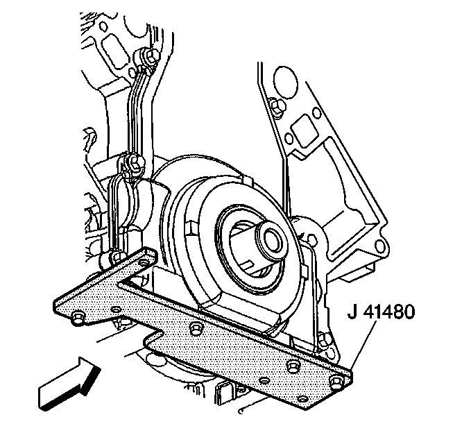
Note: Start the tool-to-front cover bolts. Do not tighten the bolts at this time.
Tighten
Tighten the tool-to-engine block bolts to 25 N·m (18 lb ft).
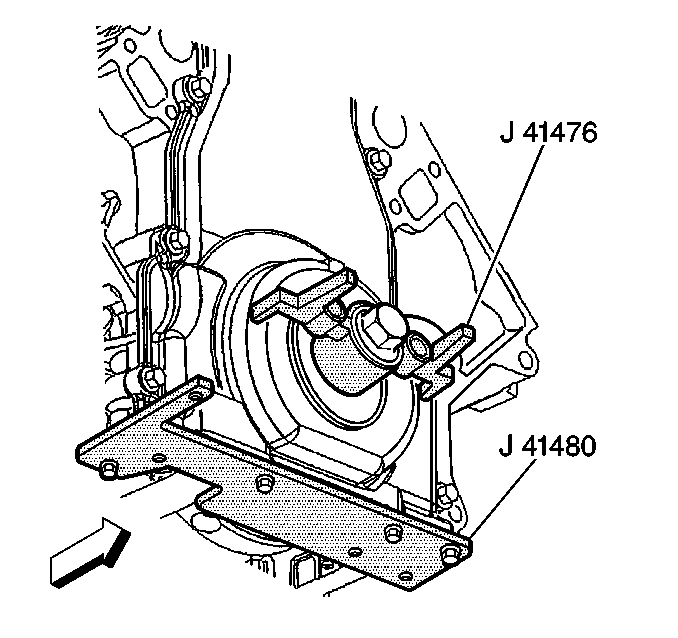
Note: Align the tapered legs of the tool with the machined alignment surfaces on the front cover.
Tighten
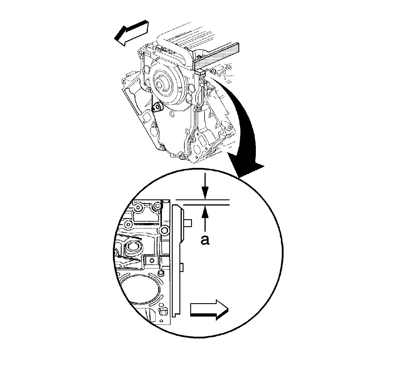
| 8.1. | Place a straight edge across the engine block and front cover oil pan sealing surfaces. |
Avoid contact with the portion of the gasket that protrudes into the oil pan surface.
| 8.2. | Insert a feeler gage between the front cover and the straight edge tool. The cover must be flush with the oil pan surface, or no greater than 0.5 mm (0.02 in) (a) below flush. |
Tighten
Tighten the bolts to 12 N·m (106 lb in).
