Evaporative Emission Hoses/Pipes Replacement - Engine Chassis
Removal Procedure
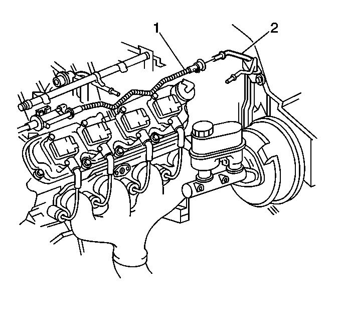
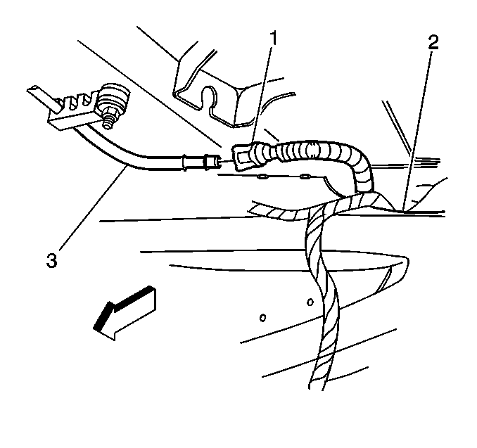
- Disconnect the engine purge pipe (1) from the chassis purge pipe (2).
- Cap the engine purge pipe in order to prevent possible contamination.
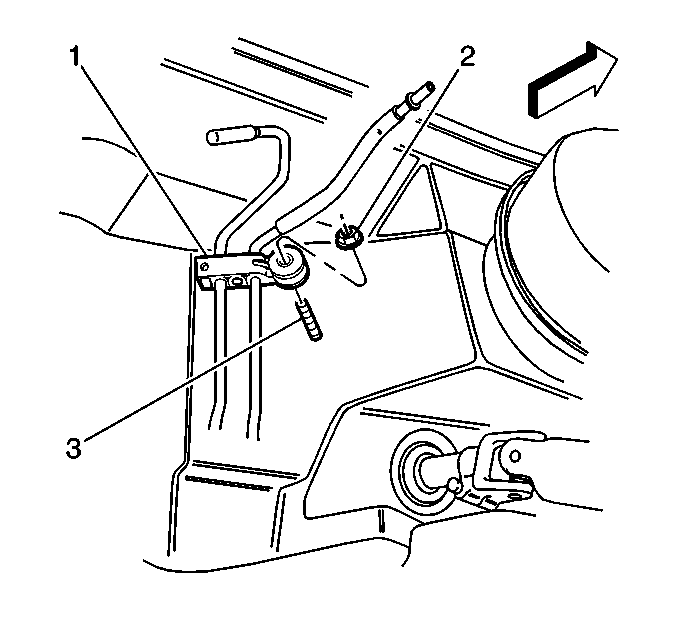
- Disconnect the chassis fuel and evaporative emission (EVAP) pipe retainer (1) from the upper front of dash mounting stud (3).
- Raise the vehicle. Refer to Lifting and Jacking the Vehicle.
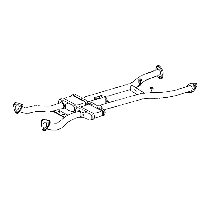
- Remove the exhaust intermediate pipe. Refer to Intermediate Pipe Replacement.
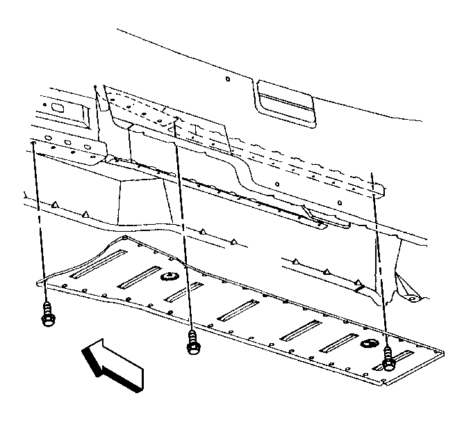
- Remove the floor panel tunnel reinforcement. Refer to Floor Panel Tunnel Panel Reinforcement Replacement.
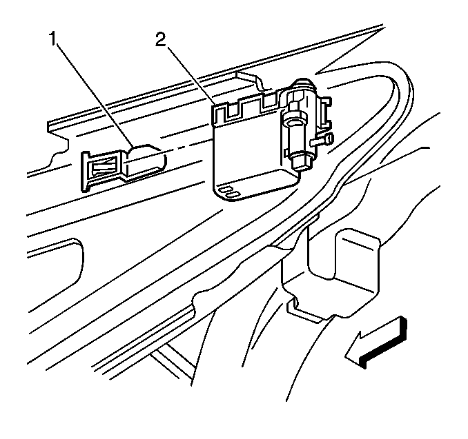
- Remove the EVAP canister vent valve (2) from the bracket (1).
- Disconnect the rear purge pipe (1) at the chassis purge pipe (3).
- Cap the rear purge pipe.
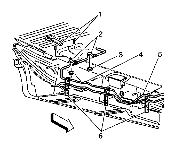
- Remove the chassis purge pipe (4) rear underbody retainer nuts (3).
- Remove the chassis purge pipe (4) from the rear underbody retainers (2).
- Disconnect the chassis purge pipe (4) from the side underbody retainers (6).
- Remove the chassis purge pipe.
Installation Procedure
- Install the chassis purge pipe (4) into the side underbody retainers (6).
- Install the chassis purge pipe (4) into the rear underbody retainers (2).
- Install the underbody retainers (2) on the mounting studs (1).
- Install the chassis purge pipe (4) underbody retainer nuts (3).
- Uncap the rear EVAP pipe.
- Connect the rear EVAP pipe (1) to the chassis purge pipe (3).
- Install the EVAP canister vent valve (2) to the bracket (1).
- Install the floor panel tunnel reinforcement. Refer to Floor Panel Tunnel Panel Reinforcement Replacement.
- Install the exhaust intermediate pipe.
- Lower the vehicle.
- Uncap the engine purge pipe.
- Connect the chassis fuel and EVAP pipe retainer (1) at the upper front of dash mounting stud (3).
- Connect the engine purge pipe (1) to the chassis purge pipe (2).
Warning: Refer to Fuel and Evaporative Emission Pipe Warning in the Preface section.

Note:
• Follow the same routing as the original pipe. • Secure the pipe in order to prevent chafing. • Do not kink or bend the pipe.
Caution: Refer to Fastener Caution in the Preface section.
Tighten
Tighten the EVAP pipe retainer bracket nuts to 6 N·m (53 lb in).


Tighten
Tighten the fuel and EVAP pipe bracket retainer nut to 6 N·m (53 lb in).

Evaporative Emission Hoses/Pipes Replacement - Engine Chassis/Tank
Removal Procedure
- Raise the vehicle. Refer to Lifting and Jacking the Vehicle.
- For vehicles equipped with an automatic transmission, remove the right muffler. Refer to Exhaust Muffler Replacement - Right Side.
- Remove the evaporative emission (EVAP) vent valve (2) from the bracket (1).
- Disconnect the rear EVAP purge pipe (1) at the chassis EVAP purge pipe (3).
- Cap the chassis EVAP purge pipe.
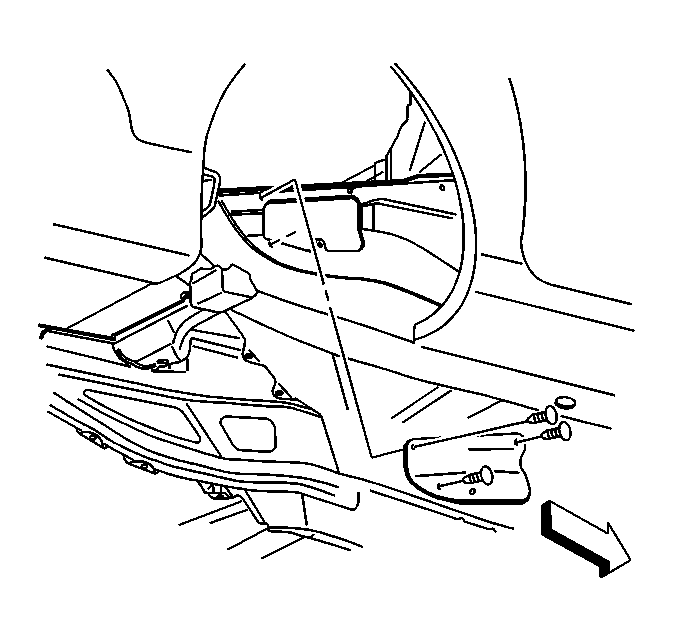
- Remove the right rear wheelhouse panel. Refer to Rear Wheelhouse Panel Liner Replacement.
- Remove the EVAP canister access cover.
- Disconnect the EVAP purge pipe at the canister.
- Remove the rear EVAP purge pipe.


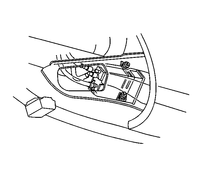
Installation Procedure
- Route the EVAP purge pipe through the right tunnel brace opening.
- Connect the EVAP purge pipe to the canister.
- Remove the cap from the chassis EVAP purge pipe.
- Connect the rear EVAP purge pipe (1) to the chassis EVAP purge pipe (3).
- Install the EVAP vent valve (2) to the bracket (1).
- For vehicles equipped with automatic transmission, install the right muffler. Refer to Exhaust Muffler Replacement - Right Side.
- Install the EVAP canister access cover.
- Install the right rear wheelhouse panel. Refer to Rear Wheelhouse Panel Liner Replacement.
- Lower the vehicle.
Warning: Refer to Fuel and Evaporative Emission Pipe Warning in the Preface section.


Evaporative Emission Hoses/Pipes Replacement - Engine Tank/Tank
Removal Procedure
- Disconnect the negative battery cable. Refer to Battery Negative Cable Disconnection and Connection.
- Relieve the fuel system pressure. Refer to the Fuel Pressure Relief.
- Drain the fuel tanks below the level of the fuel tank crossover hose. Refer to Fuel Tank Draining.
- For vehicles equipped with automatic transmission, remove the left and right muffler. Refer to Exhaust Muffler Replacement - Right Side , and to Exhaust Muffler Replacement - Left Side.
- Disconnect the tank crossover hose (5) at the right fuel tank and the left fuel tank.
- Disconnect the evaporative emission (EVAP) pipe (2) at the right tank EVAP pipe (3) and the left tank EVAP pipe (1).
- Remove the rear EVAP pipe (2).
- Cap the open pipes in order to prevent possible contamination.
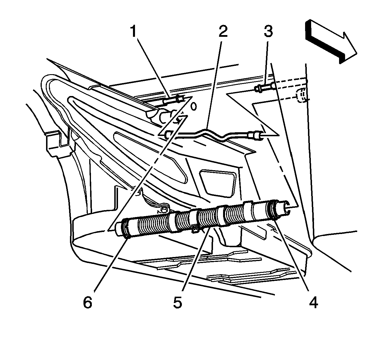
Installation Procedure
- Remove the caps from the pipes.
- Connect the EVAP pipe (2) at the right tank EVAP pipe (3) and the left tank EVAP pipe (1).
- Connect the tank crossover hose (5) at the right fuel tank and the left fuel tank.
- Push the clamp (4) outboard against the fuel tank, keeping the clamp parallel with the white stripe on the tank crossover hose.
- Install the right and left muffler. Refer to Exhaust Muffler Replacement - Right Side and to Exhaust Muffler Replacement - Left Side.
- Refill the fuel system.
- Tighten the fuel filler cap.
- Connect the negative battery cable. Refer to Battery Negative Cable Disconnection and Connection.
- Use the following procedure in order to inspect for leaks:
- Program the transmitters. Refer to Transmitter Programming.

Caution: Replace the EVAP pipes and hoses with the original equipment or parts that meet the GM specifications for those parts. The replacement EVAP pipe must have the same type of fittings as the original pipe in order to ensure the integrity of the connection. When replacing EVAP hoses, use only reinforced fuel-resistant hose identified with the word Fluoroelastomer or GM 6163-M on the hose. The inside hose diameter must match the outside pipe diameter. Do not use rubber hose within 100 mm (4 in) of any part of the exhaust system or within 254 mm (10 in) of the catalytic converter.
Caution: Refer to Fastener Caution in the Preface section.
Tighten
Tighten the tank crossover hose clamps to 4 N·m (35 lb in).
| 9.1. | Turn the ignition switch ON, with the engine OFF for 2 seconds. |
| 9.2. | Turn the ignition switch OFF, for 10 seconds. |
| 9.3. | Turn the ignition switch ON, with the engine OFF. |
| 9.4. | Inspect for fuel leaks. |
Evaporative Emission Hoses/Pipes Replacement - Engine Vent
Removal Procedure
- Raise the vehicle. Refer to Lifting and Jacking the Vehicle.
- For vehicles equipped with automatic transmission, remove the right muffler. Refer to Exhaust Muffler Replacement - Right Side.
- Disconnect the vent hose (2) from the evaporative emission (EVAP) vent valve (1).
- Remove the clamp from the vent hose.
- Remove the right rear wheelhouse panel. Refer to Rear Wheelhouse Panel Liner Replacement.
- Remove the EVAP canister access cover.
- Disconnect the vent hose from the EVAP canister.
- Remove the vent hose.
- Cap the EVAP vent valve and the EVAP canister in order to prevent possible EVAP system contamination.
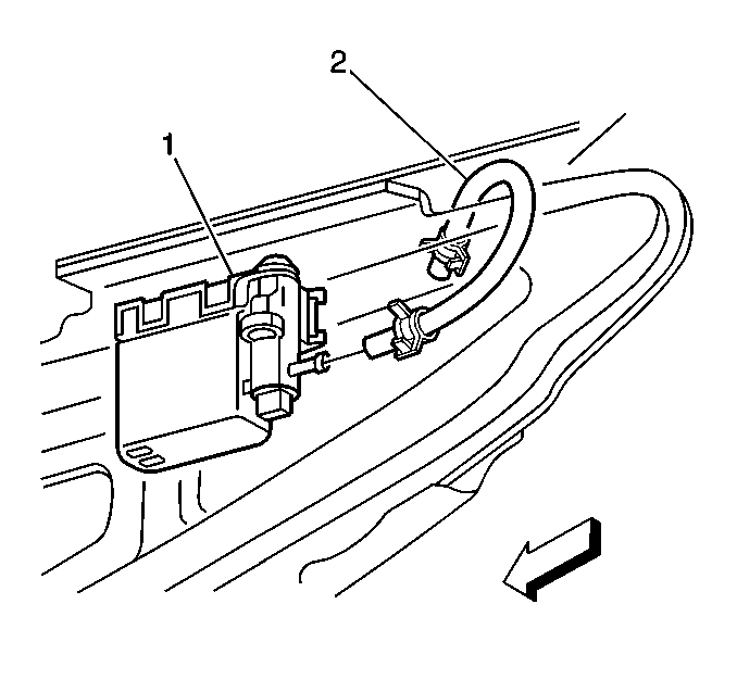

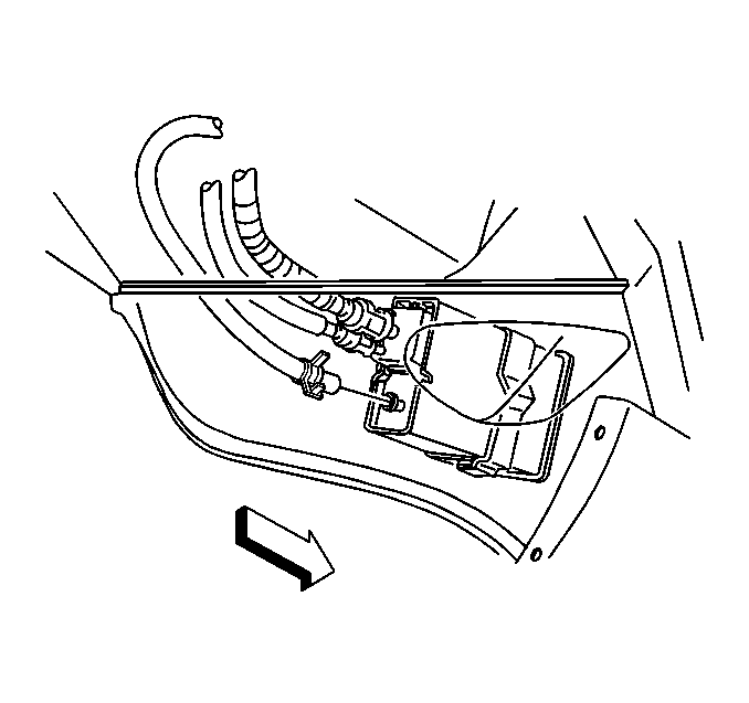
Installation Procedure
- Remove the caps from the EVAP vent valve and the EVAP canister.
- Route the vent hose over the floor panel tunnel panel rear brace.
- Install the clamps on the vent hose.
- Connect the vent hose to the EVAP canister.
- Connect the vent hose (2) to the EVAP vent valve.
- For vehicles equipped with automatic transmission, install the right muffler. Refer to Exhaust Muffler Replacement - Right Side.
- Install the EVAP canister access cover.
- Install the right rear wheelhouse panel. Refer to Rear Wheelhouse Panel Liner Replacement.
- Lower the vehicle.

Caution: Replace the EVAP pipes and hoses with the original equipment or parts that meet the GM specifications for those parts. The replacement EVAP pipe must have the same type of fittings as the original pipe in order to ensure the integrity of the connection. When replacing EVAP hoses, use only reinforced fuel-resistant hose identified with the word Fluoroelastomer or GM 6163-M on the hose. The inside hose diameter must match the outside pipe diameter. Do not use rubber hose within 100 mm (4 in) of any part of the exhaust system or within 254 mm (10 in) of the catalytic converter.


