For 1990-2009 cars only
Removal Procedure
- Raise and support the vehicle. Refer to Lifting and Jacking the Vehicle.
- Remove the tire and wheel assembly. Refer to Tire and Wheel Removal and Installation.
- Remove the front transverse spring. Refer to Front Transverse Spring Replacement.
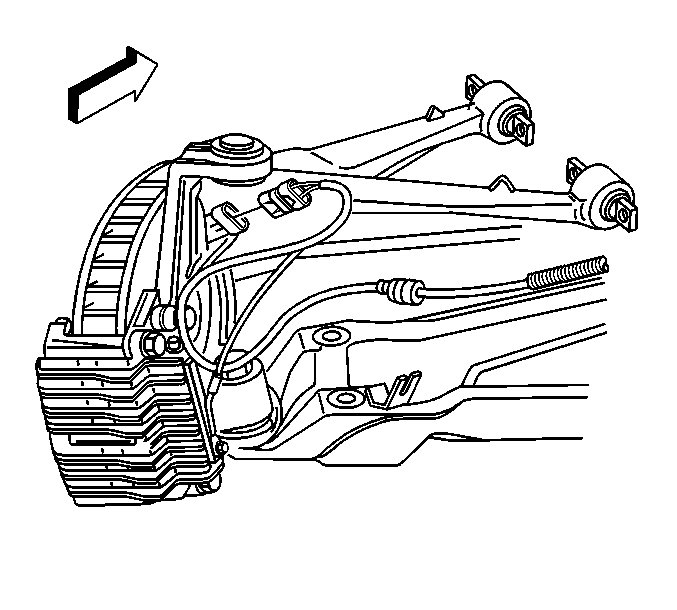
- Disconnect the electrical connector from the wheel speed sensor.
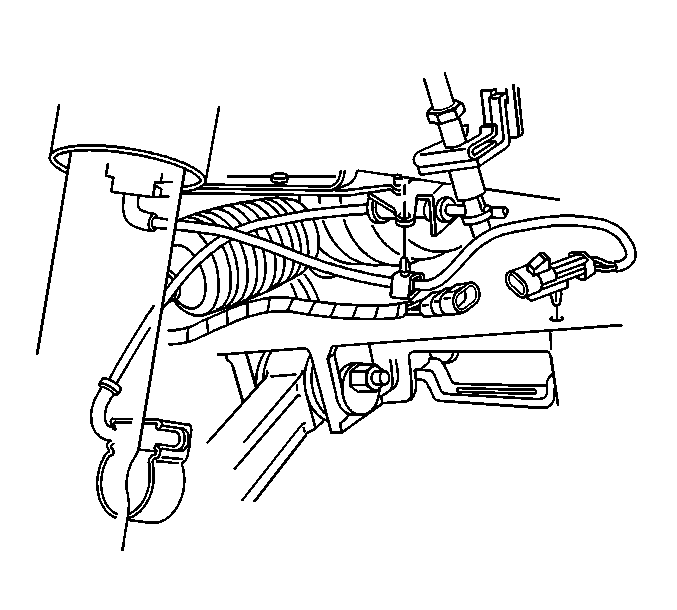
- Disconnect the electronic suspension control (ESC) electrical connector from the shock, if equipped.
- Remove the shock absorber from the lower control arm. Refer to Shock Absorber Replacement
- Remove the stabilizer shaft link from the lower control arm. Refer to Stabilizer Shaft Link Replacement
- Remove the lower ball joint from the steering knuckle. Refer to Steering Linkage Outer Tie Rod Replacement
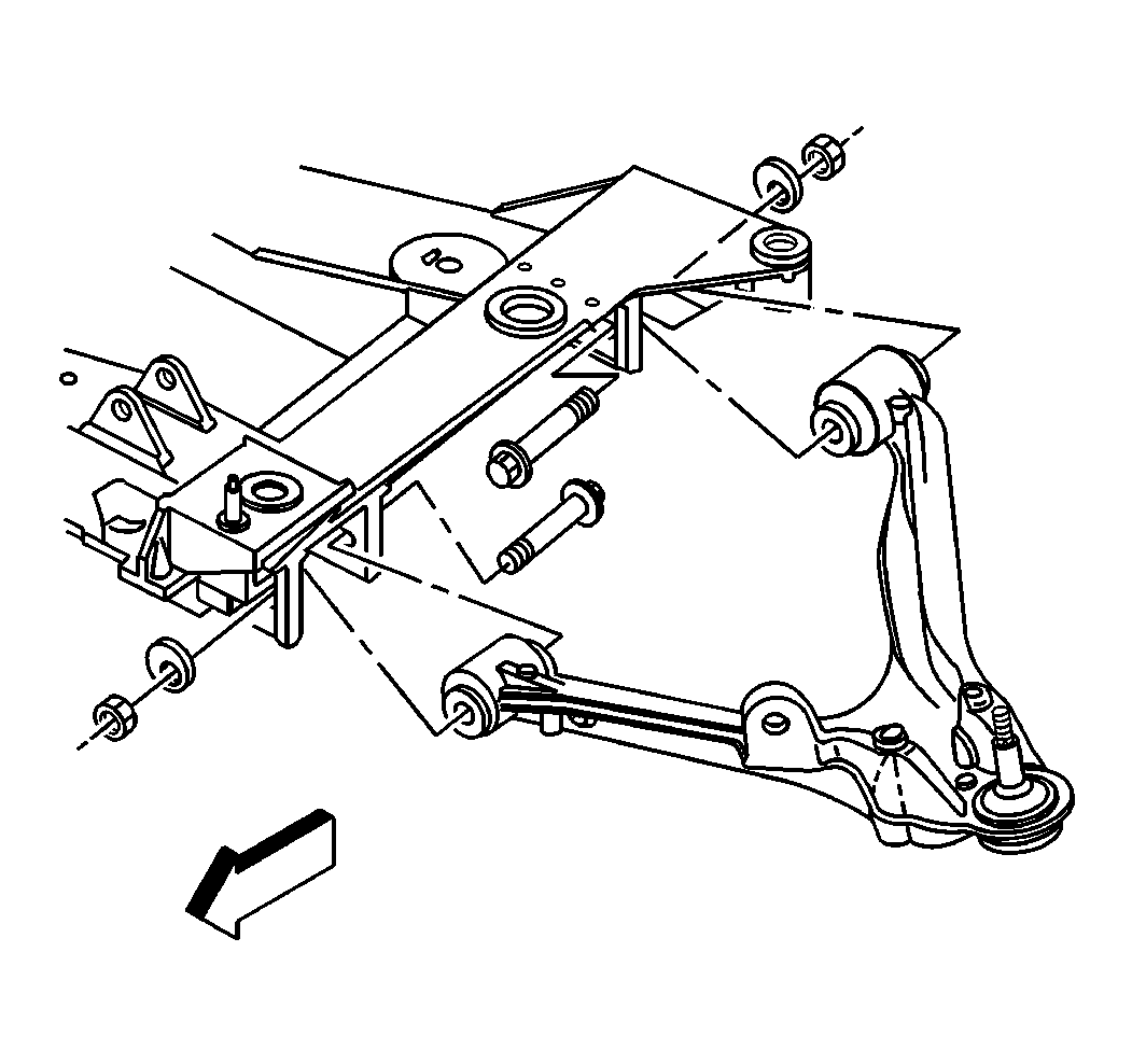
- Mark the position of the cam bolts for orientation when installing.
- Remove the cam bolts, washers, and nuts retaining the control arm to the crossmember. ZR1 and Z06, discard the cam bolts.
- Remove the lower control arm from the vehicle.


Note: For the vehicles with the ZR1 and the ZO6 options, anytime the lower control arms removed, the lower control arm to crossmember cam bolts must be replaced.
Installation Procedure
- Install the lower control arm in the vehicle.
- Install the cam bolts, washers, and nuts retaining control arm to the crossmember. ZR1 and Z06, use NEW cam bolts.
- Support the lower control arm with a jackstand.
- Install the lower ball joint in the steering knuckle. Refer to Steering Linkage Outer Tie Rod Replacement.
- Install the stabilizer shaft link to the lower control arm. Refer to Stabilizer Shaft Link Replacement.
- Install the front transverse spring Refer to Front Transverse Spring Replacement.
- Install the shock absorber to the lower control arm. Refer to Shock Absorber Replacement.
- Connect the ESC electrical connector to the shock, if equipped.
- Connect the electrical connector to the wheel speed sensor.
- Remove the jackstands.
- Install the tire and wheel assembly. Refer to Tire and Wheel Removal and Installation.
- Lower the vehicle.
- Perform a front wheel alignment. Refer to Wheel Alignment Measurement.

Note: DO NOT tighten the cam bolts to specifications until after the alignment has been performed.


